- Preface
- Overview of Chassis Installation Steps
- Cisco CRS Carrier Routing System 8-Slot Line Card Chassis Enhanced Router Overview
- Installing Power Components
- Installing Air Circulation Components
- Installing Exterior Components
- Installing Line Cards, PLIMs, and Associated Components
- Removing Chassis Components
- Technical Specifications
- Product IDs
Cisco CRS Carrier Routing System 8-Slot Line Card Chassis Enhanced Router Installation Guide
Bias-Free Language
The documentation set for this product strives to use bias-free language. For the purposes of this documentation set, bias-free is defined as language that does not imply discrimination based on age, disability, gender, racial identity, ethnic identity, sexual orientation, socioeconomic status, and intersectionality. Exceptions may be present in the documentation due to language that is hardcoded in the user interfaces of the product software, language used based on RFP documentation, or language that is used by a referenced third-party product. Learn more about how Cisco is using Inclusive Language.
- Updated:
- October 27, 2016
Chapter: Installing Exterior Components
Installing Exterior
Components
Installing Exterior Components
This chapter provides instructions for installing the exterior cosmetic components on the Cisco CRS 8-Slot Line Card Chassis Enhanced router. This chapter presents the following topics:
Overview of the Exterior Components
Exterior cosmetic components for the Cisco CRS 8-Slot Line Card Chassis Enhanced router are not required to be installed; they are provided as optional components (except for the cable management bracket, which is preinstalled). The Cisco CRS 8-Slot Line Card Chassis Enhanced router is shipped with the following exterior components:
- Inlet grille (shipped separately)
- Front cover (shipped separately)
You can also install the optional exterior exhaust grille for the rear of the chassis. This exterior component for the rear of the chassis does not ship automatically with the product; it must be ordered separately. For more information about installing the rear exhaust grille, see Installing a Rear Exhaust Grille, page 4-5 .
Installing the Front Side Exterior Components
This section contains the following procedures:
Installing the Inlet Grille
This section describes how to install the inlet grille on a Cisco CRS 8-Slot Line Card Chassis Enhanced router. The grille covers the power module and air intake areas at the bottom of the front (PLIM) side of the chassis, just below the card cage.
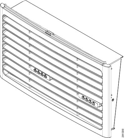
Prerequisites
Before installing the inlet grille, you should mount the chassis in a rack and remove the rear handle pulls. See the Cisco CRS Carrier Routing System 8-Slot Line Card Chassis Enhanced Router Unpacking, Moving, and Securing Guide.
Required Tools and Equipment
- ESD-preventive wrist strap
- Inlet grille (Cisco product number: CRS-8-PW-GRILL)
Steps
To install the inlet grille, perform the following steps:
| Step 1 | Remove the new inlet grille from its packaging, then set the packaging aside. |
| Step 2 | Attach the ESD-preventive wrist strap to your wrist and connect its leash to one of the ESD connection sockets on the front (PLIM) side of the chassis or a bare metal surface on the chassis. |
| Step 3 | Align and insert the hooks at the bottom of the inlet grille into the cutouts at the bottom of the chassis casing on the front (PLIM) side of the chassis, just in front of the power modules. |
| Step 4 | Rotate the top of the inlet grille toward the chassis, and snap it into place on the ball studs. |
What to Do Next
After performing this task, you may install the front cover. See Installing the Front Cover.
Installing the Front Cover
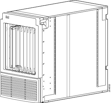
This section describes how to install the front cover. The front cover protects the card cage on the front (PLIM) side of the chassis.
The following figure shows the front cover installed on the Cisco CRS 8-Slot Line Card Chassis Enhanced router.
Prerequisites
Before installing the front cover, you should mount the chassis in a rack and remove the rear handle pulls. See the Cisco CRS Carrier Routing System 8-Slot Line Card Chassis Enhanced Router Unpacking, Moving, and Securing Guide .
Required Tools and Equipment
- ESD-preventive wrist strap
- Number 1 Phillips screwdriver
- Front cover (Cisco product number: CRS-8-FRONT-COVER=) [Optional]
Steps
To install the front cover, perform the following steps:
| Step 1 | Remove the new front cover from its packaging. | ||
| Step 2 | Attach the ESD-preventive wrist strap to your wrist and connect its leash to one of the ESD connection sockets on the front (PLIM) side of the chassis or a bare metal surface on the chassis. | ||
| Step 3 | Install the
ball stud retainer brackets on the vertical chassis rack rails, two on the left
and two on the right.
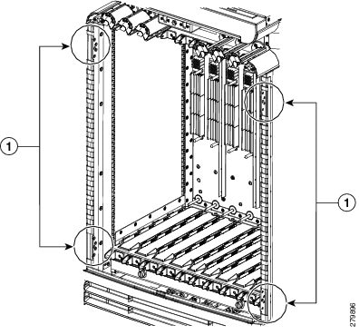
| ||
| Step 4 | Using the
screwdriver, tighten the four flat head screws that attach each ball stud
retainer bracket to the vertical chassis rack rails.
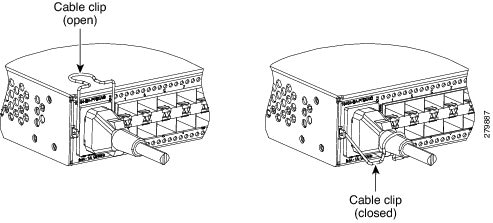 | ||
| Step 5 | Align the four ball studs on the front cover with the holes on the ball stud retainer brackets. | ||
| Step 6 | Firmly press until the four ball studs snap into place. Refer to #con_1073314/fig_1075924. |
 Feedback