- Preface
- Overview of Chassis Installation Steps
- Cisco CRS Carrier Routing System 8-Slot Line Card Chassis Enhanced Router Overview
- Installing Power Components
- Installing Air Circulation Components
- Installing Exterior Components
- Installing Line Cards, PLIMs, and Associated Components
- Removing Chassis Components
- Technical Specifications
- Product IDs
Cisco CRS Carrier
Routing System 8-Slot Line Card Chassis Enhanced Router Overview
Chassis Overview
This chapter provides an overview of the Cisco CRS 8-Slot Line Card Chassis Enhanced router. It contains the following sections:
Overview
The Cisco CRS 8-Slot Line Card Chassis Enhanced router can be installed in locations where the 16-slot system may not fit (for example, colocation facilities, data centers, and many Tier II and Tier III locations). The routing system consists of a single rack-mount chassis that contains the following major system components:
- Modular services cards (MSCs), forwarding processor (FP) cards, and label switch processor (LSP) cards, also called line cards (up to eight)
- Physical layer interface modules, or PLIMs (up to eight, one for each line card)
- Two route processor (RP) cards or two performance route processor (PRP) cards
- Switch fabric cards (four required)
- SPA Interface
Processors (SIPs) and Shared Port Adapters (SPAs) which can be installed
instead of PLIMs
- SIP is a carrier card that is similar to a PLIM and inserts into a line card chassis slot and interconnects to an MSC, FP, or LSP like a PLIM. Unlike PLIMs, SIPs provide no network connectivity on their own.
- SPA is a modular type of port adapter that inserts into a subslot of a compatible SIP carrier card to provide network connectivity and increased interface port density. A SIP can hold one or more SPAs, depending on the SIP type and the SPA size. POS/SDH and Gigabit Ethernet SPAs are available.
- A chassis midplane that connects MSCs, FPs, or LSPs to their PLIMs and to switch fabric cards
The Cisco CRS 8-Slot Line Card Chassis Enhanced router supports 40G, 140G, and 400G fabric cards, as follows:
- The Cisco CRS-1 Carrier Routing System uses fabric cards designed for 40 G operation (CRS-8-FC/S or CRS-8-FC/M cards).
- The Cisco CRS-3 Carrier Routing System uses fabric cards designed for 140G operation (CRS-8-FC140/S or CRS-8-FC140/M cards).
- The Cisco CRS-X Carrier Routing System uses fabric cards designed for 400G operation (CRS-8-FC400/S fabric card and CRS-8-FC400/M fabric card).
For detailed information about the CRS back-to-back system, see Introduction to the CRS-3 Back-to-Back System .
A mixture of 40G, 140G, and 400G fabric cards is not supported except during migration.
 Note | Throughout this document, the generic term Cisco CRS Carrier Routing system refers to the Cisco CRS-1, Cisco CRS-3, and Cisco CRS-X Carrier Routing Systems, unless otherwise specified. |
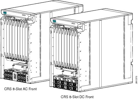
The following figure shows the front view of a Cisco CRS 8-Slot Line Card Chassis Enhanced router with AC and DC power shelves installed.
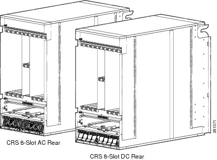
The following figure shows the rear view of a Cisco CRS 8-Slot Line Card Chassis Enhanced router with AC and DC power systems installed.
Chassis Components
This section lists the main components of a Cisco CRS 8-Slot Line Card Chassis Enhanced router. It primarily identifies the components that are considered field-replaceable units (FRUs), but where additional detail is useful identifies subassemblies that are not field replaceable. The Cisco CRS 8-Slot Line Card Chassis Enhanced router contains:
- As many as eight MSC, FP or LSP cards (all referred to as line cards), and eight PLIMs. The line card and PLIM are an associated pair of cards that connect through the chassis midplane. The line card provides the forwarding engine for Layer 3 routing of user data that is switched through the system, and the PLIM provides the physical interface and connectors for the user data. The line card can be associated with several different PLIMs, which provide different interface speeds and technologies.
Note | For a complete list of line cards, route processors, SPAs and SIPs, and interface modules supported in the Cisco CRS 8-Slot Line Card Chassis Enhanced router, go to the Cisco Carrier Routing System Data Sheets at: http://www.cisco.com/en/US/products/ps5763/products_data_sheets_list.html . |
- Chassis midplane. The midplane connects a line card to its associated PLIM. The midplane design allows a line card to be removed from the chassis without having to disconnect the cables that are attached to the associated PLIM. The midplane distributes power, connects the line cards to the switch fabric cards, and provides control plane interconnections. The midplane is not field replaceable by the customer.
Note | For a complete list of available PLIMs, consult your Cisco sales representative or visit: http://www.cisco.com |
- One or two route processor cards (RPs). The RPs provide the intelligence of the system by functioning as the Cisco CRS 8-Slot Line Card Chassis Enhanced router system controller (serving as part of the control plane in multi-chassis systems) and providing route processing. Only one RP is required for system operation. For redundant operation, you can order a second RP as an option (CRS-8-RP/R). When two RPs are used, only one RP is active at a time. The second RP acts as a “standby” RP, serving as a backup if the active RP fails.
The RP also monitors system alarms and controls the system fans. LEDS on the front panel indicate active alarm conditions.
A Performance Route Processor (PRP) is also available for the Cisco CRS 8-Slot Line Card Chassis Enhanced router. Two PRPs perform the same functions as two RPs, but provide enhanced performance for both route processing and system controller functionality.
Note | A chassis may not be populated with a mix of RP and PRP cards. Both route processor cards should be of the same type (RP or PRP). If you are using the Cisco CRS-X system, PRPs are required. |
- Four half-height switch fabric cards (SFCs). These fabric cards provide the three-stage Benes switch fabric for the routing system.
Note | The Cisco CRS 8-Slot Line Card Chassis Enhanced router supports either 40G fabric (FC/S cards), 140G fabric (FC-140/S cards), or 400G fabric (FC-400/S cards). A router with a mix of 40G, 140G, and 400G fabric cards is not a supported mode of operation. Such a mode is temporarily allowed only during the upgrade process. |
- A power system that provides redundant power to the chassis. Two types of power systems are available: either AC or DC power.
- Upper and lower fan trays. The fans pull cool air through the chassis. A removable air filter is located below the PLIM card cage at the front of the chassis.
Chassis Overview
This section provides an overview of the physical chassis characteristics:
Slot Numbers
The following figure shows the slot numbering on the front (PLIM) side of the Cisco CRS 8-Slot Line Card Chassis Enhanced router.
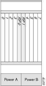
As shown, the components on the front (PLIM) side of the chassis include:
- Eight PLIM slots: left to right, 0, 1, 2, 3, 4, 5, 6, 7
- Two route processor card slots, RP0 and RP1
- Two power supplies (A and B) - 6 power modules (PMs) for AC & 8 power modules (PMs) for DC
The following image shows the slot numbers on the rear (MSC) side of the Cisco CRS 8-Slot Line Card Chassis Enhanced router.
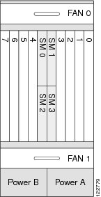
As shown, the components on the rear (MSC) side of the chassis include:
- Upper fan tray 0
- Card cage,
including:
- Eight line card slots (0, 1, 2, 3, 4, 5, 6, 7)
- Four half-height switch fabric card slots (SM0, SM1, SM2, and SM3)
- Lower fan tray 1
- Two power supplies (A and B) - 6 power modules (PMs) for AC & 8 power modules (PMs) for DC
The MSC slot numbers on the rear of the chassis are reversed from the PLIM slot numbers on the front side of the chassis. A mated MSC and PLIM are slot specific and mated through the midplane. The MSC slot 0, on the far right side of the chassis looking at it from the rear (MSC) side, is mated with the PLIM slot 0, on the far left side of the chassis looking at it from the front (PLIM) side. All other MSC and PLIM slots (1 through 7) are mated via matching slot numbers through the midplane also.
Cable Management
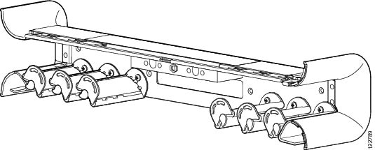
The Cisco CRS 8-Slot Line Card Chassis Enhanced router has cable management features for the front (PLIM) side of the chassis, just above the card cage. The horizontal cable management trays have a special telescoping feature that allows them to be extended when the chassis is upgraded with higher-density cards. This extension also helps when installing the cables in the chassis.
Note | Do not install the front cover on the chassis when the telescoping feature is in use. |
The following figure shows the cable management bracket.
Safety Guidelines
Before you perform any procedure in this document, review the safety guidelines in this section to avoid injuring yourself or damaging the equipment.
Note | Although power shelves may be installed or removed without powering down the system, for safety purposes we recommend that you power down the system before you install or remove a power shelf. |
The following guidelines are for your safety and to protect equipment. The guidelines do not include all hazards. Be alert.
Note | Review the safety warnings listed in Regulatory Compliance and Safety Information that are applicable to your router before installing, configuring, or troubleshooting any installed card. |
- Never attempt to lift an object that might be too heavy for you to lift by yourself.
- Keep the work area clear and dust free during and after installation. Do not allow dirt or debris to enter into any laser-based components.
- Keep tools and router components away from walk areas.
- Do not wear loose clothing, jewelry, and other items that could get caught in the router while working with line cards, or their associated components.
- Use Cisco equipment in accordance with its specifications and product-usage instructions.
- Do not work alone if potentially hazardous conditions exist.
- Make sure your installation follows national and local electrical codes: in the United States, National Fire Protection Association (NFPA) 70, United States National Electrical Code; in Canada, Canadian Electrical Code, part I, CSA C22.1; in other countries, International Electrotechnical Commission (IEC) 60364, part 1 through part 7.
- Connect only a DC power source that follows the safety extra-low voltage (SELV) requirements in UL/CSA/IEC/EN 60950-1 and AS/NZS 60590 to the DC-input power system.
- Make sure that you have a readily accessible two-poled disconnect device incorporated in the wiring of a CRS configured with the DC-input power system.
- Make sure that you provide short-circuit (overcurrent) protection as part of the building installation.
Preventing Electrostatic Discharge
Electrostatic discharge (ESD) damage, which can occur when electronic cards or components are improperly handled, results in complete or intermittent failures. We recommend to use an ESD-preventive strap whenever you handle network equipment or one of its components.
Following are guidelines for preventing ESD damage:
- Always use an ESD-preventive wrist or ankle strap and ensure that it makes good skin contact. Connect the equipment end of the connection cord to an ESD connection socket on the router or to a bare metal surface on the chassis.
- Handle a card by its ejector levers, when applicable, or the card’s metal carrier only; avoid touching the board or connector pins.
- Place a removed card board-side-up on an antistatic surface or in a static-shielding bag. If you plan to return the component to the factory, immediately place it in a static-shielding bag.
- Avoid contact between the card and clothing. The wrist strap protects the board only from ESD voltage on the body; ESD voltage on clothing can still cause damage.
 Feedback