- Preface
- Overview of Chassis Installation Steps
- Cisco CRS Carrier Routing System 8-Slot Line Card Chassis Enhanced Router Overview
- Installing Power Components
- Installing Air Circulation Components
- Installing Exterior Components
- Installing Line Cards, PLIMs, and Associated Components
- Removing Chassis Components
- Technical Specifications
- Product IDs
Installing Air
Circulation Components
Installing and Upgrading Air Circulation Components
This chapter provides instructions on how to install and upgrade the Cisco CRS 8-Slot Line Card Chassis Enhanced router air circulation components.
This chapter presents the following topics:
- About Line Card Chassis Airflow
- Installing Air Circulation Components
- Upgrading Fan Trays-Summary Steps
About Line Card Chassis Airflow
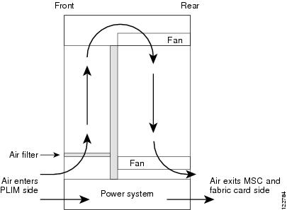
The Cisco CRS 8-Slot Line Card Chassis Enhanced router has two fan trays, each with four fans, that cool the chassis card cages.
The top fan pulls air into the lower portion of the front of the chassis, up across the cards in the front of the chassis, and through the upper fan tray. Air flows out of the upper fan tray and down across all the modular service cards and switch fabric cards through the lower fan tray; air is then exhausted out the bottom of the rear of the chassis (see Figure 1).
In addition, each AC or DC power module at the bottom of the chassis has self-contained fans that pull in cool air from the front of the chassis and exhaust the warm air out the rear of the chassis.
A replaceable air filter is located on the front of the chassis below the PLIM card cage. How often the air filters should be replaced depends on the facility environment. In a dirty environment, or when you start getting frequent temperature alarms, you should always check the intake grills for debris, and then check the air filters to see if they need to be replaced.
 Note | We recommend that you check the air filters once a month. Replace a filter when you notice a significant amount of dust. |
The Cisco CRS 8-Slot Line Card Chassis Enhanced router airflow volumes are:
Installing Air Circulation Components
This section contains the following procedures:
- Installing a Lower Fan Tray
- Installing the Chassis Air Filter
- Installing a Rear Exhaust Grille
- Installing an Upper Fan Tray
Installing a Lower Fan Tray
This section describes how to install a fan tray (if applicable) in the lower fan tray slot of the Cisco CRS 8-Slot Line Card Chassis Enhanced router. For information on the chassis airflow and circulation, see About Line Card Chassis Airflow.
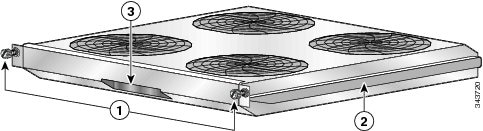
A Cisco CRS 8-Slot Line Card Chassis Enhanced router fan tray operates in either the upper or lower fan tray slot. Each fan tray installs into the rear (MSC) side of the chassis . Each fan tray contains four fans.
|
1 |
Captive screws |
3 |
Fan tray handle |
|
2 |
Fan tray rail |
|
|
Prerequisites
Before performing this task, remove the optional rear exhaust grille, if installed.
Required Tools and Equipment
You need the following tools and part to perform this task:
- ESD-preventive wrist strap
- Number 2 Phillips screwdriver
- Fan tray
Steps
To install a lower fan tray, follow these steps:
| Step 1 | Attach the ESD-preventive wrist strap to your wrist and connect its leash to one of the ESD connection sockets on the rear (MSC) side of the chassis or a bare metal surface on the chassis. | ||||
| Step 2 |
Using two hands to support the fan tray, position it in front of the fan tray bay so that the rails on the sides of the fan tray are aligned with the rail guides on the interior of the chassis.
| ||||
| Step 3 |
Slide the fan tray all the way in. Press it firmly into the chassis so that the connector on the back of the fan tray is seated firmly against the connector on the interior of the chassis.
| ||||
| Step 4 |
Using the Number 2 Phillips screwdriver, tighten the two captive screws (one for each side).
|
What to Do Next
After performing this task, reinstall the optional rear exhaust grille, if applicable.
Installing the Chassis Air Filter
This section describes how to install (if applicable) the air filter in the Cisco CRS 8-Slot Line Card Chassis Enhanced router. For further information, see About Line Card Chassis Airflow.
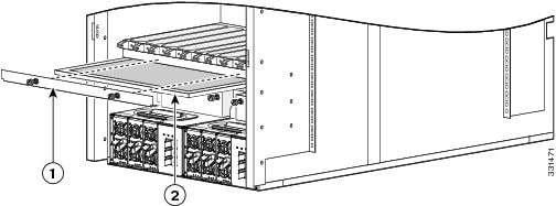
The chassis has a serviceable air filter mounted in a slide-out tray, accessible from the rear of the chassis just above the lower fan tray. The Cisco CRS 8-Slot Line Card Chassis Enhanced router air filter plugs into the front (PLIM) side of the chassis .
|
1 |
Air filter cover plate (with captive screws) |
2 |
Chassis air filter |
Prerequisites
Before performing this task, you must first remove the front cover and inlet grille, if installed.
 Caution | Never operate the Cisco CRS 8-Slot Line Card Chassis Enhanced router without an air filter. Doing so can damage the hardware. |
Required Tools and Equipment
You need the following tools and part to perform this task:
- ESD-preventive wrist strap
- Number 2 Phillips screwdriver
- Chassis air filter
Steps
To install the chassis air filter, follow these steps:
| Step 1 | Attach the ESD-preventive wrist strap to your wrist and connect its leash to one of the ESD connection sockets on the front (PLIM) side of the chassis or a bare metal surface on the chassis. |
| Step 2 | Using two hands to support the air filter, orient it so that the ridge on the front of the air filter faces outward from the front of the chassis and the wire-grid backing support is facing up. |
| Step 3 | Slide the air filter into the air filter slot until it is seated fully within the slot. |
| Step 4 | Hold the air filter cover plate in place and using a Number 2 Phillips screwdriver, tighten the two captive screws on the front of the plate. |
What to Do Next
After performing this task, reinstall the inlet grill and the front cover, if applicable.
Installing a Rear Exhaust Grille
This section describes how to install a rear exhaust grille on the Cisco CRS 8-Slot Line Card Chassis Enhanced router.
Prerequisites
There are no prerequisites for this task.
Required Tools and Equipment
You need the following tools and part to perform this task:
- ESD-preventive wrist strap
- Number 2 Phillips screwdriver
- Rear exhaust grille
Steps
To install a rear exhaust grille, follow these steps:
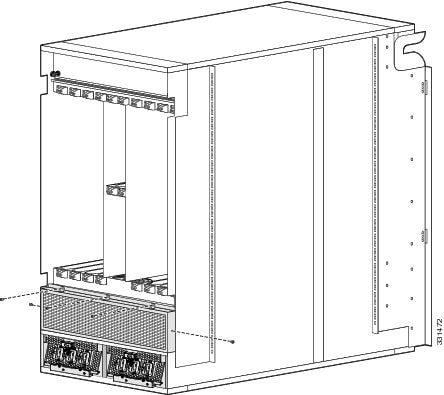
|
1 |
Rear exhaust grille |
| Step 1 | Attach the ESD-preventive wrist strap to your wrist and connect its leash to one of the ESD connection sockets on the rear (MSC) side of the chassis or a bare metal surface on the chassis. |
| Step 2 | Attach the rear exhaust grille to the rear of the chassis using the five panel fasteners. Tighten the three screws on top with a # 2 Phillips screwdriver. Hand-tighten the two screws on the side. |
Installing an Upper Fan Tray
This section describes how to install a fan tray in the upper fan tray slot of the Cisco CRS 8-Slot Line Card Chassis Enhanced router. For information on the chassis airflow and circulation, see c_About_Line_Card_Chassis_Airflow_1041304.xml#con_1041304.
A Cisco CRS 8-Slot Line Card Chassis Enhanced router fan tray operates in either the upper or lower fan tray slot. Each fan tray installs into the rear (MSC) side of the chassis (see #con_1028849/fig_1041545).
Prerequisites
There are no prerequisites for this task.
Required Tools and Equipment
You need the following tools and parts to perform this task:
- ESD-preventive wrist strap
- Number 2 Phillips screwdriver
- Fan tray
Steps
To install an upper fan tray, follow these steps:
| Step 1 | Attach the ESD-preventive wrist strap to your wrist and connect its leash to one of the ESD connection sockets on the rear (MSC) side of the chassis or a bare metal surface on the chassis. | ||
| Step 2 | Using the screwdriver, unscrew the two captive screws holding the fan tray bay door in place. | ||
| Step 3 | Lift the door up; you may need a second person to hold it in the open position. | ||
| Step 4 |
Using two hands to support the fan tray, position it in front of the fan tray bay so that the rails on the sides of the fan tray are aligned with the rail guides on the interior of the chassis.
| ||
| Step 5 |
Slide the fan tray into the fan tray bay. Stop when the fan tray meets the chassis connector in the back of the fan tray bay.
Notice that the tray (and rail guides) drop just inside the fan tray bay door, so that the fan tray “drops” into its final position as it gets almost all the way into the chassis.
| ||
| Step 6 |
Firmly push on the fan tray to seat the fan tray connector in the chassis connector.
| ||
| Step 7 | Lower the fan tray bay door and tighten the two captive screws on the fan tray bay door. |
Upgrading Fan Trays-Summary Steps
Note | The new fan trays (CRS-8-FANTRAY-B) are only supported if you are using Cisco IOS-XR release 4.3.2 or later. |
The following section describes how to upgrade upper and lower legacy fan trays (CRS-8-LCC-FAN-TR) to the new fan trays (CRS-8-FANTRAY-B). This section covers the following topics:
Note | You can use either the legacy or the new fan trays in the Cisco CRS 8-Slot Line Card Chassis Enhanced router. A mix of fan trays is not a supported mode of operation. Such a mode is temporarily allowed only during the fan tray upgrade. |
Prerequisites
The upgrading process is slightly different, depending upon which Cisco IOS-XR release you are using.
- If you are using a Cisco IOS-XR release prior to 5.1.1, follow all of the #task_1088779/_1088802 and #task_1088779/_1088792 below, also the steps in the c_Verifying_the_Fan_Tray_1088853.xml#con_1088853 section.
- If you are using the Cisco IOS-XR release 5.1.1 or later, follow only these steps: #task_1088779/_1088823 and #task_1088779/_1089946 in the #task_1088779/_1088802, which correspond to Step 5 and Step 6 in the #task_1088779/_1088792. Also follow the steps in the c_Verifying_the_Fan_Tray_1088853.xml#con_1088853 section.
Required Tools and Equipment
You need the following tools to perform this task:
Summary Steps
| Step 1 | Shut down the
envmon and envmon_mon processes.
| ||
| Step 2 | Replace the upper fan tray with the new fan tray. | ||
| Step 3 | Replace the lower fan tray with the new fan tray. | ||
| Step 4 | Start the envmon and envmon_mon processes again. | ||
| Step 5 | Wait for 20 seconds, then restart the invmgr process. |
Upgrading Fan Trays-Detailed Steps
Verifying the Fan Tray
To verify which fan tray is installed, run the following commands:
- admin show diag fans
- admin show inventory fans
Example of admin show diag fans for new fan trays
RP/0/RP0/CPU0:ios#admin show diag fans
Rack 0 - Fan Tray 0 (Upper): CRS 8 Slots Fan Tray for CRS-8/S-B
  MAIN:  board type 900163
         800-39053-01 rev 05
         dev N/A
         S/N FLAM16370WNU
  PCA:   73-14855-01 rev 05
  PID:   CRS-8-FANTRAY-B
  VID:   V00
  CLEI:
  ECI:   0
Rack 0 - Fan Tray 1 (Lower): CRS 8 Slots Fan Tray for CRS-8/S-B
  MAIN:  board type 900163
         800-39053-01 rev 05
         dev N/A
         S/N FLM17035W2A
  PCA:   73-14855-01 rev 05
  PID:   CRS-8-FANTRAY-B
  VID:   V00
  CLEI:
  ECI:   0
Example of admin show diag fans for legacy fan trays
RP/0/RP0/CPU0:ios#admin show diag fans
Rack 0 - Fan Tray 0 (Upper): Cisco CRS-1 Series Fan Tray for 8 slots LCC
  MAIN:  board type 900160
         800-23275-09 rev D0
         dev N/A
         S/N TBM16492777
  PCA:   73-8701-06 rev A0
  PID:   CRS-8-LCC-FAN-TR
  VID:   V05
  CLEI:  IPPQAH1JAA
  ECI:   155763
Rack 0 - Fan Tray 1 (Lower): Cisco CRS-1 Series Fan Tray for 8 slots LCC
  MAIN:  board type 900160
         800-23275-09 rev D0
         dev N/A
         S/N TBM16492767
  PCA:   73-8701-06 rev A0
  PID:   CRS-8-LCC-FAN-TR
  VID:   V05
  CLEI:  IPPQAH1JAA
  ECI:   155763
Example of admin show inventory fans for new fan trays
RP/0/RP0/CPU0:ios#admin show inventory fans
NAME: "Rack 0 - Fan Tray Upper", DESCR: "CRS 8 Slots Fan Tray for CRS-8/S-B"
PID: CRS-8-FANTRAY-B, VID: V00, SN: FLAM16370WNU
NAME: "Rack 0 - Fan Tray Lower", DESCR: "CRS 8 Slots Fan Tray for CRS-8/S-B"
PID: CRS-8-FANTRAY-B, VID: V00, SN: FLM17035W2A
Example of admin show inventory fans for legacy fan trays
RP/0/RP0/CPU0:ios#admin show inventory fans
NAME: "Rack 0 - Fan Tray Upper", DESCR: "Cisco CRS-1 Series Fan Tray for 8 slots LCC"
PID: CRS-8-LCC-FAN-TR, VID: V05, SN: TBM16492777
NAME: "Rack 0 - Fan Tray Lower", DESCR: "Cisco CRS-1 Series Fan Tray for 8 slots LCC"
PID: CRS-8-LCC-FAN-TR, VID: V05, SN: TBM16492767
 Feedback