- Preface
- Installation Roadmap Overview
- Cisco CRS 16-Slot Line Card Chassis Enhanced Router
- Installing Power Components
- Installing and Removing Air Circulation Components
- Installing Exterior Cosmetic Components
- Installing Line Cards, PLIMs, and Associated Components
- Removing Chassis Components
- Upgrading Chassis Components
- Cisco CRS 16-Slot EC Line Card Chassis Specifications
- Product IDs
- Removing Line Cards, PLIMs and Associated Components
Removing Chassis
Components
This chapter provides instructions on how to remove components from the Cisco CRS Enhanced 16-Slot Line Card Chassis.
This chapter presents the following topics:
- Removing Line Cards, PLIMs and Associated Components
- Removing the Rear (MSC) Side Cosmetic Components
- Removing the Front (PLIM) Side Cosmetic Components
- Replacing Air Circulation Components
- Removing Power Components
- Converting from One Power System to the Other
Removing Line Cards, PLIMs and Associated Components
This section provides instructions on how to remove the Cisco CRS Series Enhanced 16-Slot Line Card Chassis (LCC) cards, physical layer interface modules (PLIMs), and any associated components.
For general information about installing and removing cards, PLIMs, and associated components, see the About Installing and Removing Cards and Associated Components.
For information on installing and removing the slot covers and impedance carriers, see the Installing or Removing a Slot Cover and the Installing or Removing an Impedance Carrier.
This section presents the following topics:
- Removing a Switch Fabric Card
- Removing an MSC, FP, or LSP Line Card
- Removing a Fan Controller Card
- Removing an RP, PRP, or DRP Card
- Removing a PLIM
- Removing a Hard Drive
- Removing an RP PCMCIA Card
- Removing Optical Modules
- Removing a Cable Management Bracket
Removing a Switch Fabric Card
This section describes how to remove a switch fabric card (SFC) from the Cisco CRS Series Enhanced 16-Slot Line Card Chassis. For more detailed information on the different types of switch fabric cards available and details on the cards themselves, see Cisco CRS Series Enhanced 16-Slot Line Card Chassis System Description.
 Note | Some switch fabric cards (SFCs) contain Class 1 lasers, while others contain Class 1M lasers; for details on the specifics of your card, see Cisco CRS Series Enhanced 16-Slot Line Card Chassis System Description. |
Class 1 Laser Product. Statement 113
Because invisible radiation may be emitted from the aperture of the port when no fiber cable is connected, avoid exposure to radiation and do not stare into open apertures. Statement 125
 Caution | Class 1M laser radiation when open. Do not view directly with optical instruments. Statement 281 |
For diverging beams, viewing the laser output with certain optical instruments within a distance of 100 mm may pose an eye hazard. For collimated beams, viewing the laser output with certain optical instruments designed for use at a distance may pose an eye hazard. Statement 282
Laser radiation. Do not view directly with optical instruments. Class 1M laser product. Statement 283
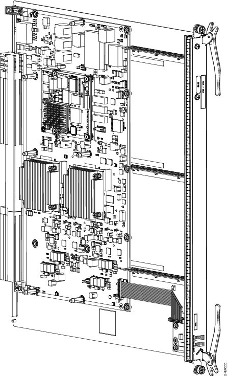
The following image shows an example of a switch fabric card (in this case, an FQ123-140G SFC).
Prerequisites
Before performing this task, open the front (PLIM) side cosmetic doors, if installed.
Required Tools and Equipment
You need the following tools to perform this task:
- ESD-preventive wrist strap
- Number 2 Phillips screwdriver or number 2 common (flat head) screwdriver
Steps
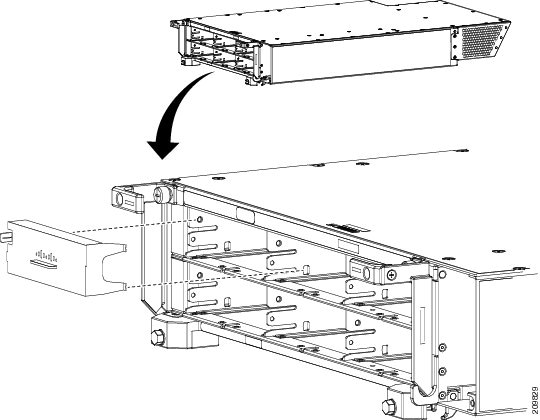
To remove a switch fabric card, see the image below and perform the following steps:
Note | In the switch fabric card removal image below, an Impedance Carrier is shown. Refer to image FQ123 -140G Switch Fabric Card above for an example of the actual switch fabric card. |
|
1 |
Captive screw |
3 |
Direction of installation or removal |
|
2 |
Ejector lever |
|
|
1. Attach the ESD-preventive wrist strap to your wrist and connect its leash to one of the ESD connection sockets: on the front (PLIM) side of the chassis there is one ESD connection socket right above the fan controllers. On the rear (MSC) side of the chassis there are two ESD connection sockets right above the cable management tray in the center of the chassis (left and right). You can also connect the ESD-preventive wrist strap leash to any bare metal surface on the chassis.
2. Identify the switch fabric card to be removed from the card cage. Use the number 2 Phillips screwdriver or number 2 common (flat head) screwdriver to turn the two captive screws on the front panel of the card counterclockwise to loosen it from the slot.
3. Grasp the two card ejector levers and simultaneously pivot both ejector levers 90 degrees (70 degrees for a newer switch fabric card) away from the front edge of the card carrier to unseat the card from the midplane connector.
4. Touching only the metal card carrier, slide the card from the slot and place it directly into an antistatic sack or other ESD-preventive container. If you plan to return the defective card to the factory, repackage it in its original shipping container.
DETAILED STEPS
What to Do Next
After performing this task, close the front (PLIM) side cosmetic doors, if installed. If you need to install a new switch fabric card, see the Installing a Switch Fabric Card.
Removing an MSC, FP, or LSP Line Card
This section describes how to remove a line card from the Cisco CRS Series Enhanced 16-Slot Line Card Chassis. For more detailed information on the line cards, see Cisco CRS Series Enhanced 16-Slot Line Card Chassis System Description.
Prerequisites
Before performing this task, open the cosmetic doors, if installed.
Caution | Do not use the faceplate bracket to pull a line card from the slot; you could cause serious damage to the line card. |
Caution | Remove or install only one modular services card at a time. Allow at least 15 seconds for the router to complete the preceding tasks before removing or installing another modular services card. The router may indicate a hardware failure if you do not follow proper procedures. |
Required Tools and Equipment
You need the following tools and part to perform this task:
- ESD-preventive strap
- Number 2 Phillips screwdriver or number 2 common (flat head) screwdriver
- MSC Impedance carrier (Cisco product number: CRS-MSC-IMPEDANCE=)
Steps
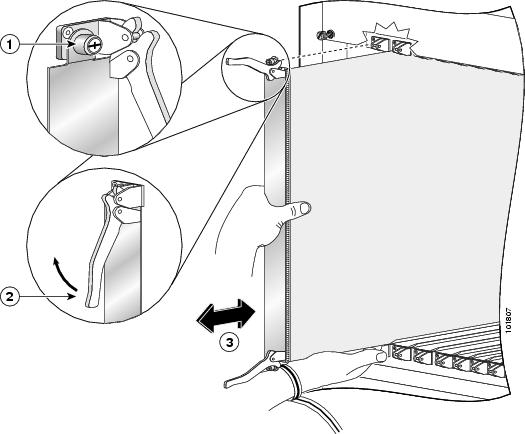
To remove a line card, see the image below and perform the following steps:
|
1 |
Captive screw |
3 |
Direction of installation or removal |
|
2 |
Ejector lever |
|
|
1. Attach the ESD-preventive wrist strap to your wrist and connect its leash to one of the ESD connection sockets: on the front (PLIM) side of the chassis there is one ESD connection socket right above the fan controllers. On the rear (MSC) side of the chassis there are two ESD connection sockets right above the cable management tray in the center of the chassis (left and right). You can also connect the ESD-preventive wrist strap leash to any bare metal surface on the chassis.
2. Use a number 2 Phillips screwdriver or number 2 common (flat head) screwdriver to loosen the captive screw next to each line card ejector lever.
3. Simultaneously pivot the ejector levers away from the faceplate to release the line card from the midplane connectors.
4. Grasp the ejector levers with both hands and gently pull the line card halfway from the slot. Do not use the bracket to pull the line card from the slot.
5. Move one hand under the line card to guide it. Avoid touching the line card printed circuit board, components, or any connector pins.
6. Place the removed line card on an antistatic mat, or immediately place it in an antistatic bag if you plan to return it to the factory.
7. If the line card slot is to remain empty, install an MSC impedance carrier to keep dust out of the chassis and to maintain proper airflow through the line card compartment.
8. Use a number 2 Phillips screwdriver or number 2 common (flat head) screwdriver to tighten the captive screws next to each impedance carrier ejector lever to ensure proper EMI shielding and maintain proper airflow throughout the chassis.
DETAILED STEPS
What to Do Next
After performing this task, close the rear (MSC) side cosmetic doors, if installed. If you need to install a new MSC, FP, or LSP Line Card, see the Installing an MSC, FP, or LSP Line Card.
Removing a Fan Controller Card
This section describes how to remove a fan controller card from the Cisco CRS Series Enhanced 16-Slot Line Card Chassis. For more detailed information on the Cisco CRS Series Enhanced 16-Slot Line Card Chassis fan controller card, see Cisco CRS Series Enhanced 16-Slot Line Card Chassis System Description.
Two Cisco CRS Series Enhanced 16-Slot Line Card Chassis fan controller cards, exist in every Cisco CRS Series Enhanced 16-Slot Line Card Chassis.
Prerequisites
Before performing this task, open the front (PLIM) side cosmetic doors, if installed.
Required Tools and Equipment
You need the following tools to perform this task:
- ESD-preventive wrist strap
- Number 2 Phillips screwdriver or number 2 common (flat head) screwdriver
Steps
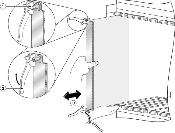
To remove a Cisco CRS Series Enhanced 16-Slot Line Card Chassis fan controller card, see the image below and perform the following steps:
|
1 |
Captive screw |
3 |
Direction of installation or removal |
|
2 |
Ejector lever |
|
|
1. Attach the ESD-preventive wrist strap to your wrist and connect its leash to one of the ESD connection sockets: on the front (PLIM) side of the chassis there is one ESD connection socket right above the fan controllers. On the rear (MSC) side of the chassis there are two ESD connection sockets right above the cable management tray in the center of the chassis (left and right). You can also connect the ESD-preventive wrist strap leash to any bare metal surface on the chassis.
2. Identify the Cisco CRS Series Enhanced 16-Slot Line Card Chassis fan controller card to be removed from the card cage. Use the number 2 Phillips screwdriver or number 2 common (flat head) screwdriver to turn the two captive screws on the front panel of the card counterclockwise to loosen it from the slot.
3. Grasp the two card ejector levers and simultaneously pivot both ejector levers 90 degrees (70 degrees for a new Cisco CRS Series Enhanced 16-Slot Line Card Chassis fan controller card) away from the front edge of the card carrier to unseat the card from the midplane connector.
4. Touching only the metal card carrier, slide the card from the slot and place it directly into an antistatic sack or other ESD-preventive container. If you plan to return the defective card to the factory, repackage it in its original packaging.
DETAILED STEPS
| Step 1 | Attach the ESD-preventive wrist strap to your wrist and connect its leash to one of the ESD connection sockets: on the front (PLIM) side of the chassis there is one ESD connection socket right above the fan controllers. On the rear (MSC) side of the chassis there are two ESD connection sockets right above the cable management tray in the center of the chassis (left and right). You can also connect the ESD-preventive wrist strap leash to any bare metal surface on the chassis. |
| Step 2 | Identify the Cisco CRS Series Enhanced 16-Slot Line Card Chassis fan controller card to be removed from the card cage. Use the number 2 Phillips screwdriver or number 2 common (flat head) screwdriver to turn the two captive screws on the front panel of the card counterclockwise to loosen it from the slot. |
| Step 3 | Grasp the two card ejector levers and simultaneously pivot both ejector levers 90 degrees (70 degrees for a new Cisco CRS Series Enhanced 16-Slot Line Card Chassis fan controller card) away from the front edge of the card carrier to unseat the card from the midplane connector. |
| Step 4 | Touching only the metal card carrier, slide the card from the slot and place it directly into an antistatic sack or other ESD-preventive container. If you plan to return the defective card to the factory, repackage it in its original packaging. |
What to Do Next
After performing this task, close the front (PLIM) side cosmetic doors. If you need to install a new fan controller card, see the Installing a Cisco CRS Series Enhanced 16-Slot Line Card Chassis Fan Controller Card.
Removing an RP, PRP, or DRP Card
This section describes how to remove a route processor (RP), performance route processor (PRP), or distributed route processor (DRP) card from the Cisco CRS Series Enhanced 16-Slot Line Card Chassis. For more detailed information on the route processor card, see the Installing an RP, PRP, or DRP Card or Cisco CRS Series Enhanced 16-Slot Line Card Chassis System Description.
Every Cisco CRS Series Enhanced 16-Slot Line Card Chassis contains two route processor cards in dedicated slots on the PLIM side of the chassis.
Class 1 Laser Product. Statement 113
Because invisible radiation may be emitted from the aperture of the port when no fiber cable is connected, avoid exposure to radiation and do not stare into open apertures. Statement 125
Prerequisites
Because chassis operation may be impacted by the removal of an RP or PRP card, perform these tasks only if one of the following conditions exists:
- When you are certain that the RP card in the chassis is operational and, if not already the Active RP, ready to assume control (this happens automatically)
- When the chassis is undergoing scheduled maintenance
- When the Cisco CRS Series Enhanced 16-Slot Line Card Chassis is powered down
Failure to follow these guidelines can result in interruptions in data communications and network connectivity.
Before performing this task, open the cosmetic doors (if installed).
Required Tools and Equipment
You need the following tools to perform this task:
- ESD-preventive wrist strap
- Number 2 Phillips screwdriver or number 2 common (flat head) screwdriver
Steps
To remove an RP, PRP, or DRP card, perform the following steps:
1. Attach the ESD-preventive wrist strap to your wrist and connect its leash to one of the ESD connection sockets: on the front (PLIM) side of the chassis there is one ESD connection socket right above the fan controllers. On the rear (MSC) side of the chassis there are two ESD connection sockets right above the cable management tray in the center of the chassis (left and right). You can also connect the ESD-preventive wrist strap leash to any bare metal surface on the chassis.
2. Identify the card to be removed from the card cage. Remove any cables connected to the front panel of the card.
3. PRP cards only—Before removing a PRP card, you must first push the OIR button (using a pointed object such as a pen), which causes the blue OIR Ready LED to start blinking. When the board is ready for removal, the blue LED glows solidly.
4. Use the number 2 Phillips screwdriver or number 2 common (flat head) screwdriver to turn the two captive screws on the front panel of the card counterclockwise to loosen the card from the slot.
5. Grasp the two card ejector levers and simultaneously pivot both ejector levers 90 degrees away from the front edge of the card carrier to unseat the card from the backplane connector.
6. Touching only the metal card carrier, slide the card from the slot and place it directly into an antistatic sack or other ESD-preventive container. If you plan to return the defective card to the factory, repackage it in the shipping container you received with the replacement card.
DETAILED STEPS
| Step 1 | Attach the ESD-preventive wrist strap to your wrist and connect its leash to one of the ESD connection sockets: on the front (PLIM) side of the chassis there is one ESD connection socket right above the fan controllers. On the rear (MSC) side of the chassis there are two ESD connection sockets right above the cable management tray in the center of the chassis (left and right). You can also connect the ESD-preventive wrist strap leash to any bare metal surface on the chassis. |
| Step 2 | Identify the card to be removed from the card cage. Remove any cables connected to the front panel of the card. |
| Step 3 | PRP cards only—Before removing a PRP card, you must first push the OIR button (using a pointed object such as a pen), which causes the blue OIR Ready LED to start blinking. When the board is ready for removal, the blue LED glows solidly. |
| Step 4 | Use the number 2 Phillips screwdriver or number 2 common (flat head) screwdriver to turn the two captive screws on the front panel of the card counterclockwise to loosen the card from the slot. |
| Step 5 | Grasp the two card ejector levers and simultaneously pivot both ejector levers 90 degrees away from the front edge of the card carrier to unseat the card from the backplane connector. |
| Step 6 | Touching only the metal card carrier, slide the card from the slot and place it directly into an antistatic sack or other ESD-preventive container. If you plan to return the defective card to the factory, repackage it in the shipping container you received with the replacement card. |
What to Do Next
After performing this task, close the front (PLIM) side cosmetic doors (if installed). If you need to install a new RP, DRP, or PRP card, see the Installing an RP, PRP, or DRP Card.
Removing a PLIM
This section describes how to remove a PLIM from the Cisco CRS Series Enhanced 16-Slot Line Card Chassis.
Note | Some PLIMs contain Class 1 lasers, while others contain Class 1M lasers; for details of your PLIM, see Cisco CRS Series Enhanced 16-Slot Line Card Chassis System Description. |
Class 1 Laser Product. Statement 113
Because invisible radiation may be emitted from the aperture of the port when no fiber cable is connected, avoid exposure to radiation and do not stare into open apertures. Statement 125
Caution | Class 1M laser radiation when open. Do not view directly with optical instruments. Statement 281 |
For diverging beams, viewing the laser output with certain optical instruments within a distance of 100 mm may pose an eye hazard. For collimated beams, viewing the laser output with certain optical instruments designed for use at a distance may pose an eye hazard. Statement 282
Laser radiation. Do not view directly with optical instruments. Class 1M laser product. Statement 283
Caution | The following warning applies to removing very-short-reach (VSR) PLIMs: The router may indicate a hardware failure if you do not follow proper procedures. Remove or install only one PLIM at a time. Allow at least 15 seconds for the router to complete the preceding tasks before removing or installing another PLIM. |
Prerequisites
Before performing this task, open the front (PLIM) side cosmetic doors (if installed).
Caution | The system can indicate a hardware failure if you do not follow proper procedures. Remove or install only one PLIM at a time. Allow at least 15 seconds for the system to complete the preceding tasks before removing or installing another PLIM. |
Note | We strongly recommend that you use the Cisco IOS XR shutdown command before removing a PLIM to prevent anomalies when you reinstall a new or reconfigured PLIM. |
Required Tools and Equipment
You need the following tools to perform this task:
- ESD-preventive wrist strap
- Number 2 Phillips screwdriver or number 2 common (flat head) screwdriver
Steps
To remove a PLIM, see the image below and perform the following steps:
|
1 |
Captive screw |
3 |
Direction of installation or removal |
|
2 |
Ejector lever |
|
|
1. Attach the ESD-preventive wrist strap to your wrist and connect its leash to one of the ESD connection sockets: on the front (PLIM) side of the chassis there is one ESD connection socket right above the fan controllers. On the rear (MSC) side of the chassis there are two ESD connection sockets right above the cable management tray in the center of the chassis (left and right). You can also connect the ESD-preventive wrist strap leash to any bare metal surface on the chassis.
2. Identify the card to be replaced.
3. Use the number 2 Phillips screwdriver or number 2 common (flat head) screwdriver to loosen the two captive screws holding the card in place.
4. Grasp the two card ejector levers and simultaneously pivot both ejector levers 90 degrees (70 degrees for a newer PLIM) away from the front edge of the card carrier to unseat the card from the backplane connector.
5. Touching only the metal card carrier, slide the card from the slot and place it directly into an antistatic sack or other ESD-preventive container.
DETAILED STEPS
| Step 1 | Attach the ESD-preventive wrist strap to your wrist and connect its leash to one of the ESD connection sockets: on the front (PLIM) side of the chassis there is one ESD connection socket right above the fan controllers. On the rear (MSC) side of the chassis there are two ESD connection sockets right above the cable management tray in the center of the chassis (left and right). You can also connect the ESD-preventive wrist strap leash to any bare metal surface on the chassis. |
| Step 2 | Identify the card to be replaced. |
| Step 3 | Use the number 2 Phillips screwdriver or number 2 common (flat head) screwdriver to loosen the two captive screws holding the card in place. |
| Step 4 | Grasp the two card ejector levers and simultaneously pivot both ejector levers 90 degrees (70 degrees for a newer PLIM) away from the front edge of the card carrier to unseat the card from the backplane connector. |
| Step 5 | Touching only the metal card carrier, slide the card from the slot and place it directly into an antistatic sack or other ESD-preventive container. |
What to Do Next
Because invisible
laser radiation may be emitted from the aperture of the port when no cable is
connected, avoid exposure to laser radiation and do not stare into open
apertures. Statement 70
Some PLIMs contain Class 1 lasers and some contain Class 1M. See the documentation for the specific PLIM for details.
What to Do Next
After performing this task, close the front (PLIM) side cosmetic doors (if installed). If you need to install a new PLIM, see Installing a PLIM.
Removing a Hard Drive
This section describes how to remove a hard drive from an RP or a DRP PLIM. Hard drives are available as an option on both the RP and DRP PLIM and are removed in the same manner. For more detailed information on the hard drives, see the About Hard Drives and PCMCIA Cards, or Cisco CRS Series Enhanced 16-Slot Line Card Chassis System Description . Installing a Card-Based Hard Drive shows the hard drive door location on the RP card. (The hard drive for the DRP PLIM is in a similar location.)
Prerequisites
The hard disk should be powered down prior to removal. This reduces the chances of data corruption. To power down the hard disk prior to removal, use the proc mandatory off hd_drv and proc shutdown hd_drv commands.
Before performing this task, open the front (PLIM) side cosmetic doors (if installed).
Required Tools and Equipment
You need the following tools to perform this task:
- ESD-preventive strap
- Number 2 Phillips screwdriver or number 2 common (flat head) screwdriver
Steps
To remove the hard drive, perform the following steps:
1. Attach the ESD-preventive wrist strap to your wrist and connect its leash to one of the ESD connection sockets: on the front (PLIM) side of the chassis there is one ESD connection socket right above the fan controllers. On the rear (MSC) side of the chassis there are two ESD connection sockets right above the cable management tray in the center of the chassis (left and right). You can also connect the ESD-preventive wrist strap leash to any bare metal surface on the chassis.
2. Use the number 2 Phillips screwdriver or number 2 common (flat head) screwdriver to loosen the captive screws at the left and right of the hard drive door on the faceplate of the card. If needed, use a number 2 Phillips screwdriver or number 2 common (flat head) screwdriver on the captive screws.
3. Remove the hard drive door and set it carefully aside.
4. Press the release button to unseat the hard drive sled from the card.
5. Carefully pull the hard drive sled from the card.
6. Place the removed hard drive on an antistatic mat, or immediately place it in an antistatic bag if you plan to return it to the factory.
7. If the hard drive slot is to remain empty, replace the door to keep dust out, and tighten the captive screws.
DETAILED STEPS
| Step 1 | Attach the ESD-preventive wrist strap to your wrist and connect its leash to one of the ESD connection sockets: on the front (PLIM) side of the chassis there is one ESD connection socket right above the fan controllers. On the rear (MSC) side of the chassis there are two ESD connection sockets right above the cable management tray in the center of the chassis (left and right). You can also connect the ESD-preventive wrist strap leash to any bare metal surface on the chassis. |
| Step 2 | Use the number 2 Phillips screwdriver or number 2 common (flat head) screwdriver to loosen the captive screws at the left and right of the hard drive door on the faceplate of the card. If needed, use a number 2 Phillips screwdriver or number 2 common (flat head) screwdriver on the captive screws. |
| Step 3 | Remove the hard drive door and set it carefully aside. |
| Step 4 | Press the release button to unseat the hard drive sled from the card. |
| Step 5 | Carefully pull the hard drive sled from the card. |
| Step 6 | Place the removed hard drive on an antistatic mat, or immediately place it in an antistatic bag if you plan to return it to the factory. |
| Step 7 | If the hard drive slot is to remain empty, replace the door to keep dust out, and tighten the captive screws. |
What to Do Next
Close the front (PLIM) side cosmetic doors (if installed). If you need to install a new hard drive, see the Installing a Card-Based Hard Drive.
Removing an RP PCMCIA Card
This section describes how to install a PCMCIA card in an RP or a DRP card PCMCIA slot. For more detailed information on PCMCIA cards, see the About Hard Drives and PCMCIA Cards, or Cisco CRS Series Enhanced 16-Slot Line Card Chassis System Description. Figure Figure 1 shows you the location of the PCMCIA door in the RP card faceplate. (The PCMCIA cards for the DRP are in a similar location).
Prerequisites
Before performing this task, open the front (PLIM) side cosmetic doors (if installed).
Required Tools and Equipment
You need the following tools to perform this task:
- ESD-preventive strap
- Number 2 Phillips screwdriver or number 2 common (flat head) screwdriver
Steps
To remove the PCMCIA card, perform the following steps:
1. Attach the ESD-preventive wrist strap to your wrist and connect its leash to one of the ESD connection sockets: on the front (PLIM) side of the chassis there is one ESD connection socket right above the fan controllers. On the rear (MSC) side of the chassis there are two ESD connection sockets right above the cable management tray in the center of the chassis (left and right). You can also connect the ESD-preventive wrist strap leash to any bare metal surface on the chassis.
2. Using the number 2 Phillips screwdriver or number 2 common (flat head) screwdriver, loosen the captive screw at the bottom of the PCMCIA slot door on the faceplate of the card.
3. While lifting the hinged PCMCIA slot door up, press the release button for the card slot to disengage the card from the card, and then carefully pull out the far left removable PCMCIA flash card.
4. Place the removed PCMCIA card on an antistatic mat, or immediately place it in an antistatic bag if you plan to return it to the factory.
5. If the PCMCIA card slot is to remain empty, close the door to keep dust out, and tighten the captive screw with the number 2 Phillips screwdriver or number 2 common (flat head) screwdriver. Otherwise, install the new PCMCIA card.
DETAILED STEPS
| Step 1 | Attach the ESD-preventive wrist strap to your wrist and connect its leash to one of the ESD connection sockets: on the front (PLIM) side of the chassis there is one ESD connection socket right above the fan controllers. On the rear (MSC) side of the chassis there are two ESD connection sockets right above the cable management tray in the center of the chassis (left and right). You can also connect the ESD-preventive wrist strap leash to any bare metal surface on the chassis. |
| Step 2 | Using the number 2 Phillips screwdriver or number 2 common (flat head) screwdriver, loosen the captive screw at the bottom of the PCMCIA slot door on the faceplate of the card. |
| Step 3 | While lifting the hinged PCMCIA slot door up, press the release button for the card slot to disengage the card from the card, and then carefully pull out the far left removable PCMCIA flash card. |
| Step 4 | Place the removed PCMCIA card on an antistatic mat, or immediately place it in an antistatic bag if you plan to return it to the factory. |
| Step 5 | If the PCMCIA card slot is to remain empty, close the door to keep dust out, and tighten the captive screw with the number 2 Phillips screwdriver or number 2 common (flat head) screwdriver. Otherwise, install the new PCMCIA card. |
What to Do Next
Close the front (PLIM) side cosmetic doors (if installed). If you intend to install a new PCMCIA card, see the Installing a PCMCIA Card.
Removing Optical Modules
Refer to the Cisco CRS Carrier Routing System Ethernet Physical Layer Interface Module Installation Note for information on how to install or remove SFP, XFP, and other modules for your PLIM.
Because invisible laser radiation may be emitted from the aperture of the port when no cable is connected, avoid exposure to laser radiation and do not stare into open apertures. Statement 70
Note | After removing a PLIM, be sure to replace any front (PLIM) side cover plates. |
Removing a Cable Management Bracket
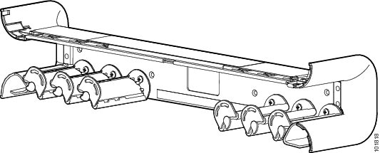
This section describes how to remove a cable management bracket in the Cisco CRS Series Enhanced 16-Slot Line Card Chassis.
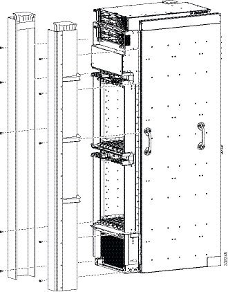
The horizontal cable management brackets provide cable management capabilities for the MSCs and PLIMs on the Cisco CRS Series Enhanced 16-Slot Line Card Chassis. The following image shows a midchassis cable management bracket. The installed on the front (PLIM) side of the chassis.
Prerequisites
The cable management bracket arrives pre-installed on the chassis. Before performing this task, open the cosmetic doors (if installed) and remove any cables from the bracket.
Required Tools and Equipment
You need the following tools to perform this task:
- ESD-preventive wrist strap
- Number 2 Phillips screwdriver or number 2 common (flat head) screwdriver
Steps
To remove a cable management bracket, perform the following steps:
1. Attach the ESD-preventive wrist strap to your wrist and connect its leash to one of the ESD connection sockets: on the front (PLIM) side of the chassis there is one ESD connection socket right above the fan controllers. On the rear (MSC) side of the chassis there are two ESD connection sockets right above the cable management tray in the center of the chassis (left and right). You can also connect the ESD-preventive wrist strap leash to any bare metal surface on the chassis.
2. Use the number 2 Phillips screwdriver or number 2 common (flat head) screwdriver to loosen and remove the four screws holding the bracket to the chassis.
3. Set the bracket carefully aside.
DETAILED STEPS
| Step 1 | Attach the ESD-preventive wrist strap to your wrist and connect its leash to one of the ESD connection sockets: on the front (PLIM) side of the chassis there is one ESD connection socket right above the fan controllers. On the rear (MSC) side of the chassis there are two ESD connection sockets right above the cable management tray in the center of the chassis (left and right). You can also connect the ESD-preventive wrist strap leash to any bare metal surface on the chassis. |
| Step 2 | Use the number 2 Phillips screwdriver or number 2 common (flat head) screwdriver to loosen and remove the four screws holding the bracket to the chassis. |
| Step 3 | Set the bracket carefully aside. |
What to Do Next
You may now install a replacement cable management bracket, if necessary. See the Installing a Cable Management Bracket for more information. Close the cosmetic doors (if installed) after replacing the cable management bracket.
Removing the Rear (MSC) Side Cosmetic Components
This section describes how to remove the rear (MSC) side exterior cosmetic components from the chassis. This section includes all the steps you need to remove all cosmetic parts from the chassis.
This section contains the following procedures:
If you are not using the vertical cable troughs, see the Removing the Upper Rear Air Grille and Rear Kick Plate if Vertical Troughs Are Not Used.
Note | While it is possible to remove most of the rear cosmetic parts on the fabric chassis separately, some parts (such as a vertical cable trough) require that other parts be removed first. |
- Prerequisites
- Required Tools and Equipment
- Steps
- Removing the Upper Rear Air Grille and Rear Kick Plate if Vertical Troughs Are Not Used
- What to Do Next
Prerequisites
Ensure that you have all the original packaging material for the cosmetic components available.
Required Tools and Equipment
You need the following tool to perform this task:
- 8-in. number 1 Phillips screwdriver—magnetic head preferable
Steps
To remove the rear (MSC) side cosmetic components, perform the following steps:
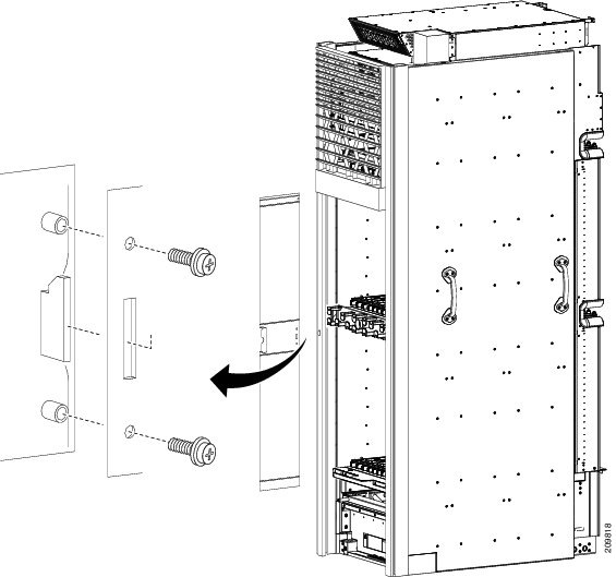
1. (Removing the Rear Doors) Remove the screws from the doors. There are four M4 x 10 screws on each side for the metal sections of the doors and six M4 x 8 screws on each side for the plexiglass section of the door.
2. Lift the doors and set them carefully aside. See the above image.
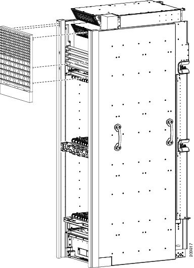
3. (Removing the Upper Rear Air Grille) Follow these steps if you are using the vertical troughs. To remove the upper rear air grille if the vertical troughs are not used, see the Removing the Upper Rear Air Grille and Rear Kick Plate if Vertical Troughs Are Not Used.
4. Release the upper rear air grille from the ball stud retainers.
5. Carefully unhook the hanger brackets from the top of the vertical cable troughs as shown in the following image.
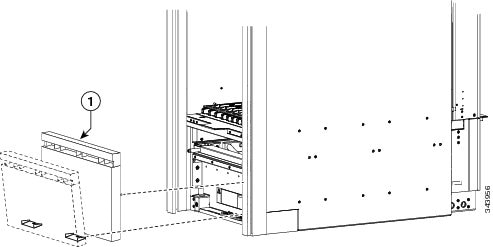
6. (Removing the Rear Kick Plate) Follow these steps if you are using the vertical troughs. To remove the rear kick plate if the vertical troughs are not used, see the Removing the Upper Rear Air Grille and Rear Kick Plate if Vertical Troughs Are Not Used.
7. Release the kick plate from the ball stud retainers.
8. Carefully remove the rear kick plate form the tabs on the bottom as shown in the following image.
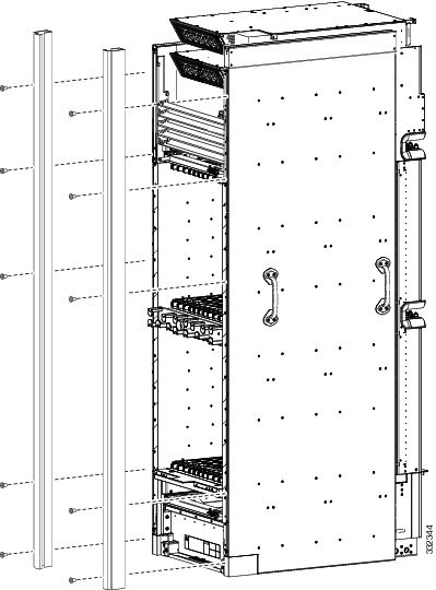
9. (Removing the Rear Vertical Cable Troughs) Remove the rear vertical cable troughs—one left and one right—from the rear of the chassis as shown in the following image.
DETAILED STEPS
| Step 1 | (Removing the
Rear Doors) Remove the screws from the doors. There are four M4 x 10 screws on
each side for the metal sections of the doors and six M4 x 8 screws on each
side for the plexiglass section of the door.
 | ||
| Step 2 | Lift the doors
and set them carefully aside. See the above image.
| ||
| Step 3 | (Removing the Upper Rear Air Grille) Follow these steps if you are using the vertical troughs. To remove the upper rear air grille if the vertical troughs are not used, see the Removing the Upper Rear Air Grille and Rear Kick Plate if Vertical Troughs Are Not Used. | ||
| Step 4 | Release the upper rear air grille from the ball stud retainers. | ||
| Step 5 | Carefully
unhook the hanger brackets from the top of the vertical cable troughs as shown
in the following image.
 | ||
| Step 6 | (Removing the Rear Kick Plate) Follow these steps if you are using the vertical troughs. To remove the rear kick plate if the vertical troughs are not used, see the Removing the Upper Rear Air Grille and Rear Kick Plate if Vertical Troughs Are Not Used. | ||
| Step 7 | Release the kick plate from the ball stud retainers. | ||
| Step 8 | Carefully
remove the rear kick plate form the tabs on the bottom as shown in the
following image.
| ||
| Step 9 | (Removing the
Rear Vertical Cable Troughs) Remove the rear vertical cable troughs—one left
and one right—from the rear of the chassis as shown in the following image.
|
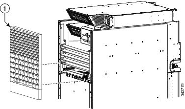
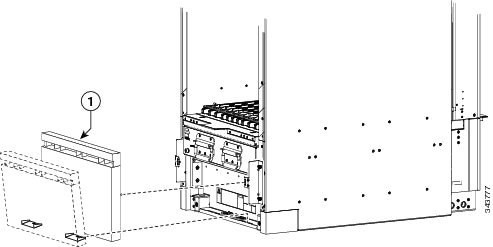
Removing the Upper Rear Air Grille and Rear Kick Plate if Vertical Troughs Are Not Used
If you are using the vertical troughs, see the Removing the Rear (MSC) Side Cosmetic Components.
Note | Because the upper rear air grille is installed at the top of the chassis, it is easier to stand on a ladder while removing it. |
1. To remove the upper rear air grille, unhook it from the brackets and slide upward to release.
2. (Removing the Rear Kick Plate) To remove the rear kick plate, unsnap it from the tabs near the bottom of the chassis.
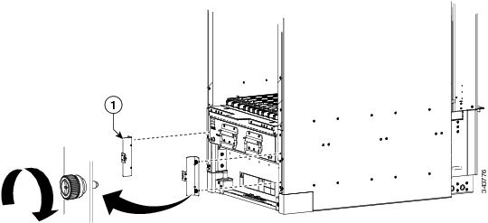
3. To remove the brackets installed with the kick plate, loosen the captive screws that attach the bracket to the chassis.
DETAILED STEPS
| Step 1 | To remove the
upper rear air grille, unhook it from the brackets and slide upward to release.
| ||
| Step 2 | (Removing the
Rear Kick Plate) To remove the rear kick plate, unsnap it from the tabs near
the bottom of the chassis.
| ||
| Step 3 | To remove the
brackets installed with the kick plate, loosen the captive screws that attach
the bracket to the chassis.
|
What to Do Next
Be sure that all parts have been carefully set aside and repackaged appropriately.
Removing the Front (PLIM) Side Cosmetic Components
This section describes how to remove exterior cosmetic components from the front (PLIM) side of the chassis. This section includes all the steps you need to remove all the cosmetic parts from the chassis. To remove a particular part, see the appropriate step or steps in the procedure that follows.
Note | While it is possible to remove most of the cosmetic parts on the Cisco CRS Series Enhanced 16-slot Line Card Chassis separately, some parts (such as a unistrut) require that other parts be removed first. |
This section describes how to perform the following tasks:
Prerequisites
Ensure that you have all the original packaging material for the cosmetic components available.
Required Tools and Equipment
You need the following tools to perform this task:
- 8-in. long number 1 Phillips screwdriver—magnetic head preferable, bit size number 1
- 13-mm socket
- 2-mm hex key wrench (for door set screws)
- T8 Torx wrench (for removing upper grille support)
Steps
To remove the front (PLIM) side external cosmetic components, perform the following steps:
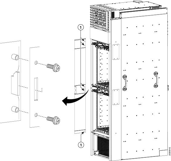
1. (Removing the Front Doors) Remove the screws from the doors. There are five M4 x 10 screws on each side for the metal sections of the doors and six M4 x 8 screws on each side for the plexiglass section of the door.
2. Lift the doors and set them carefully aside. See the following image.
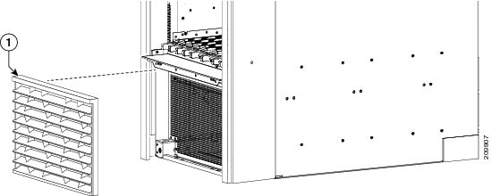
3. (Removing the Front Lower Grille) Remove the front lower grille (see the following image) by unsnapping the top portion from the ball stud snaps on the grille frame.
4. Rotate the grille towards you on its brackets, and then lift it clear of the support, and set it carefully aside.
5. (Removing the Front Upper Grille) Remove the upper grille (see the following image) by unsnapping the bottom portion from the ball stud snaps on the chassis.
6. Rotate the grille towards you on its hook hanger brackets, then lift it clear of the support, and set it carefully aside.
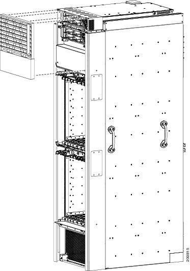
7. (Removing the Default Front Vertical Cable Troughs) Remove the default vertical cable troughs (see the following image)—one right and one left—from the front (PLIM) side of the chassis:
8. (Removing the Optional Wide Front Vertical Cable Troughs) Remove the wide vertical cable troughs—one right and one left—from the front (PLIM) side of the chassis:
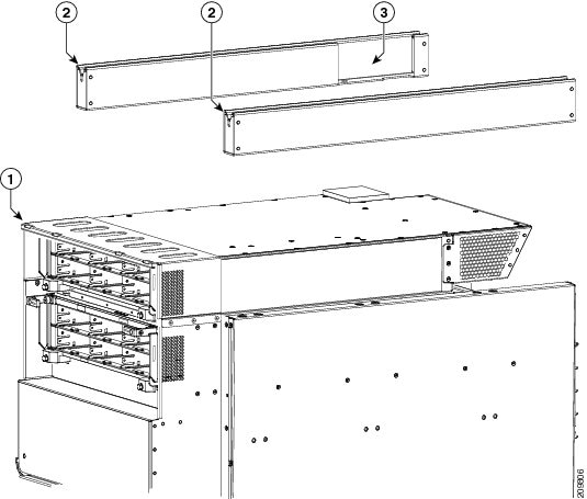
9. (Removing the Unistruts) Use the 13-mm socket and ratchet wrench to remove the four M12 hex head bolts and washers, two on each unistrut, that attach the unistrut to the top of the chassis.
DETAILED STEPS
| Step 1 |
(Removing the Front Doors) Remove the screws from the doors. There are five M4 x 10 screws on each side for the metal sections of the doors and six M4 x 8 screws on each side for the plexiglass section of the door.
| ||||||||
| Step 2 | Lift the doors and set them carefully aside. See the following image.
 | ||||||||
| Step 3 | (Removing the Front Lower Grille) Remove the front lower grille (see the following image) by unsnapping the top portion from the ball stud snaps on the grille frame. | ||||||||
| Step 4 |
Rotate the grille towards you on its brackets, and then lift it clear of the support, and set it carefully aside.
 | ||||||||
| Step 5 | (Removing the Front Upper Grille) Remove the upper grille (see the following image) by unsnapping the bottom portion from the ball stud snaps on the chassis. | ||||||||
| Step 6 |
Rotate the grille towards you on its hook hanger brackets, then lift it clear of the support, and set it carefully aside.
 | ||||||||
| Step 7 | (Removing the Default Front Vertical Cable Troughs) Remove the default vertical cable troughs (see the following image)—one right and one left—from the front (PLIM) side of the chassis:
| ||||||||
| Step 8 |
(Removing the Optional Wide Front Vertical Cable Troughs) Remove the wide vertical cable troughs—one right and one left—from the front (PLIM) side of the chassis:
| ||||||||
| Step 9 | (Removing the Unistruts) Use the 13-mm socket and ratchet wrench to remove the four M12 hex head bolts and washers, two on each unistrut, that attach the unistrut to the top of the chassis.
|
What to Do Next
Be sure that all parts have been carefully set aside and repackaged as appropriate.
Replacing Air Circulation Components
This section provides instructions on how to install and replace the Cisco CRS Series Enhanced 16-Slot Line Card Chassis air circulation components.
Note | The chassis is shipped with the fan trays and air filter pre-installed. |
This section presents the following topics:
- Information About the Air Circulation Components
- How to Replace Air Circulation Components
- Prerequisites
- Required Tools and Equipment
Information About the Air Circulation Components
This section contains some general information about the air circulation components in the following topics:
About the Fan Trays
The Cisco CRS Series Enhanced 16-Slot Line Card Chassis has two fan trays , one just below the lower card cage and the other just above the upper card cage. The chassis can run with only one fan tray operating. If a failure occurs in one fan tray, the other fan tray acts as the redundant fan tray to assure fault-tolerant system performance; the chassis continues to operate while the failed fan tray is replaced.
The Cisco CRS Series Enhanced 16-Slot Line Card Chassis fan tray operates in either the upper or lower fan tray slots. Each fan tray installs into the rear (MSC) side of the chassis and contains:
- Nine fans
- Fan tray board
- Front-panel status LED
Note | The upper and lower fan trays are interchangeable and installed in the same manner. |

|
1 |
Front (PLIM) side of chassis |
6 |
Power shelves (two installed) |
|
2 |
Air intake |
7 |
Air exhaust |
|
3 |
Lower fan tray |
8 |
Upper card cage |
|
4 |
Air filter |
9 |
Lower card cage |
|
5 |
Upper fan tray |
10 |
Rear [MSC] side of chassis |
About the Air Filter
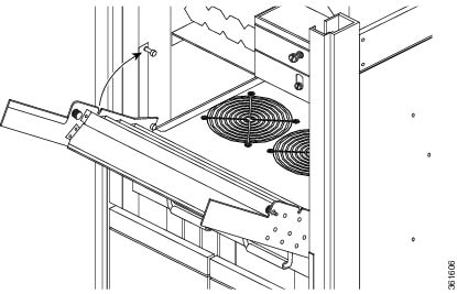
The chassis has a serviceable air filter mounted in a slide-out tray accessible from the rear of the chassis just below the lower card cage. The air filter removes dust from the room air drawn into the router by the two fan trays. Once a month (or more often in dusty environments) you should examine the air filter and replace it if it appears damaged or excessively dirty.
How to Replace Air Circulation Components
This section contains the following procedures:
Replacing a Fan Tray
This section describes how to replace a fan tray in the Cisco CRS Series Enhanced 16-Slot Line Card Chassis. For information on the fan tray, see the Information About the Air Circulation Components . For complete information on regulatory compliance and safety, see Regulatory Compliance and Safety Information for the Cisco CRS Carrier Routing System .
Prerequisites
Before performing this task, you must first open the chassis doors on the rear (MSC) side of the chassis, if installed. If you are replacing the upper fan tray, you must remove the upper grille from the rear (MSC) side of the chassis. If you are replacing the lower fan tray, you must remove the rear kick plate from the rear (MSC) side of the chassis.
Required Tools and Equipment
You need the following tools and part to perform this task:
- ESD-preventive wrist strap
- 6-in. long number 1 Phillips screwdriver
- Fan tray—Cisco product number CRS-16-FANTRAY=
Steps
To replace a fan tray, perform the following steps:
1. Attach the ESD-preventive wrist strap to your wrist and connect its leash to one of the ESD connection sockets: on the front (PLIM) side of the chassis there is one ESD connection socket right above the fan controllers. On the rear (MSC) side of the chassis there are two ESD connection sockets right above the cable management tray in the center of the chassis (left and right). You can also connect the ESD-preventive wrist strap leash to any bare metal surface on the chassis.
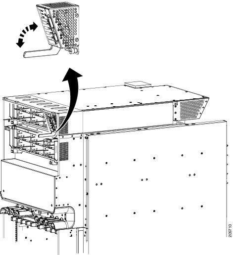
2. Using the screwdriver, loosen the two captive screws on the fan tray faceplate. If necessary, use a step platform to reach the upper fan tray comfortably.
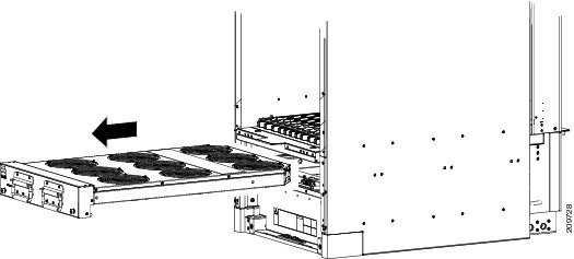
3. Pull firmly on the two handles to pull it free; two people are required to remove the fan tray.
4. Grasp the fan tray handles and pull it straight out to disconnect the fan tray from the connector mounted on the front of the fan tray bay on the rear (MSC) side of the chassis. Slide the fan tray halfway from the fan tray bay.
5. Use your free hands to support the fan tray, then slide the fan tray completely from the fan tray bay.
6. Set the fan tray carefully aside.
7. To install the replacement fan tray using two hands to support it, position the fan tray in front of the fan tray bay (label is on top).
8. Slide the fan tray into the fan tray bay. Stop when the fan tray makes contact with the chassis connector in the back of the fan tray bay.
9. Firmly push on the fan tray handles to seat the fan tray connector in the chassis connector. When completely seated, the fan tray faceplate flanges meet the rear (MSC) side of the chassis.
10. Tighten the two captive screws on the fan tray faceplate.
DETAILED STEPS
| Step 1 | Attach the ESD-preventive wrist strap to your wrist and connect its leash to one of the ESD connection sockets: on the front (PLIM) side of the chassis there is one ESD connection socket right above the fan controllers. On the rear (MSC) side of the chassis there are two ESD connection sockets right above the cable management tray in the center of the chassis (left and right). You can also connect the ESD-preventive wrist strap leash to any bare metal surface on the chassis. | ||
| Step 2 |
Using the screwdriver, loosen the two captive screws on the fan tray faceplate. If necessary, use a step platform to reach the upper fan tray comfortably.
 | ||
| Step 3 |
Pull firmly on the two handles to pull it free; two people are required to remove the fan tray.
| ||
| Step 4 | Grasp the fan tray handles and pull it straight out to disconnect the fan tray from the connector mounted on the front of the fan tray bay on the rear (MSC) side of the chassis. Slide the fan tray halfway from the fan tray bay. | ||
| Step 5 | Use your free hands to support the fan tray, then slide the fan tray completely from the fan tray bay. | ||
| Step 6 | Set the fan tray carefully aside. | ||
| Step 7 |
To install the replacement fan tray using two hands to support it, position the fan tray in front of the fan tray bay (label is on top).
| ||
| Step 8 |
Slide the fan tray into the fan tray bay. Stop when the fan tray makes contact with the chassis connector in the back of the fan tray bay.
| ||
| Step 9 |
Firmly push on the fan tray handles to seat the fan tray connector in the chassis connector. When completely seated, the fan tray faceplate flanges meet
the rear (MSC) side
of the chassis.
| ||
| Step 10 | Tighten the two captive screws on the fan tray faceplate. |
What to Do Next
After performing this task, close the doors (if installed) and re-install the upper grille or rear kick plate on the rear (MSC) side of the chassis, as necessary. For more information, see the Installing the Rear (MSC) Side Cosmetic Components.
Replacing the Air Filter
This section describes how to replace the air filter in the Cisco CRS Series Enhanced 16-Slot Line Card Chassis. For further information, see the Information About the Air Circulation Components. For complete information on regulatory compliance and safety, see Regulatory Compliance and Safety Information for the Cisco CRS Carrier Routing System .
Note | A lattice of wire exists on both sides of the filter material with an arrow denoting airflow direction and a pair of sheet metal straps on the downstream side of the filter assembly. |
Prerequisites
Before performing this task, you must first open the doors and remove the lower grille on the Rear (MSC) side of the chassis. See the Removing the Rear (MSC) Side Cosmetic Components for more information.
Caution | Never operate the Cisco CRS Series Enhanced 16-Slot Line Card Chassis without an air filter. Operating a Cisco CRS Series Enhanced 16-Slot Line Card Chassis without a filter or leaving an air filter cover off for an extended time can result in damage to the hardware. |
Required Tools and Equipment
You need the following tools and part to perform this task:
- ESD-preventive wrist strap
- 6-in. long number 1 Phillips screwdriver
- Air filter—Cisco product number CRS-16-FILTER=
Steps
To replace the air filter, perform the following steps:
1. Attach the ESD-preventive wrist strap to your wrist and connect its leash to one of the ESD connection sockets on the front (PLIM) side of the chassis or a bare metal surface on the chassis.
2. Using the screwdriver, loosen the two captive screws on the filter cover faceplate. Pull firmly on the cover to swing it free; some force may be required.
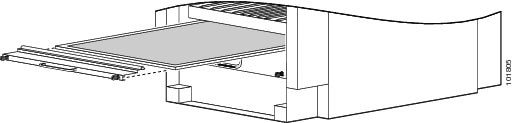
3. Insert the new air filter on top of the existing (old) air filter and push the new air filter into the air filter slot until it is seated fully within the slot.
4. Grasp the tabs at the front of the existing (old) air filter beneath the new air filter and carefully slide it from the slot.
5. Set this old air filter carefully aside.
6. Replace the filter cover and tighten the two captive screws on the front.
DETAILED STEPS
| Step 1 | Attach the ESD-preventive wrist strap to your wrist and connect its leash to one of the ESD connection sockets on the front (PLIM) side of the chassis or a bare metal surface on the chassis. |
| Step 2 | Using the screwdriver, loosen the two captive screws on the filter cover faceplate. Pull firmly on the cover to swing it free; some force may be required. |
| Step 3 | Insert the new air filter on top of the existing (old) air filter and push the new air filter into the air filter slot until it is seated fully within the slot. |
| Step 4 | Grasp the tabs at the front of the existing (old) air filter beneath the new air filter and carefully slide it from the slot. |
| Step 5 | Set this old air filter carefully aside. |
| Step 6 | Replace the filter cover and tighten the two captive screws on the front. |
What to Do Next
After performing this task, re-install the lower grille and close the doors on the Rear (MSC) side of the chassis. For more information, see the Removing the Rear (MSC) Side Cosmetic Components.
Removing Power Components
This section describes how to remove power components from the Cisco CRS enhanced 16-slot line card chassis.
Note | Although there are differences between the different types of power shelves and PMs (AC and DC), they are installed and removed using the same procedures. |
While it is possible to remove power components from the Cisco CRS enhanced 16-slot line card chassis separately, some parts (such as the power shelf) require that other parts be removed first.
We recommend that you remove the power components in the order outlined in this section. This section contains the following procedures:
- Removing a Power Module Slot Cover
- Removing a Power Module
- Removing an Alarm Module
- Removing the Exhaust Air Deflector
- Removing AC or DC Power Shelf Wiring
- Removing a Power Shelf
- Removing the Upper Grille Support
- Removing the Chassis Ground Cable
- Disconnecting the Power A Bus Bar
Removing a Power Module Slot Cover
This section describes how to remove a PM slot cover from a PM slot in an AC or DC power shelf. For complete information on regulatory compliance and safety, see Regulatory Compliance and Safety Information for the Cisco CRS Carrier Routing System .
Prerequisites
Before performing this task, you must first remove the upper grille on the front (SFC) side of the chassis, if installed. See the Removing the Upper Grille Support.
Required Tools and Equipment
You need the following tools to perform this task:
- ESD-preventive wrist strap
Steps
To remove a PM slot cover from a power shelf, perform the following steps:
1. Attach the ESD-preventive wrist strap to your wrist and connect its leash to one of the ESD connection sockets: on the front (PLIM) side of the chassis there is one ESD connection socket right above the fan controllers. On the rear (MSC) side of the chassis there are two ESD connection sockets right above the cable management tray in the center of the chassis (left and right). You can also connect the ESD-preventive wrist strap leash to any bare metal surface on the chassis.
2. Gently pinch the tab on the left side of the PM slot cover to detach the PM slot cover from the PM slot.
3. Remove the two tabs on the right side of the PM slot cover from the two holes on the right side of the PM slot.
4. Set the PM slot cover aside.
DETAILED STEPS
| Step 1 | Attach the ESD-preventive wrist strap to your wrist and connect its leash to one of the ESD connection sockets: on the front (PLIM) side of the chassis there is one ESD connection socket right above the fan controllers. On the rear (MSC) side of the chassis there are two ESD connection sockets right above the cable management tray in the center of the chassis (left and right). You can also connect the ESD-preventive wrist strap leash to any bare metal surface on the chassis. |
| Step 2 | Gently pinch the tab on the left side of the PM slot cover to detach the PM slot cover from the PM slot. |
| Step 3 | Remove the two tabs on the right side of the PM slot cover from the two holes on the right side of the PM slot. |
| Step 4 |
Set the PM slot cover aside.
 |
What to Do Next
After performing this task, install an AC or DC PM, if necessary. For more information, see Installing a Power Module. Re-install the upper grille on the front (SFC) side of the chassis. If you plan to remove the power shelf completely, you must first remove all of the PM slot covers, PMs, and the alarm module from the power shelf. See the Removing a Power Module and the Removing an Alarm Module for more information.
Removing a Power Module
This section describes how to remove a PM from a power shelf. For complete information on regulatory compliance and safety, see Regulatory Compliance and Safety Information for the Cisco CRS Carrier Routing System .
Prerequisites
Before performing this task, you must first remove the upper grille on the front (PLIM) side of the chassis, if installed.
Required Tools and Equipment
You need the following tools to perform this task:
- ESD-preventive wrist strap
- 6-in. long number 1 Phillips screwdriver
Steps
To remove a PM from a power shelf, perform the following steps:
1. Attach the ESD-preventive wrist strap to your wrist and connect its leash to one of the ESD connection sockets: on the front (PLIM) side of the chassis there is one ESD connection socket right above the fan controllers. On the rear (MSC) side of the chassis there are two ESD connection sockets right above the cable management tray in the center of the chassis (left and right). You can also connect the ESD-preventive wrist strap leash to any bare metal surface on the chassis.
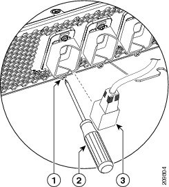
2. Using the screwdriver, unscrew the ejector from the PM.
3. Flip down the ejector. Slide the PM out of the power shelf, and carefully place it down on a flat surface.
DETAILED STEPS
| Step 1 | Attach the ESD-preventive wrist strap to your wrist and connect its leash to one of the ESD connection sockets: on the front (PLIM) side of the chassis there is one ESD connection socket right above the fan controllers. On the rear (MSC) side of the chassis there are two ESD connection sockets right above the cable management tray in the center of the chassis (left and right). You can also connect the ESD-preventive wrist strap leash to any bare metal surface on the chassis. |
| Step 2 | Using the screwdriver, unscrew the ejector from the PM.
 |
| Step 3 | Flip down the ejector. Slide the PM out of the power shelf, and carefully place it down on a flat surface. |
What to Do Next
After performing this task, install a replacement AC or DC PM, if necessary (see Installing a Power Module) and re-install the upper grille on the front (SFC) side of the chassis. If you plan to remove the power shelf completely, you must first remove all of the power modules and the alarm module from the power shelf (see Removing an Alarm Module).
Removing an Alarm Module
This section describes how to remove an alarm module from a power shelf installed in the Cisco CRS enhanced 16-slot line card chassis. For complete information on regulatory compliance and safety, see Regulatory Compliance and Safety Information for the Cisco CRS Carrier Routing System .
Prerequisites
Before performing this task, you must first remove the upper grille on the front (SFC) side of the chassis, if installed. See Removing the Front (PLIM) Side Cosmetic Components.
Required Tools and Equipment
You need the following tools to perform this task:
- ESD-preventive wrist strap
- 6-in. long number 1 Phillips screwdriver
Steps
To remove the alarm module, perform the following steps:
1. Attach the ESD-preventive wrist strap to your wrist and connect its leash to one of the ESD connection sockets: on the front (PLIM) side of the chassis there is one ESD connection socket right above the fan controllers. On the rear (MSC) side of the chassis there are two ESD connection sockets right above the cable management tray in the center of the chassis (left and right). You can also connect the ESD-preventive wrist strap leash to any bare metal surface on the chassis.
2. Use the screwdriver to loosen the captive screw securing the alarm module to the power shelf on the lower right corner of the alarm module.
3. Rotate the alarm module ejector lever downwards to eject the alarm module from the power shelf.
4. Slide the alarm module out of the power shelf, and carefully place it down on a flat surface.
DETAILED STEPS
| Step 1 | Attach the ESD-preventive wrist strap to your wrist and connect its leash to one of the ESD connection sockets: on the front (PLIM) side of the chassis there is one ESD connection socket right above the fan controllers. On the rear (MSC) side of the chassis there are two ESD connection sockets right above the cable management tray in the center of the chassis (left and right). You can also connect the ESD-preventive wrist strap leash to any bare metal surface on the chassis. |
| Step 2 | Use the screwdriver to loosen the captive screw securing the alarm module to the power shelf on the lower right corner of the alarm module. |
| Step 3 |
Rotate the alarm module ejector lever downwards to eject the alarm module from the power shelf.
 |
| Step 4 | Slide the alarm module out of the power shelf, and carefully place it down on a flat surface. |
What to Do Next
After performing this task, install a replacement alarm module, if necessary, (see Installing an Alarm Module) and re-install the upper grille on the front (SFC) side of the chassis. If you plan to remove the power shelf completely, remove the AC or DC wiring from the rear of the power shelf (see Removing AC or DC Power Shelf Wiring). If you plan to remove wiring from the lower power shelf, you will need to remove the exhaust air deflector first (see Removing the Exhaust Air Deflector).
Removing the Exhaust Air Deflector
This section describes how to remove the exhaust air deflector from the rear of the Cisco CRS enhanced 16-slot line card chassis. For complete information on regulatory compliance and safety, see Regulatory Compliance and Safety Information for the Cisco CRS Carrier Routing System .
The exhaust air deflector must be removed before installing the lower power shelf.
Prerequisites
There are no prerequisites for this task.
Required Tools and Equipment
You need the following tools and equipment to perform this task:
- 6-in. long number 2 Phillips screwdriver
Steps
1. Unscrew the captive screw on both sides.
2. Rotate the air deflector backward until seated on the lower standoff.
3. Lift the air deflector off of the lower standoff.
DETAILED STEPS
What to Do Next
After the exhaust air deflector has been removed from the rear of the chassis, remove the AC or DC wiring from the rear of the power shelf. Continue to Installing an AC or DC Power Shelf for instructions.
Removing AC or DC Power Shelf Wiring
This section describes how to remove the DC input wiring, DC terminal block covers and AC cords from the rear of the power shelf on the Cisco CRS enhanced 16-slot line card chassis. For complete information on regulatory compliance and safety, see Regulatory Compliance and Safety Information for the Cisco CRS Carrier Routing System .
- Removing DC Power Shelf Wiring
- Prerequisites
- Required Tools and Equipment
- Steps
- What To Do Next
- Removing AC Power Shelf Wiring
- Prerequisites
- Required Tools and Equipment
- Steps
- What To Do Next
Removing DC Power Shelf Wiring
This section describes how to remove the DC power shelf wiring from the rear of the DC power shelf.
For additional power shelf details, see Cisco CSR-1 Series Carrier Routing System Description or Cisco CRS 16-Slot EC Line Card Chassis Specifications.
Prerequisites
Before performing this task, power down and remove DC PMs and the alarm module in the shelf you want to disconnect. Remove the upper grille from the rear (MSC) side of the chassis, if installed. If you plan to remove power from the lower power shelf, remove the exhaust air deflector from the rear of the chassis first. See Removing the Exhaust Air Deflector.
Note | Before removing wiring from the power shelf, make sure that the input power cables are not energized. |
Required Tools and Equipment
You need the following tools to perform this task:
- ESD-preventive wrist strap
- 6-in. long number 1 Phillips screwdriver
- 3/8-in. ratchet wrench with 10-mm socket
- Volt ohm meter
Steps
To disconnect wiring from the DC power shelf, perform the following steps:
1. Attach the ESD-preventive wrist strap to your wrist and connect its leash to one of the ESD connection sockets: on the front (PLIM) side of the chassis there is one ESD connection socket right above the fan controllers. On the rear (MSC) side of the chassis there are two ESD connection sockets right above the cable management tray in the center of the chassis (left and right). You can also connect the ESD-preventive wrist strap leash to any bare metal surface on the chassis.
2. Verify that the power LEDs on the rear of the power shelf are off for all inputs on the power shelf that is being removed.
3. Using the volt ohm meter, verify that there is no voltage on the cables that are about to be removed.
4. Use the screwdriver to remove the screw that secures the terminal block cover into the mounting standoff.
5. Slide the terminal block cover downwards.
6. Remove the terminal block cover.
7. Using the 10-mm socket wrench, remove the positive and negative cable pairs from each terminal block.
8. Replace the terminal block cover.
DETAILED STEPS
| Step 1 | Attach the ESD-preventive wrist strap to your wrist and connect its leash to one of the ESD connection sockets: on the front (PLIM) side of the chassis there is one ESD connection socket right above the fan controllers. On the rear (MSC) side of the chassis there are two ESD connection sockets right above the cable management tray in the center of the chassis (left and right). You can also connect the ESD-preventive wrist strap leash to any bare metal surface on the chassis. | ||
| Step 2 | Verify that the power LEDs on the rear of the power shelf are off for all inputs on the power shelf that is being removed. | ||
| Step 3 | Using the volt ohm meter, verify that there is no voltage on the cables that are about to be removed. | ||
| Step 4 | Use the screwdriver to remove the screw that secures the terminal block cover into the mounting standoff. | ||
| Step 5 | Slide the terminal block cover downwards. | ||
| Step 6 | Remove the terminal block cover. | ||
| Step 7 |
Using the 10-mm socket wrench, remove the positive and negative cable pairs from each terminal block.
| ||
| Step 8 | Replace the terminal block cover. |
What To Do Next
After you remove the DC terminal block covers and DC wiring, you can remove the power shelf from the chassis completely. See Removing a Power Shelf.
Removing AC Power Shelf Wiring
This section describes how to remove input AC cords from the rear of the DC power shelf.
Prerequisites
Before performing this task, power down and remove AC PMs and the alarm module in the shelf you want to disconnect. Remove the upper grille from the rear (MSC) side of the chassis, if installed.
Note | Before removing wiring from the power shelf, make sure that the input power cables are not energized. |
Required Tools and Equipment
You need the following tools to perform this task:
- 6-in. long number 1 Phillips screwdriver
Steps
To remove the input AC cords, go to the rear of the chassis and perform the following steps:
1. Verify that the AC input source breaker is in the OFF position.
2. Use the screwdriver to loosen the screws that clamp the cords in place.
3. Remove the cords from the cord clamps.
DETAILED STEPS
| Step 1 | Verify that the AC input source breaker is in the OFF position. | ||||
| Step 2 | Use the screwdriver to loosen the screws that clamp the cords in place.
| ||||
| Step 3 | Remove the cords from the cord clamps. |
What To Do Next
After you remove the AC cords, you can remove the power shelf from the chassis completely. See Removing a Power Shelf.
Removing a Power Shelf
This section describes how to remove the power shelf from the Cisco CRS enhanced 16-slot line card chassis. For complete information on regulatory compliance and safety, see Regulatory Compliance and Safety Information for the Cisco CRS Carrier Routing System .
Prerequisites
Before performing this task, remove the upper grilles from the front (PLIM) and rear (MSC) sides of the chassis (if installed), the AC or DC PMs, alarm module, and the AC or DC input power wiring from the shelf that you want to disconnect. For more information, see the Removing a Power Module, the Removing an Alarm Module , and the Removing AC or DC Power Shelf Wiring .
Required Tools and Equipment
You need the following tools to perform this task:
- 6 in. long number 2 Phillips screwdriver
Caution | Do not use the handles for lifting or supporting the power shelf, because this could severely damage the handles. |
Caution | Do not bend the handles sideways during any part of the removal process. |
Steps
To remove a power shelf, perform the following steps:
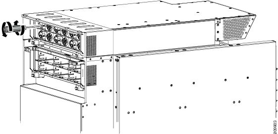
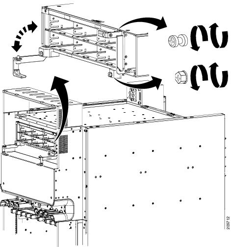
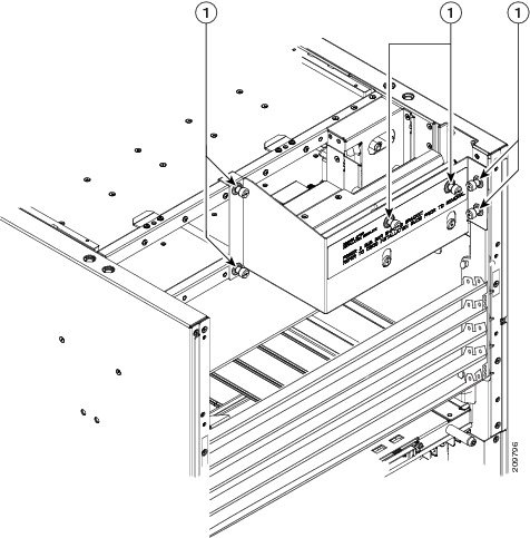
1. Using the screwdriver, remove the screws that secure the bottom of the power shelves to the chassis. There is one screw on each side of the power shelf.
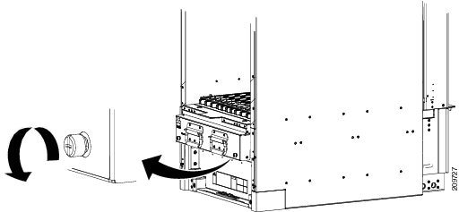
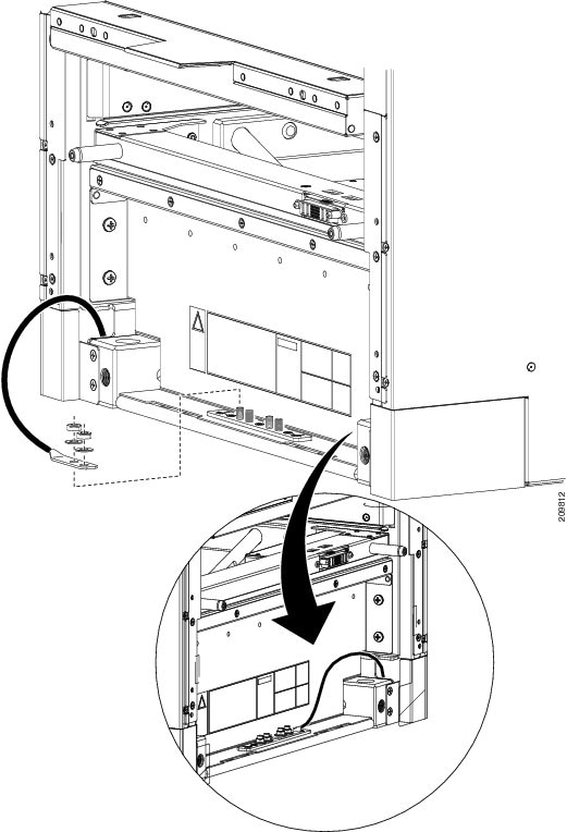
2. Using the screwdriver, loosen the captive screws on the power shelf handles on the power shelf. Each power shelf handle contains one captive screw. The handles will fall down away from the shelf, as shown in the following image.
3. Grasping both handles simultaneously, pull both the left and right handles down and out at the same time to pull the shelf partially out of the chassis.
4. When the shelf is partially out of the chassis and the ejector handles are away from the pins, rotate the handles back up to the closed position and hand-tighten the handle screws back into the shelf.
5. Using two people, one to support the power shelf underneath and the other to keep it steady, slide the shelf out of the chassis, and carefully set it down on a flat surface.
6. Remove the second power shelf, if necessary, by following step 1 through step 5.
DETAILED STEPS
| Step 1 | Using the screwdriver, remove the screws that secure the bottom of the power shelves to the chassis. There is one screw on each side of the power shelf.
| ||
| Step 2 | Using the screwdriver, loosen the captive screws on the power shelf handles on the power shelf. Each power shelf handle contains one captive screw. The handles will fall down away from the shelf, as shown in the following image.
 | ||
| Step 3 | Grasping both handles simultaneously, pull both the left and right handles down and out at the same time to pull the shelf partially out of the chassis. | ||
| Step 4 | When the shelf is partially out of the chassis and the ejector handles are away from the pins, rotate the handles back up to the closed position and hand-tighten the handle screws back into the shelf. | ||
| Step 5 |
Using two people, one to support the power shelf underneath and the other to keep it steady, slide the shelf out of the chassis, and carefully set it down on a flat surface.
| ||
| Step 6 | Remove the second power shelf, if necessary, by following step 1 through step 5. |
What to Do Next
After performing this task, install a replacement power shelf, if necessary, (see the Installing an AC or DC Power Shelf), and replace the upper grille on the front (PLIM) and rear (MSC) sides of the chassis.
Removing the Upper Grille Support
This section describes how to remove the upper grille support from the Cisco CRS enhanced 16-slot line card chassis. For complete information on regulatory compliance and safety, see Regulatory Compliance and Safety Information for the Cisco CRS Carrier Routing System .
Prerequisites
Before performing this task, remove the upper grilles from the front (PLIM) and rear (MSC) sides of the chassis (if installed), the AC or DC PMs, alarm module, and the AC or DC input power wiring, and the power shelves from the chassis. For more information, see the following sections:
Required Tools and Equipment
You need the following tool to perform this task:
- 6-in. long number 1 Phillips screwdriver
Steps
To remove the upper grille support from the chassis, perform the following steps:
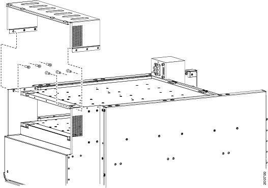
1. Use the screwdriver to remove the six M4 flat head screws, three on each side, that attach the upper grille support to the chassis.
2. Remove the upper grille support from the front of the chassis, and set it aside.
DETAILED STEPS
Removing the Chassis Ground Cable
This section describes how to remove the chassis ground cable on the Cisco CRS enhanced 16-slot line card chassis. For complete information on regulatory compliance and safety, see Regulatory Compliance and Safety Information for the Cisco CRS Carrier Routing System .
Prerequisites
Before performing this task, remove the AC or DC input power wiring from both power shelves, and remove both power shelves from the chassis.
Caution | Do not remove the chassis ground cable unless the chassis is being replaced. |
Required Tools and Equipment
You need the following tools and equipment to perform this task:
- 3/8 in. drive socket wrench
- 10-mm 6 pt. socket wrench
Steps
To remove the ground cable from the chassis, perform the following steps:
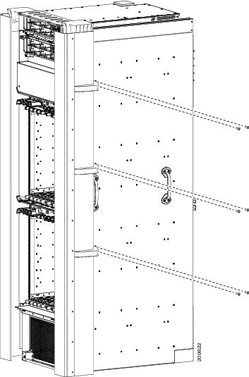
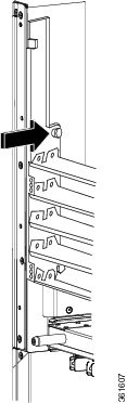
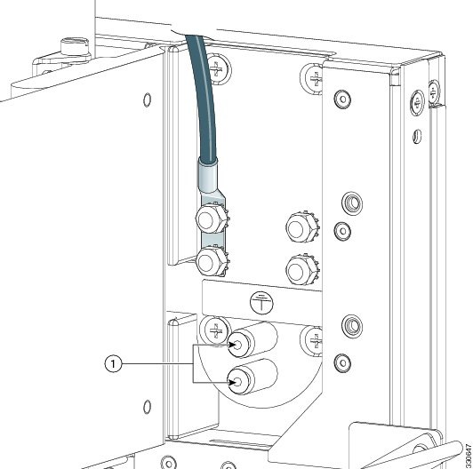
1. If the ground cable is connected to the grounding point at the top of the chassis, use the 10-mm wrench to remove the two M6 bolts that attach the ground cable to the grounding point, as shown in the following image.
2. If the ground cable is connected to the grounding point at the bottom of the chassis, use the 10-mm wrench to remove the two M6 nuts that secure the ground cable to the grounding point.
DETAILED STEPS
| Step 1 | If the ground cable is connected to the grounding point at the top of the chassis, use the 10-mm wrench to remove the two M6 bolts that attach the ground cable to the grounding point, as shown in the following image.
| ||
| Step 2 | If the ground cable is connected to the grounding point at the bottom of the chassis, use the 10-mm wrench to remove the two M6 nuts that secure the ground cable to the grounding point.
 |
Disconnecting the Power A Bus Bar
This section describes how to disconnect the Power A bus bar from the rear of the Cisco CRS enhanced 16-slot line card chassis.
Prerequisites
Before performing this task, remove all power components, including alarm modules, power modules, DC wiring or AC cables, and both power shelves from the chassis.
Required Tools and Equipment
You need the following tool to perform this task:
- 6-in. long number 1 Phillips screwdriver
- Power A bus bar shipping bracket
Steps
To disconnect the Power A bus bar, perform the following steps:
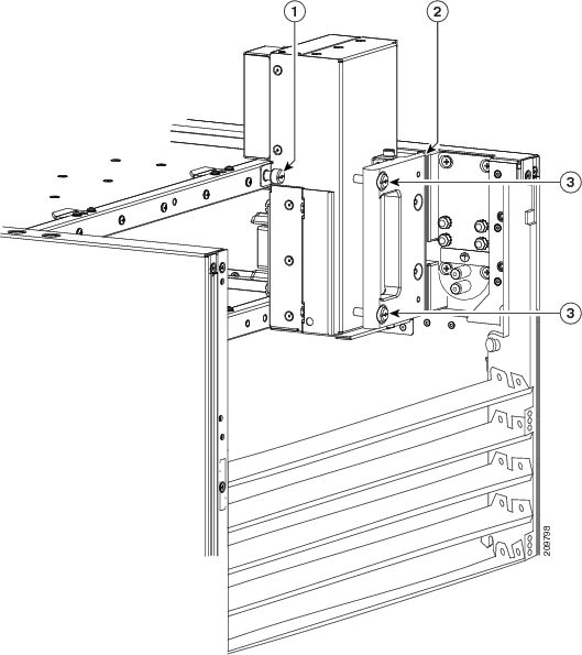
1. Loosen the Phillips captive screw that secures the Power A bus bar to the chassis. The screw is located on the tab on the left side of the power bus bar.
2. Loosen the two captive screws on the Power A bus bar handle.
3. Remove the Power A bus bar from where it is seated.
4. Carefully secure the Power A bus bar to the chassis frame in a horizontal position by re-installing the shipping bracket. Tighten the six captive screws that attach the shipping bracket to the rear of the chassis.
DETAILED STEPS
| Step 1 | Loosen the Phillips captive screw that secures the Power A bus bar to the chassis. The screw is located on the tab on the left side of the power bus bar.
| ||||||
| Step 2 | Loosen the two captive screws on the Power A bus bar handle. | ||||||
| Step 3 |
Remove the Power A bus bar from where it is seated.
| ||||||
| Step 4 | Carefully secure the Power A bus bar to the chassis frame in a horizontal position by re-installing the shipping bracket. Tighten the six captive screws that attach the shipping bracket to the rear of the chassis.
|
Converting from One Power System to the Other
This section describes how to convert from one power system to another (either from AC to DC, or from DC to AC). For complete information on regulatory compliance and safety, see Regulatory Compliance and Safety Information for the Cisco CRS Carrier Routing System .
Steps
To convert a Cisco CRS Series Enhanced 16-slot Line Card Chassis with a power system from AC to DC power, or from DC to AC power, perform the following steps:
1. Power down the chassis completely. See Power Down a Chassis
2. Remove the AC or DC PMs. See Removing a Power Module.
3. Remove the alarm modules. See Removing an Alarm Module.
4. Unplug the AC power cords or remove the DC fusing from the power source. Remove the AC or DC wiring from the rear of the power shelf. See Removing AC or DC Power Shelf Wiring.
5. Remove the power shelves. See Removing a Power Shelf.
6. Install the new power shelves. See Installing an AC or DC Power Shelf.
7. Install the power shelf wiring. See Installing AC or DC Power Shelf Wiring .
8. Install the alarm modules. See Installing an Alarm Module.
9. Install the AC or DC PMs. See Installing a Power Module.
10. Power the chassis back up. See Power Up and Power Down a Chassis .
DETAILED STEPS
| Step 1 | Power down the chassis completely. See Power Down a Chassis | ||
| Step 2 | Remove the AC or DC PMs. See Removing a Power Module. | ||
| Step 3 | Remove the alarm modules. See Removing an Alarm Module. | ||
| Step 4 | Unplug the AC power cords or remove the DC fusing from the power source. Remove the AC or DC wiring from the rear of the power shelf. See Removing AC or DC Power Shelf Wiring. | ||
| Step 5 | Remove the power shelves. See Removing a Power Shelf. | ||
| Step 6 | Install the new power shelves. See Installing an AC or DC Power Shelf. | ||
| Step 7 | Install the power shelf wiring. See Installing AC or DC Power Shelf Wiring .
| ||
| Step 8 | Install the alarm modules. See Installing an Alarm Module. | ||
| Step 9 | Install the AC or DC PMs. See Installing a Power Module. | ||
| Step 10 | Power the chassis back up. See Power Up and Power Down a Chassis . |
What to Do Next
Note | Use only one type of power shelf—AC or DC—and its mating AC or DC PM in a chassis at one time. |
What to Do Next
Be sure that all parts have been carefully set aside and repackaged appropriately.
 Feedback