- Preface
- Installation Roadmap Overview
- Cisco CRS 16-Slot Line Card Chassis Enhanced Router
- Installing Power Components
- Installing and Removing Air Circulation Components
- Installing Exterior Cosmetic Components
- Installing Line Cards, PLIMs, and Associated Components
- Removing Chassis Components
- Upgrading Chassis Components
- Cisco CRS 16-Slot EC Line Card Chassis Specifications
- Product IDs
Installing and Removing Air Circulation Components
This chapter provides instructions on how to install and replace the Cisco CRS Series Enhanced 16-Slot Line Card Chassis air circulation components.
 Note | The chassis is shipped with the fan trays and air filter pre-installed. |
This chapter presents the following topics:
Information About the Air Circulation Components
This section contains some general information about the air circulation components in the following topics:
About the Fan Trays
The Cisco CRS Series Enhanced 16-Slot Line Card Chassis has two fan trays (see Figure 1), one just below the lower card cage and the other just above the upper card cage. The chassis can run with only one fan tray operating. If a failure occurs in one fan tray, the other fan tray acts as the redundant fan tray to assure fault-tolerant system performance; the chassis continues to operate while the failed fan tray is replaced.
The Cisco CRS Series Enhanced 16-Slot Line Card Chassis fan tray operates in either the upper or lower fan tray slots. Each fan tray installs into the rear (MSC) side of the chassis and contains:
- Nine fans
- Fan tray board
- Front-panel status LED
Note | The upper and lower fan trays are interchangeable and installed in the same manner. |

|
1 |
Front (PLIM) side of chassis |
6 |
Power shelves (two installed) |
|
2 |
Air intake |
7 |
Air exhaust |
|
3 |
Lower fan tray |
8 |
Upper card cage |
|
4 |
Air filter |
9 |
Lower card cage |
|
5 |
Upper fan tray |
10 |
Rear [MSC] side of chassis |
About the Air Filter
The chassis has a serviceable air filter mounted in a slide-out tray accessible from the rear of the chassis just below the lower card cage (see Figure 1). The air filter removes dust from the room air drawn into the router by the two fan trays. Once a month (or more often in dusty environments) you should examine the air filter and replace it if it appears damaged or excessively dirty.
 Caution | Periodic maintenance of the air filter is required to maintain proper air flow in the system as well as to avoid optical contamination. It is highly recommended to clean air filters once in three months and also replace the air filter once in a year. |
How to Replace Air Circulation Components
This section contains the following procedures:
Replacing a Fan Tray
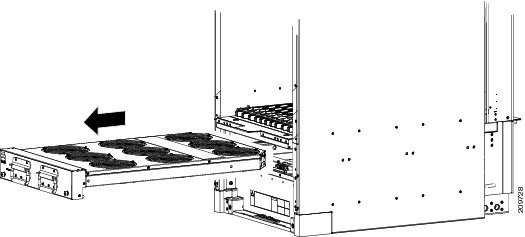
This section describes how to replace a fan tray (see Fan Tray figure below) in the Cisco CRS Series Enhanced 16-Slot Line Card Chassis. For information on the fan tray, see the Information About the Air Circulation Components. For complete information on regulatory compliance and safety, see Regulatory Compliance and Safety Information for the Cisco CRS Carrier Routing System .
Prerequisites
Before performing this task, you must first open the chassis doors on the rear (MSC) side of the chassis, if installed. If you are replacing the upper fan tray, you must remove the upper grille from the rear (MSC) side of the chassis. If you are replacing the lower fan tray, you must remove the lower chassis cosmetic bezel from the rear (MSC) side of the chassis.
Required Tools and Equipment
You need the following tools and part to perform this task:
- ESD-preventive wrist strap
- 6-in. long number 1 Phillips screwdriver
- Fan tray—Cisco product number CRS-16-FANTRAY
Steps
To replace a fan tray, follow these steps:
1. Attach the ESD-preventive wrist strap to your wrist and connect its leash to one of the ESD connection sockets: on the front (PLIM) side of the chassis there is one ESD connection socket right above the fan controllers. On the rear (MSC) side of the chassis there are two ESD connection sockets right above the cable management tray in the center of the chassis (left and right). You can also connect the ESD-preventive wrist strap leash to any bare metal surface on the chassis.
2. Using the screwdriver, loosen the two captive screws on the fan tray faceplate. If necessary, use a step platform to reach the upper fan tray comfortably.
3. Pull firmly on the two handles to pull it free; two people are required to remove the fan tray.
4. Grasp the fan tray handles and pull it straight out to disconnect the fan tray from the connector mounted on the front of the fan tray bay on the rear (MSC) side of the chassis. Slide the fan tray halfway from the fan tray bay.
5. Use your free hands to support the fan tray, then slide the fan tray completely from the fan tray bay.
6. Set the fan tray carefully aside.
7. To install the replacement fan tray using two hands to support it, position the fan tray in front of the fan tray bay (label is on top).
8. Slide the fan tray into the fan tray bay. Stop when the fan tray makes contact with the chassis connector in the back of the fan tray bay.
9. Firmly push on the fan tray handles to seat the fan tray connector in the chassis connector. When completely seated, the fan tray faceplate flanges meet the rear (MSC) side of the chassis.
10. Tighten the two captive screws on the fan tray faceplate.
DETAILED STEPS
| Step 1 | Attach the ESD-preventive wrist strap to your wrist and connect its leash to one of the ESD connection sockets: on the front (PLIM) side of the chassis there is one ESD connection socket right above the fan controllers. On the rear (MSC) side of the chassis there are two ESD connection sockets right above the cable management tray in the center of the chassis (left and right). You can also connect the ESD-preventive wrist strap leash to any bare metal surface on the chassis. | ||
| Step 2 |
Using the screwdriver, loosen the two captive screws on the fan tray faceplate. If necessary, use a step platform to reach the upper fan tray comfortably.
| ||
| Step 3 |
Pull firmly on the two handles to pull it free; two people are required to remove the fan tray.
| ||
| Step 4 | Grasp the fan tray handles and pull it straight out to disconnect the fan tray from the connector mounted on the front of the fan tray bay on the rear (MSC) side of the chassis. Slide the fan tray halfway from the fan tray bay. | ||
| Step 5 | Use your free hands to support the fan tray, then slide the fan tray completely from the fan tray bay. | ||
| Step 6 | Set the fan tray carefully aside. | ||
| Step 7 |
To install the replacement fan tray using two hands to support it, position the fan tray in front of the fan tray bay (label is on top).
| ||
| Step 8 |
Slide the fan tray into the fan tray bay. Stop when the fan tray makes contact with the chassis connector in the back of the fan tray bay.
| ||
| Step 9 |
Firmly push on the fan tray handles to seat the fan tray connector in the chassis connector. When completely seated, the fan tray faceplate flanges meet
the rear (MSC) side
of the chassis.
| ||
| Step 10 | Tighten the two captive screws on the fan tray faceplate. |
What to Do Next
After performing this task, close the doors (if installed) and re-install the upper grille or lower chassis cosmetic bezel on the rear (MSC) side of the chassis, as necessary. For more information, see the Installing the Rear (MSC) Side Cosmetic Components.
Replacing the Air Filter
This section describes how to replace the air filter in the Cisco CRS Series Enhanced 16-Slot Line Card Chassis. For further information, see the Information About the Air Circulation Components. For complete information on regulatory compliance and safety, see Regulatory Compliance and Safety Information for the Cisco CRS Carrier Routing System .
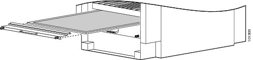
Note | A lattice of wire exists on both sides of the filter material with an arrow denoting airflow direction and a pair of sheet metal straps on the downstream side of the filter assembly. |
Prerequisites
Before performing this task, you must first open the doors and remove the lower grille on the Rear (MSC) side of the chassis. See the Removing the Rear (MSC) Side Cosmetic Components for more information.
Caution | Never operate the Cisco CRS Series Enhanced 16-Slot Line Card Chassis without an air filter. Operating a Cisco CRS Series Enhanced 16-Slot Line Card Chassis without a filter or leaving an air filter cover off for an extended time can result in damage to the hardware. |
Required Tools and Equipment
You need the following tools and part to perform this task:
- ESD-preventive wrist strap
- 6-in. long number 1 Phillips screwdriver
- Air filter—Cisco product number CRS-16-FILTER
Steps
To replace the air filter, perform the following steps:
1. Attach the ESD-preventive wrist strap to your wrist and connect its leash to one of the ESD connection sockets on the front (PLIM) side of the chassis or a bare metal surface on the chassis.
2. Using the screwdriver, loosen the two captive screws on the filter cover faceplate. Pull firmly on the cover to swing it free; some force may be required.
3. Insert the new air filter on top of the existing (old) air filter and push the new air filter into the air filter slot until it is seated fully within the slot.
4. Grasp the tabs at the front of the existing (old) air filter beneath the new air filter and carefully slide it from the slot.
5. Set this old air filter carefully aside.
6. Replace the filter cover and tighten the two captive screws on the front.
DETAILED STEPS
| Step 1 | Attach the ESD-preventive wrist strap to your wrist and connect its leash to one of the ESD connection sockets on the front (PLIM) side of the chassis or a bare metal surface on the chassis. |
| Step 2 | Using the screwdriver, loosen the two captive screws on the filter cover faceplate. Pull firmly on the cover to swing it free; some force may be required. |
| Step 3 | Insert the new air filter on top of the existing (old) air filter and push the new air filter into the air filter slot until it is seated fully within the slot. |
| Step 4 | Grasp the tabs at the front of the existing (old) air filter beneath the new air filter and carefully slide it from the slot. |
| Step 5 | Set this old air filter carefully aside. |
| Step 6 | Replace the filter cover and tighten the two captive screws on the front. |
What to Do Next
After performing this task, re-install the lower grille and close the doors on the Rear (MSC) side of the chassis. For more information, see the Installing the Rear (MSC) Side Cosmetic Components.
 Feedback