Precision Time Protocol

Precision Time Protocol

A Precision Time Protocol (PTP) is a time synchronization protocol that

  • achieves nanosecond-level synchronization of real-time clocks across networked devices

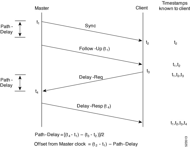
  • uses a master-client hierarchy to organize clock relationships, and

  • enables all devices in the network to continually synchronize to the most accurate clock through ongoing exchanges of timing messages.

PTP is defined in the IEEE 1588 standard. The network selects the best available clock, known as the grandmaster clock, as the authoritative time source. All other network clocks, known as members, synchronize with this grandmaster clock. The protocol identifies the port connected to the most accurate device (the master clock), then synchronizes all other devices to it and maintains synchronization throughout the network.

Restrictions for PTP

Consider these restrictions when enabling PTP on Cisco 8000 series routers.

  • Do not configure PTP over IP on tagged interfaces of the 88-LC1-52Y8H-EM and 88-LC1-12TH24FH-E line cards.

  • The Sync2 interface is supported only when the 10 megahertz (MHz), one pulse per second (PPS), and time-of-day (ToD) ports are configured.

  • Configure PTP only on interfaces without global MACSec or MACSec enabled.

  • Enable PTP only when global MACSec-FIPS-Post is not configured, since MACSec-FIPS-Post is unavailable for individual interfaces.

  • Do not configure transparent Clock. Use one-step clock mode.

  • Configure the device to receive follow-up PTP packets to support a two-step peer primary. The device does not send follow-up PTP packets.

  • Avoid configuring PTP on bundle ethernet interfaces, bundle ethernet subinterfaces, loopback interfaces, and LAG ethernet subinterfaces.

  • Configure PTP only on individual bundle member links; do not configure it on bundle-ether interfaces.

Benefits of PTP

Use PTP to achieve accurate and stable timing in smart grid power automation applications, such as peak-hour billing, virtual power generators, and outage management. Accurate timing helps you monitor networks and troubleshoot issues more effectively. You can implement PTP, a message-based protocol, on packet-based networks such as ethernet.

PTP offers these benefits for your Ethernet network:

  • It has low cost and is easy to set up in existing Ethernet networks.

  • It requires minimal bandwidth for PTP data packets.

  • It is compatible with routers and different types of network delays.

Guidelines for PTP

The guidelines for PTP on Cisco 8000 Series routers are:

  • PTP is supported on Gigabit Ethernet interfaces (1G, 10G, 40G, and 100G).

  • If you use encapsulation default or untag on a subinterface, configure PTP on the subinterface—not on the main interface.

Router delays in time synchronization

A router delay is a network timing phenomenon that

  • introduces latency in the transmission of PTP packets

  • causes packet buffering and processing delays, and

  • can be mitigated through optimized PTP configurations.

PTP clock types and roles

The Precision Time Protocol (PTP) network synchronizes clocks across devices by assigning specialized roles to each participating device. The main PTP clock types and their functions are:

  • Grandmaster (GM)—The network device connected to the primary time source. All other clocks synchronize to the grandmaster clock.

  • Ordinary Clock (OC)— A clock with one PTP port that operates in either:

    • Master mode: Distributes timing information to client clocks

    • Slave mode: Synchronizes its clock to a master clock. Slave mode can be enabled on up to two interfaces to connect to different masters

  • Boundary Clock (BC)—Selects the best master clock to synchronize with. Acts as master if no better clock is found. Starts PTP sessions with downstream client clocks, reducing network hops and packet delay between the grandmaster and clients.

  • Transparent Clock (TC)—A switch or device that measures and adds the time it takes PTP packets to transit the device to the time correction field, ensuring accurate synchronization by compensating for switch forwarding delays.


Note


  • A PTP network may include both PTP-enabled and non-PTP devices. Only devices supporting PTP can act in the roles described above.

  • Accurate placement of boundary and transparent clocks in the network improves timing precision and minimizes synchronization errors.


Port state machine

This method identifies the state of each network port. A port can be passive (neither master nor client), operate as a master that provides time to other clocks, or function as a secondary that receives time from other clocks in the network.

Best master clock algorithm

A best master clock algorithm (BMCA) is a protocol mechanism that

  • operates automatically in IEEE 1588-based PTP networks

  • compares properties of all participating clocks to decide which one will be the Grandmaster Clock, and

  • ensures a single clock distributes time to all other clocks in the network.

Frequency and time selection

The selection of the source to synchronize the device clock frequency is made by frequency synchronization which is described in the Source and Selection Points section of the Frequency Synchronization module in this document. The Announce, Sync, and Delay-request frequencies must be the same on the master and client.

Delay request-response mechanism

A Delay Request-Response mechanism is a time synchronization method defined in IEEE Std 1588-2008 that

  • enables a client port to estimate the difference between its clock and the master clock

  • supports one-step and two-step message timestamping options, and

  • is configurable for use in network devices operating in a client role.

This mechanism is a foundational element in PTP operations, helping to achieve network-wide time alignment.

Supported delay request-response options

The supported options for the delay request-response mechanism include:

  • One-step mechanism: The Sync message contains the timestamp within the Sync message itself.

  • Two-step mechanism: The timestamp for a Sync message is sent separately in a Follow-up message after the initial Sync message.

A router port operating in Client state with delay request-response enabled supports these operations:

  • Sending Delay-request messages to request timing information from the master,

  • Handling incoming Sync, Follow-up, and Delay-response messages for time synchronization.

The timeout periods for both Sync and Delay-response messages in the delay request-response mechanism are independently configurable, enabling administrators to tune synchronization behavior according to network requirements.

Role of transparent clocks in PTP

Transparent clocks are network devices that

  • measure and record the time it takes for PTP timing packets to pass through themselves,

  • insert this delay into a special time-interval field in the packets, and

  • forward all timing messages between network nodes without altering their content.

In PTP, transparent clocks make routers invisible to the master and client nodes regarding timing accuracy. By accounting for the delays they introduce, transparent clocks enable the end devices to better calculate the exact communication path delay. An end-to-end transparent clock handles all messages as a router would, with the added benefit of precise delay measurement.

Comparison of transparent clocks and regular routers

This table highlights the differences between transparent clocks and regular routers in the context of PTP:

Table 1. Difference between transparent clocks and regular routers

Attribute

Transparent clock

Regular router

Delay measurement

Measures and inserts its own delay into packets

Does not measure or account for delay

Handling of PTP messages

Forwards messages, records transit times

Simply forwards, no timestamping

Effect on synchronization

Improves time accuracy across the network

Can introduce timing inaccuracies

Network transparency in PTP

Makes itself transparent to timing calculation

Opaque; contributes unmeasured delay

To read a detailed description of synchronization messages, see the PTP Event Message Sequences section.

Hybrid mode in frequency and time-of-day synchronization

Hybrid mode is an operational synchronization mode for routers that

  • enables the selection of separate sources for frequency and time-of-day (ToD) synchronization

  • uses a physical frequency source such as BITS or SyncE to provide frequency synchronization, and

  • leverages PTP or GPS to provide ToD synchronization.

Hybrid mode allows network devices to combine the stability of traditional physical frequency sources with the precision of protocol-based ToD sources for improved synchronization performance.

Sources for frequency and time-of-day synchronization

The sources available for router synchronization are:

  • Frequency sources:

    • BITS (Building Integrated Timing Supply)

    • GPS

    • SyncE

    • IEEE 1588 PTP

  • Time-of-day (ToD) sources:

    • The selected frequency source

    • PTP (if available), typically GPS or PTP

The router may select different sources independently for frequency and ToD, providing operational flexibility.

Frequency selection on the router uses the algorithm specified in ITU-T recommendation G.781.

The algorithm described in ITU-T G.781 defines criteria and methods for automatic frequency source selection to ensure synchronization resilience within the network.

Refer to the official ITU-T G.781 documentation for more technical details.

  • Configuration location:

    Time-of-day priority configuration is set under the clock interface frequency synchronization configuration mode and under the global PTP configuration mode.

  • Priority values:

    The configuration controls the order in which sources are selected for ToD. Allowable numeric values range from 1 to 254, with lower numbers having higher priority.

Assigning the correct priority ensures the router selects the most preferred and reliable ToD source first.

Time of the day support

The router receives GPS ToD messages in serial ASCII stream through the RS422 interface in one of these configurable formats:

  • NTP Type 4

  • Cisco

Port states for PTP

State machine indicates the behavior of each port.

Table 2. Port states for PTP
State Description

INIT

Port isn’t ready to participate in PTP.

LISTENING

First state when a port becomes ready to participate in PTP: In this state, the port listens to PTP masters for a (configurable) period of time.

PRE-MASTER

Port is ready to enter the MASTER state.

MASTER

Port provides timestamps for any Client or boundary clocks that are listening.

UNCALIBRATED

Port receives timestamps from a Master clock but, the router’s clock isn’t yet synchronized to the Master clock.

SLAVE

Port receives timestamps from a Master clock and the router’s clock is synchronized to the Master clock.

PASSIVE

Port is aware of a better clock than the one it would advertise if it was in MASTER state and isn’t a Client clock to that Master clock.

Boundary clock synchronization

The ordinary and boundary clocks configured for the delay request-response mechanism use these event messages to generate and communicate timing information.

  • Sync

  • Follow_Up

  • Delay_Req

  • Delay_Resp

These messages are sent in this sequence.

  1. The master sends a Sync message to the client and notes the time (t1) at which it was sent.

  2. The client receives the Sync message and notes the time of reception (t2).

  3. The master conveys to the client the timestamp t1 by embedding the timestamp t1 in a Follow_Up message.

  4. The client sends a Delay_Req message to the master and notes the time (t3) at which it was sent.

  5. The master receives the Delay_Req message and notes the time of reception (t4).

  6. The master conveys to the client the timestamp t4 by embedding it in a Delay_Resp message.

After this sequence, the client possesses all four timestamps. These timestamps can be used to compute the offset of the client clock relative to the master, and the mean propagation time of messages between the two clocks.

The offset calculation is based on the assumption that the time for the message to propagate from master to client is the same as the time required from client to master. This assumption isn’t always valid on an Ethernet/IP network due to asymmetrical packet delay times.

Figure 1. Detailed Steps—Boundary Clock Synchronization

Local clock synchronization

In an ideal PTP network, the master and client clocks operate at the same frequency. However, drift can occur on the network. Drift is the frequency difference between the master and client clock. You can compensate for drift by using the time stamp information in the device hardware and follow-up messages (intercepted by the router) to adjust the frequency of the local clock to match the frequency of the master clock.

PTP transport media, messages, and transport mode

This table summarizes the different types of support information related to the Precision Time Protocol (PTP). It covers available transport media, the types of messages used, and the supported transport modes for each media type.
Table 3. PTP transport options

Category

Details

Transport Media
  • UDP over IPv4

  • UDP over IPv6

  • Ethernet

Messages
  • Signaling

  • Announce

  • Sync

  • Follow-up

  • Delay-request

  • Delay-response

  • Management

Transport Modes
  • Unicast: This is the default mode. All packets are sent as unicast messages. Unicast is applicable only for PTP over IP profiles.

  • Multicast: All packets are sent as multicast messages. Multicast is the only mode for PTP over ethernet profiles.

Best practice: Avoid timing loops in PTP and SyncE networks

To maintain reliable network synchronization and prevent instability in environments that use both PTP and SyncE, follow these best practices:

  • Ensure both PTP and SyncE are traceable back to the same primary clock source. This consistency prevents discrepancies between synchronization protocols and reduces the risk of timing loops.

  • Use PTP local priority settings that correspond to the priority of SyncE inputs. This alignment maintains a unified synchronization hierarchy and ensures the preferred clock source is consistent across both protocols.

Timing loops can arise when configuring multiple redundant paths—especially in ring topologies—or when a node receives synchronization from SyncE and then provides PTP synchronization back into the network. These loops cause erratic behavior (such as state flapping between PHASE-ALIGNED and FREQUENCY-LOCKED states) and can compromise network performance and reliability.

Delay measurement in network time synchronization

A delay measurement principle is a method in network time synchronization that

  • determines the path delay between devices using the transmit and receive times of messages

  • adjusts local clocks to compensate for the measured delay, and

  • assumes a symmetrical communication path unless otherwise specified.

PTP averages the round-trip delay time of messages sent between the master and client to compute the one-way delay. This measurement is critical for adjusting the current time information in network data for accurate synchronization. However, in routed networks, communication paths are often asymmetrical, which can introduce errors if not accounted for.

PTP profile and class support matrix

This table provides information about the PTP timing profiles and class that are supported on the Cisco 8000 series routers and line cards.


Note


  • 10G Ports of 8K-MPA-16Z2D MPA support Class B.

  • PTP is not supported (PTP Performance will not meet Class-B Specification) on 1G ports of 8K-MPA-16Z2D MPA.

  • PTP will not work properly with scenarios such as MPA Shut, No-Shut, or MPA reload.


Table 4. Timing Profile and Class Support Matrix

Hardware Module

Supported Profile

Cisco IOS XR Release

8K-MPA-18Z1D

G.8265.1

G.8273.2 Class C

G.8275.1

G.8275.2

Release 25.1.1

Cisco 8212-48FH-M router

G.8262

G.8264

G.8275.1

G.8273.2

Release 24.4.1

Cisco 8712 Router

G.8265.1

G.8273.2 Class C

G.8275.1

G.8275.2

Release 24.4.1

8K-MPA-4D

G.8265.1

G.8273.2 Class C

G.8275.1

G.8275.2

Release 24.4.1

8K-MPA-16H

G.8265.1

G.8273.2 Class C

G.8275.1

G.8275.2

Release 24.4.1

8K-MPA-16Z2D

G.8265.1

G.8273.2 Class C

G.8275.1

G.8275.2

Release 24.4.1

8212-48FH-M

G.8265.1

G.8275.2

G.8263

Release 24.4.1

8711-32FH-M router

G.8265.1

G.8273.2 Class C

G.8275.1

G.8275.2

Release 24.3.1

88-LC1-52Y8H-EM

G.8265.1

Release 24.4.1

G.8273.2 Class C

G.8275.1

Release 24.3.1

G.8275.2

Release 24.4.1

88-LC1-12TH24FH-E

G.8265.1

Release 24.4.1

G.8273.2 Class C

G.8275.1

Release 24.3.1

G.8275.2

Release 24.4.1

86-MPA-14H2FH-M

G.8265.1

Release 24.3.1

G.8273.2 Class C

G.8275.1

Release 24.1.1

G.8275.2

Release 24.3.1

86-MPA-24Z-M

G.8265.1

Release 24.3.1

G.8273.2 Class C

Release 24.1.1

G.8275.1

G.8275.2

Release 24.3.1

86-MPA-4FH-M

G.8265.1

Release 24.3.1

G.8273.2 Class C

G.8275.1

Release 24.1.1

G.8275.2

Release 24.3.1

Cisco 8608 Router

G.8265.1

Release 24.3.1

G.8273.2 Class C

G.8275.1

Release 24.1.1

G.8275.2

Release 24.3.1

8608-RP 1588 Port(1G/10G)

G.8275.1

G.8273.2 Class C

Release 24.1.1

8800-RP2 1588 Port(1G/10G)

G.8275.1

G.8273.2 Class B

Release 7.10.1

  • 8000-RP2 Route Processor

  • 88-LC0-36FH-M and 8800-LC-36FH line cards

G.8275.1

G.8273.2 Class C

Release 7.11.1

  • 88-LC0-36FH-M line card

  • 8202-32FH-M router

G.8273.2 Class C

G.8275.1

Release 7.5.2

  • 88-LC0-36FH line card

  • 88-LC0-34H14FH line card

  • 8201-32FH router

G.8273.2 Class C

G.8275.1

Release 7.3.3

  • 8201 router

  • 8202 router

  • 8800-LC-48H line card

  • 8800-LC-36FH line card

G.8273.2 Class C

G.8275.1

G.8265.1

G.8263

Release 7.3.1

ITU-T telecom profiles for PTP

An ITU-T telecom profile is a configuration set for the Precision Time Protocol (PTP) that:

  • is defined by the ITU-T recommendations for telecommunication networks

  • provides targeted configuration to meet the requirements of specific telecom applications, and

  • differs from generic PTP profiles defined by IEEE 1588-2008.

Supported ITU-T telecom profiles

Cisco IOS-XR supports several ITU-T telecom profiles.

  • G.8265.1: Time/phase synchronization for packet networks.

  • G.8273.2: PTP packet profiles for telecom boundary clocks and telecom time slave clocks.

  • G.8275.1: Precision time distribution in packet networks (full timing support).

  • G.8275.2: Precision time distribution in packet networks (partial timing support).

Key differences between ITU-T telecom profiles for PTP and the default IEEE 1588-2008 standard include:

  • Tailored configuration options to meet telecom network requirements, whereas IEEE 1588 profiles are more general-purpose.

  • Specific adaptation for deployment scenarios in packet-based telecom networks.

  • Enhanced mechanisms for synchronization accuracy and reliability in telecom applications.

G.8265.1

A G.8265.1 profile is a synchronization profile used in telecom networks that

  • fulfills frequency-distribution requirements for packet-based timing,

  • defines message formats and procedures for distributing precise time, and

  • specifies network behaviors to ensure high-quality synchronization.

G.8265.1 is widely implemented in packet-based mobile backhaul and telecommunications environments where traditional TDM timing is replaced by packet-based precision.

G.8265.1 profile features

The G.8265.1 profile has several notable features:

  • Clock advertisement: Specifies changes to values in announce messages; uses clock class value to advertise clock quality, with other values unused.

  • Clock selection: Includes an alternate BMCA to select port states and clocks; requires receipt of Sync messages and optionally Delay-Response messages to qualify a clock for selection.

  • Transport mechanism: Only supports the IPv4 PTP transport mechanism.

  • Mode: Only supports transport of data packets in unicast mode.

  • Clock type: Only supports ordinary clock type (one PTP port).

  • G.8261 class-specification standard: Supported within the profile.

  • Port Numbers: All PTP port numbers can only be one (1) because all clocks in this profile network are ordinary clocks.

  • G.8261 class-specification standard is supported.

G.8265.1 specifies packet rates higher than those in the IEEE 1588-2008 standard for various message types:

Table 5. Packet rates supported by G.8265.1

Packet Type

Supported Rates

Sync / Follow-Up

128 packets per second to 1 every 16s

Delay-Request / Delay-Response

128 packets per second to 1 every 16s

Announce

8 packets per second to 64 packets per second

These rates allow for fine-tuned adjustment of synchronization messaging frequency.

Master clock selection in G-8265.1

G.8265.1 uses an alternate algorithm to select between master clocks based on local priority and clock quality, ensuring the most suitable master clock is always chosen.

Packet Timing Signal Fail (PTSF) conditions in G.8265.1

The G.8265.1 profile defines several Packet Timing Signal Fail (PTSF) conditions that prevent certain master clocks from being selected:

  • PTSF-lossSync condition: Raised when a master clock does not receive a reliable stream of Sync and Delay-Response messages. Cisco IOS XR requests Sync and Delay-Response grants for each configured master to monitor this condition.

  • PTSF-lossAnnounce condition: Raised when a master clock does not receive a reliable stream of Announce messages.

  • PTSF-unusable condition: Raised when a master receives a reliable stream of Announce, Sync, and Delay-Response messages, but the stream is unusable by client clocks. Cisco IOS XR does not use this condition.

PTSF conditions assist in identifying and excluding unreliable masters from being selected as the network’s reference clock.

Configure global G.8265.1 client profile

Create a global configuration profile for a PTP interface that can then be assigned to any interface as required. It uses the G.8265.1 profile as an example:

Procedure

Step 1

Configure a global G.8265.1 client profile.

Example:
Router# config
Router(config)# ptp
Router(config-ptp)# clock
Router(config-ptp-clock)# domain 4
Router(config-ptp-clock)# profile g.8265.1 clock-type slave
Router(config-ptp-clock)# exit

Step 2

Configure the specifics of the G.8265.1 client profile.

Example:
Router(config-ptp)# profile slave
Router(config-ptp-profile)# transport ipv4
Router(config-ptp-profile)# sync frequency 32
Router(config-ptp-profile)# announce frequency 1
Router(config-ptp-profile)# delay-request frequency 32
Router(config-ptp-profile)# end

Step 3

Verify the configured PTP profile details using the show run ptp command.

Example:
Router# show run ptp
ptp
clock domain 4
profile g.8265.1 clock-type slave
!
profile slave
transport ipv4
sync frequency 32
announce frequency 1
delay-request frequency 32
!

Configure global G.8265.1 master profile

This procedure describes the steps involved creating a global configuration profile for a PTP interface that can then be assigned to any interface as required. It uses the G.8265.1 profile as an example:

Procedure

Step 1

Configure G.8265.1 master profile.

Example:
Router# config
Router(config)# ptp
Router(config-ptp)# clock
Router(config-ptp-clock)# domain 4
Router(config-ptp-clock)# profile g.8265.1 clock-type master
Router(config-ptp-clock)# exit

Step 2

Configure the specifics of the G.8265.1 master profile.

Example:
Router(config-ptp)# profile master
Router(config-ptp-profile)# transport ipv4
Router(config-ptp-profile)# sync frequency 32
Router(config-ptp-profile)# announce frequency 1
Router(config-ptp-profile)# delay-request frequency 32
Router(config-ptp-profile)# end

Step 3

Verify the configured PTP profile details using the show run ptp command.

Example:
Router# show run ptp
ptp
clock domain 4
profile g.8265.1 clock-type master
!
profile master
transport ipv4
sync frequency 32
announce frequency 1
delay-request frequency 32

G.8263 Standard

A G.8263 standard for client clocks is a performance compliance standard that

  • applies to client clocks configured with the ITU-T G.8265.1 profile

  • enables these clocks to drive frequency synchronization based on PTP packets received from traceable primary devices at secondary devices, and

  • includes provisions for handling excess packet delay variation (PDV) by enabling a special servo mode using the network-type high-pdv command.

The G.8263 standard helps achieve precise and reliable frequency synchronization in packet-based networks, particularly under variable network conditions. By using a specialized servo mode for high PDV situations, the standard ensures client clock performance compliance even when network quality fluctuates.
Table 6. Feature History Table
Feature Name Release Information Feature Description
ITU-T G.8263 standard for client clock with ITU-T G.8265.1 profile Release 7.3.1 ITU-T G.8263 is a performance compliance standard for client clocks configured with ITU-T G.8265.1 profiles. These clocks drive frequency synchronization based on the PTP packets received at the secondary devices, from traceable primary devices.

Configure high PDV mode on the client clock

Procedure

Step 1

Configure telecom profile G.8265.1 and clock-type as client using the profile command.

Example:
Router# config
Router(config)# ptp
Router(config-ptp)# clock
Router(config-ptp-clock)# domain 4
Router(config-ptp-clock)# profile g.8265.1 clock-type slave
Router(config-ptp-clock)# commit
Router(config-ptp-clock)# exit

Step 2

Configure the network type as high PDV using the network-type high-pdv command.

Example:
Router(config-ptp)# network-type high-pdv
Router(config-ptp)# end

Step 3

Verify the configured PTP profile details using the show run ptp command.

Example:
ptp
 clock
  domain 4
  profile g.8265.1 clock-type slave
 !
 network-type high-pdv
 !

G.8273.2

A G.8273.2 profile is a time synchronization specification that

  • enables distribution of time and phase synchronization across packet-based networks

  • supports enhanced Class C timing mode for highly accurate clock synchronization, and

  • ensures both PTP and Frequency Synchronization are available to meet demanding telecom network requirements.

Cisco’s implementation of G.8273.2 supports the enhanced Class C timing mode. Class C mode is essential for telecom infrastructures—including 5G networks—with stringent timing requirements. This mode significantly reduces the Maximum Absolute Time Error (Max|TE|) and improves synchronization for Telecom Boundary Clocks (T-BC) and Telecom Time Secondary Clocks (T-TSC).

Class C timing support is available for both Precision Time Protocol (PTP) and Frequency Synchronization, providing comprehensive synchronization capabilities throughout the network.

For details on configuration and supported platforms:

  • See Configure PTP on Route Processor for PTP setup instructions.

  • See Timing Profile and Class Support Matrix for a list of supported platforms.

For example, a mobile operator deploying 5G infrastructure can implement G.8273.2 Class C profiles to ensure base stations maintain precise time synchronization, which is critical for seamless handovers and reliable service delivery.

G.8275.1

A G.8275.1 profile is a PTP synchronization profile for telecom networks that

  • fulfills time-of-day and phase synchronization requirements for all participating network devices

  • ensures every network node takes part in the PTP protocol for optimal synchronization, and

  • provides improved frequency stability and phase accuracy for time distribution.

The G.8275.1 profile addresses telecom network needs for precise timing by ensuring all devices synchronize using standard PTP mechanisms.

Table 7. Feature History Table
Feature Name Release Information Feature Description

ITU-T G.8275.1 profile

Release 7.3.1

This feature supports the architecture defined in ITU-T G.8275 for systems requiring accurate phase and time synchronization, phase or time-of-day synchronization is required, and where each network device participates in the PTP protocol. Support of this capability is extended on the Cisco 8000 Series router in this release.

Figure 2. Sample G.8275.1 Topology

Multicast mode forwarding in the G.8275.1 profile

Data packet transport in the G.8275.1 profile is restricted to multicast mode. Forwarding decisions depend on whether packets use forwardable or nonforwardable multicast MAC addresses. Only packets meeting the multicast mode criteria are transmitted between devices.

Features of the G.8275.1 profile

The G.8275.1 profile introduces a set of technical features designed to optimize synchronization in telecom environments:

  • Synchronization model: Utilizes a hop-by-hop synchronization approach. Each network device synchronizes its local clock to the upstream device and provides synchronization to its downstream neighbor.

  • Clock selection: Implements an alternate Best Master Clock Algorithm (BMCA) to determine the synchronization source.

    • The BMCA considers these parameters:

      • Clock class

      • Clock accuracy

      • Offset scaled log variance

      • Priority 2

      • Clock identity

      • Steps removed

      • Port identity

      • notSlave flag

      • Local priority

  • Port state decision: Each port’s state is selected based on the alternate BMCA algorithm. Ports may be configured to master-only for multicast transport mode.

Packet rates in the G.8275.1 profile

The G.8275.1 profile defines standard packet rates for each message type:

  • Announce packets: 8 packets per second

  • Sync/Follow-Up packets: 16 packets per second

  • Delay-Request/Delay-Response packets: 16 packets per second

Port state selection in the G.8275.1 profile

Port states in the G.8275.1 profile are determined using the alternate BMCA algorithm. A port can be set to master-only mode, enforcing master status when multicast transport is used. This configuration ensures correct synchronization hierarchy throughout the network.

Transport mechanism in the G.8275.1 profile

The G.8275.1 profile exclusively supports Ethernet as the PTP transport mechanism, ensuring compatibility and standardization across network devices implementing this profile.

Types of clocks supported in the G.8275.1 profile

The types of clocks in the G.8275.1 profile and their characteristics are:

  • Telecom Grandmaster (T-GM):

    Provides timing to all other network devices; it does not synchronize its local clock to other network elements except the Primary Reference Time Clock (PRTC).

  • Telecom Boundary Clock (T-BC):

    Synchronizes to either a T-GM or upstream T-BC and distributes timing to downstream T-BCs or T-TSCs. If higher-quality clocks are unavailable, the T-BC may act as a grandmaster.

  • Telecom Time Slave Clock (T-TSC):

    Synchronizes its local clock to another PTP clock (typically the T-BC); it does not provide synchronization to other devices.

Domain numbers in the G.8275.1 profile

G.8275.1 profile networks support domain numbers ranging from 24 to 43, with 24 configured as the default domain number for synchronization and interoperability.

Configure global G.8275.1 profile

Procedure

Step 1

Configure the G.8275.1 clock type.

Example:
Router# config
Router(config)# ptp
Router(config-ptp)# clock
Router(config-ptp-clock)# domain 24
Router(config-ptp-clock)# profile g.8275.1 clock-type T-BC
Router(config-ptp-clock)# exit

Step 2

Configure the G.8275.1 client profile.

Example:
Router(config-ptp)# profile slave
Router(config-ptp-profile)# multicast target-address ethernet 01-1B-19-00-00-00
Router(config-ptp-profile)# transport ethernet
Router(config-ptp-profile)# sync frequency 16
Router(config-ptp-profile)# announce frequency 8
Router(config-ptp-profile)# delay-request frequency 16
Router(config-ptp-profile)# exit

Step 3

Configure the G.8275.1 master profile.

Example:
Router(config-ptp)# profile master
Router(config-ptp-profile)# multicast target-address ethernet 01-1B-19-00-00-00
Router(config-ptp-profile)# transport ethernet
Router(config-ptp-profile)# sync frequency 16
Router(config-ptp-profile)# announce frequency 8
Router(config-ptp-profile)# delay-request frequency 16
Router(config-ptp-profile)# exit

Step 4

Enable the logging of servo events.

Example:
Router(config-ptp)# physical-layer-frequency
Router(config-ptp)# log
Router(config-ptp-log)# servo events
Router(config-ptp-log)# end

Step 5

Verify the configured PTP profile details using the show run ptp command.

Example:
Router# show run ptp 
ptp
 clock
  domain 24
  profile g.8275.1 clock-type T-BC
 !
 profile slave
  multicast target-address ethernet 01-1B-19-00-00-00
  transport ethernet
  sync frequency 16
  announce frequency 8
  delay-request frequency 16
 !
 profile master
  multicast target-address ethernet 01-1B-19-00-00-00
  transport ethernet
  sync frequency 16
  announce frequency 8
  delay-request frequency 16
 !
 physical-layer-frequency
 log
  serv

Configure PTP hybrid mode

This procedure describes the steps involved in configuring the router in a hybrid mode. You can configure a hybrid mode by selecting PTP for phase and time-of-day (ToD) and another source for the frequency.


Note


  • G.8275.1 PTP profile supports only the hybrid mode. It’s mandatory to have a hybrid mode for the G8275.1 profile for T-BC and T-TSC clock types. By default, the hybrid mode is used, regardless of the physical-layer-frequency configuration.

  • Configure appropriate clock priorities when using synchronous ethernet for frequency synchronization. This ensures the system selects the frequency source from the same interface as the PTP source. Aligning both frequency and time synchronization to the same interface helps maintain consistency and reduces configuration complexity.


Procedure

Step 1

Configure frequency synchronization for an interface. The time-of-day-priority setting specifies that syncE to be used as a ToD source if there’s no source available with a lower priority.

Example:
Router# config
Router(config)# frequency synchronization
Router(config)# commit
Router(config)# interface HundredGigE 0/0/0/0
Router(config-if)# frequency synchronization
Router(config-if-freqsync)# selection input
Router(config-if-freqsync)# time-of-day-priority 100
Router(config-if-freqsync)# end

Step 2

Verify PTP hybrid Mode.

Example:
Router# show frequency synchronization selection location 0/RP0/CP$

Node 0/RP0/CPU0:
==============
Selection point: T0-SEL-B (3 inputs, 1 selected)
Last programmed 00:01:04 ago, and selection made 00:00:24 ago
Next selection points
SPA scoped : None
Node scoped : CHASSIS-TOD-SEL
Chassis scoped: LC_TX_SELECT
Router scoped : None
Uses frequency selection
Used for local line interface output
S Input Last Selection Point QL Pri Status
== ======================== ======================== ===== === ===========
1 HundredGigE 0/0/0/0 0/2/CPU0 ETH_RXMUX 1 ePRTC 1 Locked
PTP [0/RP0/CPU0] n/a PRS 254 Available
Internal0 [0/RP0/CPU0] n/a ST3E 255 Available

Selection point: T4-SEL (3 inputs, 1 selected)
Last programmed 00:01:04 ago, and selection made 00:00:24 ago
Next selection points
SPA scoped : None
Node scoped : None
Chassis scoped: None
Router scoped : None
Uses frequency selection
Used for local clock interface output
S Input Last Selection Point QL Pri Status
== ======================== ======================== ===== === ===========
1 HundredGigE 0/0/0/0 0/2/CPU0 ETH_RXMUX 1 ePRTC 1 Locked
PTP [0/RP0/CPU0] n/a PRS 254 Available
Internal0 [0/RP0/CPU0] n/a ST3E 255 Available

Selection point: 1588-SEL (2 inputs, 1 selected)
Last programmed 00:01:04 ago, and selection made 00:00:24 ago
Next selection points
SPA scoped : None
Node scoped : None
Chassis scoped: None
Router scoped : None
Uses frequency selection
S Input Last Selection Point QL Pri Status
== ======================== ======================== ===== === ===========
1 HundredGigE 0/0/0/0 0/2/CPU0 ETH_RXMUX 1 ePRTC 1 Locked
Internal0 [0/RP0/CPU0] n/a ST3E 255 Available

Selection point: CHASSIS-TOD-SEL (2 inputs, 1 selected)
Last programmed 00:00:53 ago, and selection made 00:00:51 ago
Next selection points
SPA scoped : None
Node scoped : None
Chassis scoped: None
Router scoped : None
Uses time-of-day selection
S Input Last Selection Point Pri Time Status
== ======================== ======================== === ==== ===========
1 PTP [0/RP0/CPU0] n/a 100 Yes Available
HundredGigE 0/0/0/0 0/RP0/CPU0 T0-SEL-B 1 100 No Available

RP/0/RP0/CPU0:SF-D#show frequency synchronization selection location 0/RP0/CP$

Node 0/RP0/CPU0:
==============
Selection point: T0-SEL-B (3 inputs, 1 selected)
Last programmed 00:01:09 ago, and selection made 00:00:29 ago
Next selection points
SPA scoped : None
Node scoped : CHASSIS-TOD-SEL
Chassis scoped: LC_TX_SELECT
Router scoped : None
Uses frequency selection
Used for local line interface output
S Input Last Selection Point QL Pri Status
== ======================== ======================== ===== === ===========
1 HundredGigE 0/0/0/0 0/2/CPU0 ETH_RXMUX 1 ePRTC 1 Locked
PTP [0/RP0/CPU0] n/a PRS 254 Available
Internal0 [0/RP0/CPU0] n/a ST3E 255 Available

Selection point: T4-SEL (3 inputs, 1 selected)
Last programmed 00:01:09 ago, and selection made 00:00:29 ago
Next selection points
SPA scoped : None
Node scoped : None
Chassis scoped: None
Router scoped : None
Uses frequency selection
Used for local clock interface output
S Input Last Selection Point QL Pri Status
== ======================== ======================== ===== === ===========
1 HundredGigE 0/0/0/0 0/2/CPU0 ETH_RXMUX 1 ePRTC 1 Locked
PTP [0/RP0/CPU0] n/a PRS 254 Available
Internal0 [0/RP0/CPU0] n/a ST3E 255 Available

Selection point: 1588-SEL (2 inputs, 1 selected)
Last programmed 00:01:09 ago, and selection made 00:00:29 ago
Next selection points
SPA scoped : None
Node scoped : None
Chassis scoped: None
Router scoped : None
Uses frequency selection
S Input Last Selection Point QL Pri Status
== ======================== ======================== ===== === ===========
1 HundredGigE 0/0/0/0 0/2/CPU0 ETH_RXMUX 1 ePRTC 1 Locked
Internal0 [0/RP0/CPU0] n/a ST3E 255 Available

Selection point: CHASSIS-TOD-SEL (2 inputs, 1 selected)
Last programmed 00:00:57 ago, and selection made 00:00:56 ago
Next selection points
SPA scoped : None
Node scoped : None
Chassis scoped: None
Router scoped : None
Uses time-of-day selection
S Input Last Selection Point Pri Time Status
== ======================== ======================== === ==== ===========
1 PTP [0/RP0/CPU0] n/a 100 Yes Available
HundredGigE 0/0/0/0 0/RP0/CPU0 T0-SEL-B 1 100 No Available

Configure the PTP client interface

This procedure describes the steps involved in configuring a PTP interface to be a client.

Procedure

Step 1

Configure the PTP interface to be a Client.

Example:
Router# config
Router(config)# interface HundredGigE 0/0/0/1
Router(config-if)# ptp
Router(config-if-ptp)# profile slave
Router(config-if-ptp)# port state slave-only
outer(config-if-ptp)# end

Step 2

Verify the port state details using the show run interface command.

Example:
Router# show run interface HundredGigE 0/0/0/1
interface HundredGigE0/0/0/1
 ptp
  profile slave
  port state slave-only
 !

Configure the PTP master interface

This procedure describes the steps involved in configuring a PTP interface to be a master.

Procedure

Step 1

Configure the PTP interface to be a master.

Example:
Router# config
Router(config)# interface HundredGigE 0/0/0/0
Router(config-if)# ipv4 address 18.1.1.1/24
Router(config-if)# ptp
Router(config-if-ptp)# profile master
Router(config-if-ptp)# port state master-only
Router(config-if-ptp)# end

Step 2

Verify the port state details using the show run interface command.

Example:
Router# show run interface HundredGigE 0/0/0/0
interface HundredGigE0/0/0/0
ptp
 profile master
 port state master-only
!

Configure PTP on route processor

This procedure describes the steps to configure the 1588 port on the Router Processor (RP) to be a slave.

Procedure

Step 1

Configure the PTP interface to be a slave.

Example:
Router# config
Router(config)# interface PTP0/RP0/CPU0/0
Router(config-if)# ptp
Router(config-if-ptp)# profile slave
Router(config-if-ptp)# port state slave-only
outer(config-if-ptp)# end

Step 2

Verify the port state details using the show run interface command.

Example:
Router# show run interface PTP0/RP0/CPU0/0
interface PTP0/RP0/CPU0/0
 ptp
  profile slave
  port state slave-only
 !

Note


1588 port on an RP is supported on specific platforms. For more information on the supported platform for 1588 port, see Timing Profile and Class Support Matrix.


G.8275.2

A G.8275.2 profile is a PTP telecom network synchronization profile that

  • enables phase and time-of-day synchronization without requiring every device in the network to participate in the PTP protocol,

  • operates over IPv4 using unicast mode, and

  • relies on partial timing support from the network, allowing nodes that are not directly connected.

In 4G mobile networks, G.8275.2 ensures base stations remain synchronized for consistent service quality.

Phase and Time-of-Day Synchronization

Synchronizing devices in a network using G.8275.2 is like coordinating watches among teammates: not everyone needs to set their watch with the master, but as long as key team leaders pass along the correct time, the group remains coordinated.

Features of G.8275.2 profile

The G.8275.2 profile provides these key features:

  • clock selection using an alternate BMCA algorithm, with dedicated parameters for synchronization and port state selection.

  • decision logic for port state configuration (server-only, client-only, or any).

  • defined packet rates for Synchronization, Announce, and Delay-Request/Response packet types.

  • support for IPv4 PTP transport mechanism exclusively, using unicast mode.

  • multiple supported clock types for flexible role assignment in network devices.

  • domain number specification, with valid range 44–63 and default 44.

Clock selection algorithm in G.8275.2 profile

G.8275.2 uses an alternate Best Master Clock Algorithm (BMCA) to:

  • select the clock for network synchronization,

  • determine the port state for all local ports.

The BMCA bases its decision on these parameters:

  • Clock class

  • Clock accuracy

  • Offset scaled log variance

  • Priority 2

  • Clock identity

  • Steps removed

  • Port identity

  • notSlave flag

  • Local priority


Note


See the ITU-T G.8275.2 documentation for valid clock class values.


Clock types supported by G.8275.2 profile

Devices using G.8275.2 may be configured as one of these PTP clock types:

  • Telecom Grandmaster (T-GM): Provides timing to other network devices, does not synchronize its clock to others, but may use GPS/GNSS for improved accuracy.

  • Telecom Time Subordinate/Client Clock (T-TSC) and Partial-Support T-TSC (T-TSC-P): Synchronizes local clock to another PTP clock, but does not serve as a synchronization source for other devices.

  • Telecom Boundary Clock (T-BC) and Partial-Support T-BC (T-BC-P): Synchronizes its clock to a T-GM or upstream T-BC and then provides timing to downstream T-BC or T-TSC clocks.

Port State Decision in G.8275.2 Profile

The alternate BMCA algorithm determines port states within G.8275.2 networks. Each port can be configured as:

  • server-only

  • client-only

  • any (either server or client mode)

Port state decisions are made according to the network synchronization hierarchy and BMCA results.

Transport Mechanism and Mode in G.8275.2 Profile

G.8275.2 profile supports only:

  • IPv4 transport mechanism for Precision Time Protocol (PTP) packets.

  • Unicast mode for PTP packet transmission; multicast is not supported.

Domain Numbers in G.8275.2 Profile

The valid domain numbers for G.8275.2 networks are:

  • Range: 44 to 63

  • Default: 44

Domain numbers help separate synchronization domains within the same physical network.

Packet rates supported by G.8275.2 profile

G.8275.2 defines these packet rates for PTP operations:

  • Synchronization/Follow-Up packets: 1–128 packets per second (minimum and maximum)

  • Announce packets: 1–8 packets per second (minimum and maximum)

  • Delay-Request/Delay-Response packets: 1–128 packets per second (minimum and maximum)

Configure G.8275.2 profile in hybrid mode

This procedure provides the G.8275.2 profile configuration in hybrid mode.

Procedure

Step 1

Configure the T-GM with GNSS as source. If GNSS is the source, perform step a. If the server clock receives front panel inputs, skip to step b.

  1. Enable GNSS.

    Example:
    gnss-receiver 0 location 0/RP1/CPU0
    no shut
    constellation auto
    frequency synchronization
    selection input
    wait-to-restore 0
    quality receive exact itu-t option 1 PRC
  2. Enable GPS for phase and frequency input.

    Example:
    clock-interface sync 2 location 0/RP0/CPU0
             port-parameters
             gps-input tod-format ntp4 pps-input ttl baud-rate 9600
             !
             frequency synchronization
             selection input
             priority 1
             wait-to-restore 0
             quality receive exact itu-t option 1 PRC
             !
             !
    
  3. Configure global frequency.

    Example:
    frequency synchronization
            quality itu-t option 1
            clock-interface timing-mode system
            !
  4. Configure global PTP.

    Example:
    ptp
              clock
              domain 44
              profile g.8275.2 clock-type T-GM      
             !
             profile 8275.2
            transport ipv4
            port state any
            sync frequency 64
            announce frequency 8
            delay-request frequency 64
             !
             physical-layer-frequency        
            !
  5. Configure PTP and SyncE output on port for T-GM.

    Example:
    interface HundredGigE0/0/0/1
        ptp
        profile 8275.2
        !
        frequency synchronization
        !

Step 2

Configure G.8275.2 on T-BC.

  1. Configure global SyncE.

    Example:
    frequency synchronization
         quality itu-t option 1
         clock-interface timing-mode system
         !
  2. Configure global PTP.

    Example:
    ptp
    clock
    domain 44
    profile g.8275.2 clock-type T-BC
    !
    profile 8275.2
      transport ipv4
      port state any
      sync frequency 64
      announce frequency 8
      delay-request frequency 64
    !
    physical-layer-frequency  <-- This is a mandatory command -->
    !
  3. Configure client port on Hybrid BC.

    Example:
    interface HundredGigE0/0/0/0
    ptp
    profile 8275.2
    !
    frequency synchronization
    selection input
    priority 1
    wait-to-restore 0
    !
    !
  4. Configure server port on Hybrid BC.

    Example:
    interface HundredGigE0/0/0/1
    ptp
    profile 8275.2
    !
    frequency synchronization
    !
    !

Step 3

Configure G8275.2 on T-TSC.

  1. Configure global SyncE.

    Example:
    frequency synchronization
         quality itu-t option 1
         clock-interface timing-mode system
         !
  2. Configure global PTP.

    Example:
    ptp
    clock
    domain 44
    profile g.8275.2 clock-type T-TSC
    !
    profile 8275.2
      transport ipv4
      port state any
      sync frequency 64
      announce frequency 8
      delay-request frequency 64
    !
    physical-layer-frequency  <-- This is a mandatory command -->
    !
  3. Configure client port on Hybrid BC.

    Example:
    interface HundredGigE0/0/0/0
    ptp
    profile 8275.2
    !
    frequency synchronization
    selection input
    priority 1
    wait-to-restore 0
    !
    !

Configure G.8275.2 profile in non-hybrid mode

This procedure provides the G.8275.2 profile configuration in non-hybrid mode.

Before you begin

Procedure

Step 1

Configure the T-GM with GNSS as source. If GNSS is the source, perform step a. If the server clock receives front panel inputs, skip to step b.

  1. Enable GNSS.

    Example:
    gnss-receiver 0 location 0/RP1/CPU0
    frequency synchronization
    selection input
    wait-to-restore 0
    quality receive exact itu-t option 1 PRC
  2. Enable GPS for phase and frequency input.

    Example:
    clock-interface sync 2 location 0/RP0/CPU0
             port-parameters
             gps-input tod-format ntp4 pps-input ttl baud-rate 9600
             !
             
             selection input
             priority 1
             wait-to-restore 0
             quality receive exact itu-t option 1 PRC
             !
             !
  3. Configure global PTP.

    Example:
    ptp
              clock
              domain 44
              profile g.8275.2 clock-type T-GM      
             !
             profile 8275.2
            transport ipv4
            port state any
            sync frequency 64
            announce frequency 8
            delay-request frequency 64
             !       
            !
  4. Configure PTP and SyncE output on port for T-GM.

    Example:
    interface HundredGigE0/0/0/1
        ptp
        profile 8275.2
        !
        !

Step 2

Configure G.8275.2 on T-BC.

  1. Configure global PTP.

    Example:
    ptp
    clock
    domain 44
    profile g.8275.2 clock-type T-BC
    !
    profile 8275.2
      transport ipv4
      port state any
      sync frequency 64
      announce frequency 8
      delay-request frequency 64
    !
  2. Configure client port on Hybrid BC.

    Example:
    interface HundredGigE0/0/0/0
    ptp
    profile 8275.2
    !
    selection input
    priority 1
    wait-to-restore 0
    !
    !
    
  3. Configure server port on Hybrid BC.

    Example:
    interface HundredGigE0/0/0/1
    ptp
    profile 8275.2
    !
    !

Step 3

Configure G8275.2 on T-TSC.

  1. Configure global PTP.

    Example:
    ptp
    clock
    domain 44
    profile g.8275.2 clock-type T-TSC
    !
    profile 8275.2
      transport ipv4
      port state any
      sync frequency 64
      announce frequency 8
      delay-request frequency 64
    !
  2. Configure client port on Hybrid BC.

    Example:
    interface HundredGigE0/0/0/0
    ptp
    profile 8275.2
    !
    selection input
    priority 1
    wait-to-restore 0
    !
    !

Guidelines for configuring PTP for syncE and PTP traceability

The router follows specific logic when selecting a SyncE source.

  • A SyncE source among equal sources 1 is selected on the same interface on which PTP is selected by the router.

  • If the SyncE source on the PTP receiver interface is inferior (in terms of QL and user configured priority) than any other available SyncE source, then the SyncE source is selected using the default criteria (based on the ITU-T G.781 requirements).

  • In the event that the selected PTP source goes down or if the PTP source's quality degrades, the system may switch to another PTP source. In such case, use the synchronous-ethernet prefer-interface ptp-receiver command so that the SyncE source selection would also switch to the new PTP receiver interface. Here, the preferred switching of SyncE source to the new PTP receiver interface shall happen only if the new interface uses the same SyncE QL and the user configured priority as the previously selected interface.

Configure PTP for SyncE-PTP traceability

Configure SyncE and PTP clocks to be traceable using Cisco IOS XR features, ensuring robust synchronization in hybrid operation scenarios.

In hybrid mode, when SyncE and PTP clocks originate from separate nodes, lack of traceability and excessive offset may prevent the PTP-receiver from synchronizing with the PTP-transmitter. Cisco IOS XR Release 24.4.1 introduces thesynchronous-ethernet prefer-interface ptp-receiver command to improve traceability.

Before you begin

  • Ensure you are running Cisco IOS XR Release 24.4.1 or later.

  • Identify the interface where PTP is selected by the router.

Procedure

Step 1

Configure the router to prefer the syncE source from the interface chosen for PTP receiver.

Example:
Router# configure terminal
Router(config)# frequency synchronization synchronous-ethernet prefer-interface ptp-receiver
Router(config)# commit

Step 2

Verify that the configuration is successful.

Router(config)# show running-config frequency synchronization
frequency-synchronization
 synchronous-ethernet prefer-interface ptp-receiver
!

Configure G.8275.2 profile

This section describes the global configuration of the telecom profile for the server clock.

Procedure

Step 1

Configure the global telecom profile for the server clock.

Example:
ptp
 clock
  domain 44
  profile g.8275.2 clock-type T-GM
 !
 profile master
  transport ipv4
  sync frequency 64
  announce frequency 8
  unicast-grant invalid-request deny
  delay-request frequency 64
 !
!
 
interface GigabitEthernet0/0/0/11
 ptp
  profile master
 !
 ipv4 address 11.11.11.1 255.255.255.0
!

Step 2

Configure the global telecom profile for the client clock.

Example:
ptp
 clock
  domain 44
  profile g.8275.2 clock-type T-TSC
 !
 profile slave
  transport ipv4 
  port state slave-only
  sync frequency 64
  announce frequency 8
  delay-request frequency 64
 !
 log
  servo events
  best-master-clock changes
 !        
!
interface GigabitEthernet0/0/0/12
 ptp
  profile slave
  master ipv4 10.10.10.1
  !
 !
 ipv4 address 10.10.10.2 255.255.255.0
!

Step 3

Configure the global telecom profile with the clock type set to T-Boundary Clock (T-BC).

Example:
ptp
 clock
  domain 44
  profile g.8275.2 clock-type T-BC
 !
 profile slave
  transport ipv4 
  port state slave-only
  sync frequency 64
  announce frequency 8
  unicast-grant invalid-request deny
  delay-request frequency 64
 !
 profile master
  transport ipv4
  sync frequency 64
  announce frequency 8
  unicast-grant invalid-request deny
  delay-request frequency 64
 !
 log
  servo events
  best-master-clock changes
 !        
!


interface GigabitEthernet0/0/0/11
 ptp
  profile master
 !
 ipv4 address 10.10.10.2 255.255.255.0
!

interface GigabitEthernet0/0/0/12
 ptp
  profile slave
  master ipv4 10.10.10.1 
  !
 !
 ipv4 address 10.10.10.3 255.255.255.0
!

PTP delay asymmetry

A PTP delay asymmetry is a network timing feature that

  • enables offsetting static delays that occur due to different routing paths or differences in ingress and egress behavior,

  • improves Precision Time Protocol (PTP) accuracy by compensating for path asymmetry, and

  • synchronizes real-time clocks more effectively across devices in a network.

When configuring PTP delay asymmetry, you can set static delay values for each client clock relative to every server clock. The delay can be defined in microseconds or nanoseconds. Configured values are also synchronized with the servo algorithm to further enhance PTP server performance and overall clock synchronization accuracy on the network.

Table 8. Feature History Table
Feature Name Release Information Description

PTP Delay Asymmetry

Release 7.3.2

Any delays on Precision Time Protocol (PTP) paths can impact PTP accuracy and in turn impact clock settings for all devices in a network. This feature allows you to configure the static asymmetry such that the delay is accounted for and the PTP synchronization remains accurate.

The delay-symmetry command is introduced for this feature.

A positive value indicates that the server-to-client propagation time is longer than the client-to-server propagation time, and conversely for negative values.


Note


  • If you configure multiple PTP delay asymmetries for the same PTP profile, the latest PTP delay asymmetry that you configure is applied to the PTP profile.

  • For G8275.1 and G8275.2 PTP profiles, PTP delay asymmetry is supported for both, client port and dynamic port that act as a client.

  • Fixed delay can be measured by using any test and measurement tool. Fixed delay can be compensated by using the positive or negative values. For example, if the fixed delay is +10 nanoseconds, configure -10 nanoseconds to compensate the fixed delay.


Restrictions: PTP delay asymmetry

These restrictions apply while configuring PTP delay asymmetry:

  • You can configure PTP delay asymmetry only on the PTP port of the grandmaster clock. The grandmaster clock can be a boundary clock or an ordinary clock.

  • Use PTP delay asymmetry for compensating delays in fixed cables, not for variable delays in the network.

  • You can configure PTP delay asymmetry within the range of -3 to 3 microseconds (or -3000 to 3000 nanoseconds).

Supported PTP profiles for delay asymmetry

These PTP profiles support the configuration of PTP delay asymmetry.

  • PTP over IP (G8275.2 or default profile)

  • PTP over L2 (G8275.1)

Configure PTP delay asymmetry

Procedure


Step 1

Configure PTP delay asymmetry on the client side.

Example:

Router# configure
Router(config)# interface HundredGigE 0/1/0/0
Router(config-if)# ptp
Router(config-if-ptp)# delay-asymmetry 3 microseconds
Router(config-if-ptp)# end

Step 2

Verify if PTP delay asymmetry is applied.

Example:

Router# show ptp foreign-masters 
Interface HundredGigE0/1/0/0 (PTP port number 1)
IPv4, Address 209.165.200.225, Unicast
Configured priority: 1
Configured clock class: None
Configured delay asymmetry: 3 microseconds <- configured variable delay asymmetry value
Announce granted: every 2 seconds, 300 seconds
Sync granted: 16 per-second, 300 seconds
Delay-resp granted: 16 per-second, 300 seconds
Qualified for 2 minutes, 45 seconds
Clock ID: 80e01dfffe8ab73f
Received clock properties:
Domain: 0, Priority1: 128, Priority2: 128, Class: 6
Accuracy: 0x22, Offset scaled log variance: 0xcd70
Steps-removed: 1, Time source: GPS, Timescale: PTP
Frequency-traceable, Time-traceable
Current UTC offset: 37 seconds (valid)
Parent properties:
Clock ID: 80e01dfffe8ab73f
Port number: 1

Step 3

Validate the approximate compensated delay value.

Example:

Router# show ptp platform servo
Servo status: Running
Servo stat_index: 2
Device status: PHASE_LOCKED
Servo Mode: Hybrid
Servo log level: 0
Phase Alignment Accuracy: -2 ns
Sync timestamp updated: 18838
Sync timestamp discarded: 0
Delay timestamp updated: 18837
Delay timestamp discarded: 0
Previous Received Timestamp T1: 1657002314.031435081  T2: 1657002314.031436686  T3: 1657002314.026815770  T4: 1657002314.026814372  
Last Received Timestamp T1: 1657002314.031435081  T2: 1657002314.031436686  T3: 1657002314.088857790  T4: 1657002314.088856392  
Offset from master:  0 secs, 1502 nsecs    <<--compensated value shows 1.5 microseconds because the asymmetry configured under the interface is
3 microseconds.->>
Mean path delay   :  0 secs, 103 nsecs
setTime():0  stepTime():0 adjustFreq():2 
Last setTime: 0.000000000 flag:0  Last stepTime:0 Last adjustFreq:-5093

PTP virtual port

A PTP virtual port is a timing interface that

  • enables routers and network devices to select and advertise the best available clock source among a PTP server and local timing sources,

  • allows external frequency, phase, and time inputs to participate in the Precision Time Protocol (PTP) source selection process, and

  • supports standardized deployment by associating PTP protocol operations with external clock inputs as specified in ITU-T G.8275.1.

Table 9. Feature History Table

Feature Name

Release Information

Feature Description

Use PTP Virtual Port to Select Timing Source

Release 25.3.1

Introduced in this release on: Fixed Systems (8010 [ASIC: A100]) (select variants only*)

This feature is now supported on:

  • 8011-4G24Y4H-I

  • 8011-32Y8L2H2FH

You can now select the best available timing source for your routers by using the PTP Virtual Port (VP) feature.

This feature allows you to compare, select, and advertise the best clock source between a PTP server and other local timing sources connected to the routers.

VP is an external frequency, phase, and time input interface on a Telecom Boundary Clock (T-BC), and thus participates in the timing source selection.

Some useful information:

Additional reference information

  • PTP virtual ports, often deployed on Telecom Boundary Clocks (T-BCs), provide external timing interfaces that participate in the device’s selection of a clock source.

  • With the continued diversification of backhaul networks, operators use PTP virtual ports to compare, select, and advertise the optimal timing source for network synchronization.

  • ITU-T G.8275.1 introduces and defines the operation of the PTP virtual port within the context of highly accurate time distribution.

Limitations for PTP virtual port

These are the limitations for PTP virtual port:

  • Only configure PTP virtual ports for G8275.1 and G8275.2 profiles in hybrid or non-hybrid modes.

  • Do not configure virtual ports under ordinary clocks.

Configure PTP virtual port

Configure a PTP virtual port to distribute time from GNSS or SyncE sources using G8275.1 and G8275.2 profiles.

Use this task to set up PTP virtual port parameters in hybrid and non-hybrid modes to ensure accurate time distribution in your network.

Before you begin

  • Verify you have Global Navigation Satellite System (GNSS) or Synchronous Ethernet (SyncE) sources available.

  • Ensure you have access to a router supporting PTP configuration in the required profiles.

Procedure


Step 1

Configure a PTP virtual port to distribute time derived from a Global Navigation Satellite System (GNSS) or Synchronous Ethernet (SyncE) source.

Example:

Router#config
Router(config)#ptp
Router(config-ptp)#virtual-port
Router(config-ptp-vp)#offset-scaled-log-variance 20061
Router(config-ptp-vp)#priority2 128
Router(config-ptp-vp)#clock-class 6
Router(config-ptp-vp)#clock-accuracy 33
Router(config-ptp-vp)#local-priority 128
Router(config-ptp-vp)#exit
Router(config-ptp)#time-of-day priority 90
Router(config-ptp)#commit

Step 2

Verify the virtual port details with the show ptp platform servo command in global PTP configuration mode.

Example:

Router#show ptp platform servo
Servo status: Running
Servo stat_index: 2
Device status: PHASE_LOCKED
Servo Mode: Electrical
Servo log level: 0
Phase Alignment Accuracy: 11 ns
Sync timestamp updated: 10092
Sync timestamp discarded: 0
Delay timestamp updated: 10091
Delay timestamp discarded: 0
Previous Received Timestamp T1: 1642091334.238048486  T2: 1642091334.238048504  T3: 1642091334.217949799  T4: 1642091334.217949839
Last Received Timestamp T1: 1642091334.238048486  T2: 1642091334.238048504  T3: 1642091334.281936816  T4: 1642091334.281936855 
Offset from master:  0 secs, 0 nsecs
Mean path delay   :  0 secs, 0 nsecs
setTime():0  stepTime():0 adjustFreq():0
Last setTime: 0.000000000 flag:0  Last stepTime:0 Last adjustFreq:0  

Assisted Partial Timing Support (APTS)

Assisted partial timing support (APTS) is a synchronization architecture that

  • uses a local high-quality time reference (such as a GNSS-based PRTC clock) as the primary source of timing,

  • relies on the Precision Time Protocol (PTP) as a backup timing source, and

  • ensures accurate delivery of phase and time synchronization across mobile backhaul networks, even when the primary source is unavailable.

Table 10. Feature History Table

Feature Name

Release Information

Feature Description

Use APTS to Select Timing Source

Release 25.3.1

Introduced in this release on: Fixed Systems (8010 [ASIC: A100]) (select variants only*)

This feature is now supported on:

  • 8011-4G24Y4H-I

  • 8011-32Y8L2H2FH

Assisted Partial Timing Support (APTS) enables you to select timing and synchronization for mobile backhaul networks.

APTS allows for proper distribution of phase and time synchronization in the network.

Some useful information:

Limitations for APTS

These are the limitations for PTP virtual port.

  • Cisco IOS XR software supports APTS only for G8275.2 non-hybrid profiles.

Configure APTS

Configure Adaptive PTP Slave (APTS) functionality for the G8275.2 profile in non-hybrid mode.

Complete this task to enable APTS operation according to G8275.2 profile requirements.

Before you begin

  • Verify the G8275.2 profile is supported on your device.

Procedure


Step 1

Configure APTS on the G8275.2 profile in non-hybrid mode.

Example:

Router#config
Router(config)#ptp
Router(config-ptp)#apts
Router(config-ptp-apts)#clock
Router(config-ptp-apts-clock)#domain 24
Router(config-ptp-apts-clock)#profile g.8275.2 clock-type T-BC
Router(config-ptp-apts-clock)#exit
Router(config-ptp-apts)#profile profile1
Router(config-ptp-apts-profile)#transport ipv4
Router(config-ptp-apts-profile)#sync frequency 16
Router(config-ptp-apts-profile)#clock operation one-step
Router(config-ptp-apts-profile)#announce frequency 16
Router(config-ptp-apts-profile)#delay-request frequency 16
Router(config-ptp-apts-profile)#exit
Router(config-ptp-apts)#virtual-port
Router(config-ptp-apts-vp)#offset-scaled-log-variance 20061
Router(config-ptp-apts-vp)#priority2 128
Router(config-ptp-apts-vp)#clock-class 6
Router(config-ptp-apts-vp)#clock-accuracy 33
Router(config-ptp-apts-vp)#local-priority 128
Router(config-ptp-apts-vp)#exit
Router(config-ptp-apts)#frequency priority 254
Router(config-ptp-apts)#time-of-day priority 90
Router(config-ptp-apts)#log
Router(config-ptp-apts)#exit
Router(config-ptp)#commit

Step 2

Verify the APTS details with the show ptp local-clock command.

Example:

Router#sh ptp local-clock
Clock ID: 94aef0fffe0b8700
Clock properties:
  Domain: 44, Priority1: 128, Priority2: 128, Class: 165
  Accuracy: 0xfe, Offset scaled log variance: 0xffff
  Time Source: GPS
  Timescale: PTP
  Frequency-traceable, Time-traceable
  Current UTC offset: 37 seconds (valid)
Virtual Port:
  Configured: True, Connected: True
  Clock-class: 6
  Priority1: 128, Priority2: 128, Local Priority: 125
  Accuracy: 0x21, Offset scaled log variance: 0x4e5d
Local clock is grandmaster
APTS: Enabled
          

PTP performance monitoring features

A PTP performance monitoring feature is a network management capability that

  • tracks and analyzes critical performance metrics in Precision Time Protocol (PTP) networks,

  • monitors clock accuracy, synchronization status, and network delays to ensure precise time distribution, and

  • enables detection and resolution of issues that could impact the reliability of time synchronization across devices.

PTP performance monitoring features support time-stamp analysis and detailed monitoring capabilities as defined in Annex J of IEEE 1588-2019, and offer enhanced granularity for time synchronization in telecommunication networks as specified in Annex F of ITU-T G.8275

Table 11. Feature History Table

Feature Name

Release Information

Feature Description

Performance monitoring for PTP networks

Release 25.3.1

Introduced in this release on: Fixed Systems (8200 [ASIC: Q100, Q200, P100], 8700 [ASIC: P100, K100], 8010 [ASIC: A100]); Centralized Systems (8600 [ASIC: Q200]); Modular Systems (8800 [LC ASIC: Q100, Q200, P100])

You can now get statistical information with Performance Monitoring in PTP networks, such as clock accuracy, synchronization status, and network delays by defining Performance Monitoring Parameters and Port Specific Parameters.

This feature empowers operators with comprehensive performance monitoring and precise time-stamp analysis, offering enhanced granularity for time synchronization in telecommunication networks. By providing detailed insights, it enables operators to make well-informed decisions and take proactive actions to ensure optimal network performance.

*This feature is supported on:

CLI:

YANG Data Models:

  • Cisco-IOS-XR-ptp-cfg.yang

  • Cisco-IOS-XR-ptp-oper.yang

  • Cisco-IOS-XR-um-ptp-cfg.yang

(see GitHub , YANG Data Models Navigator )

You can use these parameters to define the performance monitoring in a PTP network.

Performance monitoring parameters

These parameters are calculated for performance monitoring using timestamps from the grandmaster and maintained by the platform:

Key parameters:

  • TimeTransmitter – TimeReceiver delay: Corrected propagation time from TimeTransmitter to TimeReceiver.

  • TimeReceiver – TimeTransmitter delay: Corrected propagation time from TimeReceiver to TimeTransmitter.

  • Mean path delay: Mean propagation time over the PTP communication path.

  • Offset from TimeTransmitter: Time difference between TimeTransmitter and TimeReceiver PTP instances as measured by the receiver.

For each of these parameters, you can measure the average, minimum, maximum, and standard deviation for each measurement. These values are calculated and maintained for the following time intervals over the specified time periods:

  • 3-minute: maintained for the current 1-hour period.

  • 15-minute: maintained for the current 24-hour period.

  • 1-hour: maintained for the current 2-hour period.

  • 24-hour: maintained for the current 48-hour period.

The platform actively calculates the end-to-end latency between the TimeTransmitter and TimeReceiver through the Delay-Request-Response-Mechanism (DRRM), allowing Precision Time Protocol (PTP) to seamlessly operate across networks equipped with Transparent clocks, non-PTP aware switches, or a mix of both. Upon a request, PTP dynamically extracts these calculated values from the servo using a platform specific API, allowing you to make proactive changes to the network to ensure precise time synchronization essential for applications that depend on accurate timing.

Measurement statistics for each parameter:

  • Average

  • Minimum

  • Maximum

  • Standard deviation

Time intervals for monitoring (for each measurement):

  • 3-minute (maintained for current 1-hour period)

  • 15-minute (maintained for current 24-hour period)

  • 1-hour (maintained for current 2-hour period)

  • 24-hour (maintained for current 48-hour period)

The platform calculates end-to-end latency between TimeTransmitter and TimeReceiver using the Delay-Request-Response-Mechanism (DRRM), enabling PTP to operate across networks with Transparent clocks, non-PTP-aware switches, or both. Upon request, PTP extracts these values from the servo via a platform-specific API to support precise time synchronization for timing-sensitive applications.

Port specific parameters and counters

Port-specific Precision Time Protocol (PTP) parameters include counters for various packet types, which are critical for monitoring and maintaining accurate time synchronization. The main port-specific parameters are:

  • Sync packets: Sent by the master clock to synchronize slave clocks.

  • Delay request packets: Sent by the slave clock to measure delay; master responds with a Delay Response packet.

  • Follow-up packets: Sent by the master to provide the exact time of Sync packet transmission.

  • Announce packets: Used by the master to advertise its presence and capabilities, aiding master clock selection.

  • Management packets: Used for configuration and management within the PTP network.

Each packet type has associated received (rx) and transmitted (tx) counters, which should be collected for performance monitoring.

It is important to collect and maintain these counters for performance monitoring purposes, which follows the same time intervals and periods as those used for monitoring clock performance.

PTP record format structure

The PTP record format defines the organization of data stored for Precision Time Protocol (PTP) time synchronization events and measurements. It specifies how statistical data—such as timestamps, event types, and performance metrics—is arranged within a data buffer to support monitoring and historical analysis.

PTP record format attributes:

  • The data buffer contains separate sections for both clock and port performance monitoring parameters.

  • All records are stored sequentially and indexed by buffer position.

  • Data covers recent intervals (3 minutes, 15 minutes, 1 hour, 24 hours), enabling short-term and long-term analysis.

Table 12. Record allocation in the buffer:

Buffer Position

Statistics Interval

Number of Records

Description

0

Current 15-minute set

1

Latest statistics for the current 15-minute interval

1–96

15-minute (last 24 hours)

96

Historical statistics—each for one 15-minute segment of past 24 hours

97

Current 24-hour set

1

Statistics for the ongoing 24-hour period

98

Previous 24-hour set

1

Statistics for the previous 24-hour period

100

Current 3-minute set

1

Latest statistics for the current 3-minute interval

101–120

3-minute (last 1 hour)

20

Historical statistics—each for one 3-minute segment of past hour

121

Current 1-hour set

1

Statistics for the ongoing 1-hour period

122

Previous 1-hour set

1

Statistics for the previous 1-hour period

Configure PTP performance monitoring

Enable and verify Precision Time Protocol (PTP) performance monitoring on the router.

Use these steps to configure and check PTP performance monitoring statistics, allowing you to track PTP clock and port performance over specific time intervals.

Procedure


Step 1

Configure the performance-monitoring command to enable collection of performance monitoring statistics and for the users to make performance monitoring requests.

Example:

Router(config)#ptp
Router(config-ptp)#performance-monitoring
Router(config-ptp)# commit

Step 2

Run the sh ptp platform performance-counters command to display the details of all 123 records.

The existing show ptp platform command is extended to include the performance monitoring data for the local clock. The detail mode of the command displays all 123 records while the brief mode displays only the current windows for 15 minutes, 24 hours, 3minutes, and 1hour.

Example:

Router# sh ptp platform performance-counters detail
PTP Current record index 15 min: 96
PTP Current record index 3 min: 119
PTP performance monitoring statistics: 
==============================================================================================================
15 min stats
[0]     07:08:59 UTC 15 min statistics
--------------------------------------------------------------------------------------------------------------
 Stat    Min(sec.nsec)        Max(sec.nsec)       Mean(sec.nsec)     Std deviation           Samples
 --------------------------------------------------------------------------------------------------------------
 Master-slave-delay -000000000.15937      000000000.333       -000000000.1780       000000000.71191      154       
 Slave-master-delay  000000000.319        000000000.16593      000000000.2437       000000000.74103      154       
 mean-path-delay  000000000.322        000000000.334        000000000.327        000000000.4057       154       
 offset-from-master -000000000.16263      000000000.6         -000000000.2108       000000000.72546      154       
 --------------------------------------------------------------------------------------------------------------
 Complete      Valid      PmRef      ServoAtStart     ServoAtEnd          LastServoFlapTime
 --------------------------------------------------------------------------------------------------------------
 FALSE      FALSE       TRUE        PHASE_LOCKED   HOLDOVER               07:09:09 UTC 
 ==============
            ….
          

Step 3

Run the show ptp dataset performance clock command to display the performance monitoring data-set details in 15 minutes intervals.

Example:

Router#show ptp dataset performance clock
performanceMonitoringDS for the current 15-minute window:
Clock ID ccccfffecccc00, steps removed 1, receiving port 2:
Start of time window: Thursday, 14:18:59
Measurement is valid
Period is complete
Measurement has been taken with reference to system clock
Master slave delay:
Average: 50ns
Min: 50ns
Max: 70ns
Std: 1ns
Slave master delay:
Average: 51ns
Min: 51ns
Max: 71ns
Std: 2ns
Mean path delay:
Average: 52ns
Min: 52ns
Max: 72ns
Std: 3ns
Offset from master:
Average: 53ns
Min: 53ns
Max: 73ns
Std: 4ns
Clock ID aaaabbbecccc00, steps removed 1, receiving port 2:
Start of time window: Thursday, 14:18:59
Measurement is not valid
Period is not complete
Measurement has been taken with reference to system clock
Master slave delay:
Average: 50ns
Min: 50ns
Max: 70ns
Std: 1ns
Slave master delay:
Average: 51ns
Min: 51ns
Max: 71ns
Std: 2ns
Mean path delay:
Average: 52ns
Min: 52ns
Max: 72ns
Std: 3ns
Offset from master:
Average: 53ns
Min: 53ns
Max: 73ns
Std: 4ns
          

Step 4

Run the show ptp dataset performance port command to display the Performance Monitoring Port Data-set in 15 minutes intervals.

Example:

Router# show ptp dataset performance port GigabitEthernet 0/0/0/1
performanceMonitoringPortDS for the current 15-minute window:
Interface GigabitEthernet 0/0/0/1
Start of time window: Thursday, 14:18:59
Measurement is valid
Period is not complete
Measurement has been taken with reference to system clock
Packets                     Sent        Received         Dropped
----------------------------------------------------------------
Announce                       3              83              11
Sync                           0              32               5
Follow-Up                      0              31               0
Delay-Req                     22               0               0
Delay-Resp                     0              21               7
Pdelay-Req                     0               7               0
Pdelay-Resp                    0               0               0
Pdelay-Resp-Follow-Up          0               0               0
Signaling                      2               1               0
Management                     0               0               0
Other                          0               3              12
-----           -----           -----
TOTAL                         27             178              35