Describes how to establish route processor redundancy by installing RPs into both RP slots of the chassis, which are configured for redundancy by default and cannot have redundancy disabled.
The router has two slots for RPs that face the front of the chassis:
RP0
RP1
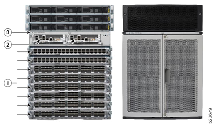
Refer to Figure 1 and Figure 2). RP0 is the slot on the left, facing the front of the chassis, and RP1 is the slot on right.
Figure 1. Redundant set of RP installed in slots RP0 and RP1 in a Cisco 8608 8-slot centralized chassis
Figure 2. Redundant set of RP installed in slots RP0 and RP1 in a Cisco 8808 8-slot distributed chassis
1
Modular Port Adaptors (MPAs)
2
Route Processors (RPs)
3
Chassis
Active RP
The active RP manages the system and communicates with the user interface.
Standby RP
The standby RP maintains a complete backup of the software and configurations for all cards in the system. If the active RP fails or goes offline for any reason, the standby RP immediately takes control of the system.