Content Engine Network Module for Caching and Content Delivery
Available Languages
Table Of Contents
Content Engine Network Module for Caching and Content Delivery
Prerequisites for the Content Engine Network Module for Caching and Content Delivery
Restrictions for the Content Engine Network Module for Caching and Content Delivery
Information About the Content Engine Network Module for Caching and Content Delivery
Cisco Content Delivery Networks
CE Network Module Operating Topologies
How to Configure and Manage the Content Engine Network Module for Caching and Content Delivery
Configuring IP Addresses on the CE Network Module Interfaces
Opening a Console Access Session to Configure the CE Network Module
Managing the CE Network Module
Installing Cisco ACNS Software on a CE Network Module with a SCSI Expansion Module
Installing Cisco ACNS Software from a CD-ROM or from Cisco.com
Installing Cisco ACNS Software from Compact Flash
Recovering a Corrupted ACNS Software Image
Installing a Hot-Swappable CE Network Module (Cisco 3660 and Cisco 3745 Only)
Configuration Examples for the Content Engine Network Module for Caching and Content Delivery
Content Engine Network Module for Caching and Content Delivery
The Content Engine Network Module for Caching and Content Delivery feature integrates content engine (CE) functionality into branch office routers for enterprise and service provider sites. Content engine functionality provides the following benefits:
•
Reduced bottlenecks and increased available bandwidth
•
Transferring content engine capabilities from a router-attached appliance to an integrated network module provides the following benefits:
•
•
•
•
Feature Specifications for the Content Engine Network Module for Caching and Content Delivery
Determining Platform Support Through Cisco Feature Navigator
Cisco IOS software is packaged in feature sets that are supported on specific platforms. To get updated information regarding platform support for this feature, access Cisco Feature Navigator. Cisco Feature Navigator dynamically updates the list of supported platforms as new platform support is added for the feature.
Cisco Feature Navigator is a web-based tool that enables you to determine which Cisco IOS software images support a specific set of features and which features are supported in a specific Cisco IOS image. You can search by feature or release. Under the release section, you can compare releases side by side to display both the features unique to each software release and the features in common.
To access Cisco Feature Navigator, you must have an account on Cisco.com. If you have forgotten or lost your account information, send a blank e-mail to cco-locksmith@cisco.com. An automatic check will verify that your e-mail address is registered with Cisco.com. If the check is successful, account details with a new random password will be e-mailed to you. Qualified users can establish an account on Cisco.com by following the directions found at this URL:
Cisco Feature Navigator is updated regularly when major Cisco IOS software releases and technology releases occur. For the most current information, go to the Cisco Feature Navigator home page at the following URL:
Availability of Cisco IOS Software Images
Platform support for particular Cisco IOS software releases is dependent on the availability of the software images for those platforms. Software images for some platforms may be deferred, delayed, or changed without prior notice. For updated information about platform support and availability of software images for each Cisco IOS software release, refer to the online release notes or, if supported, Cisco Feature Navigator.
Contents
•
•
•
•
•
Prerequisites for the Content Engine Network Module for Caching and Content Delivery
•
•
•
•
Restrictions for the Content Engine Network Module for Caching and Content Delivery
•
•
•
•
•
•
Information About the Content Engine Network Module for Caching and Content Delivery
The CE network module is specialized to run an integrated enterprise content delivery network (E-CDN) application on a Cisco Application and Content Networking System (ACNS) software platform that includes content-caching and content-delivery software.
The first task for the CE network module is to define IP addresses and subnet masks for the CE network module interfaces. Because the CE network module does not have direct console access, this is a necessary first step to allow access so that you can configure ACNS software on the CE itself.
After defining IP addresses, ensure that ACNS software Version 4.2.3 or a later release is loaded on the CE network module. The type of storage memory that your CE network module employs determines how the ACNS software is installed, as follows:
•
•
The following concepts are helpful in understanding the CE network module:
•
Cisco Content Delivery Networks
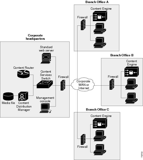
When a Cisco E-CDN application is enabled, a combination of content engines, content routers, content services switches, and content distribution managers can be deployed to create a complete content delivery network system that includes content routing, content switching, content distribution and management, and content services, as well as content delivery. The CE network module is one element of that network. Figure 1 shows a typical E-CDN topology.
Cisco ACNS software unifies caching software and Cisco E-CDN software into a single software platform that is supported on content engines, content distribution managers, and content routers. ACNS software accelerates content delivery and optimizes bandwidth usage by caching frequently accessed content and fulfilling content requests locally rather than traversing the Internet or intranet to a distant server each time a request is made. The ACNS software cache application works in tandem with Cisco IOS routing software to handle web traffic, including user requests to view pages and graphics (objects) on World Wide Web servers—whether the traffic is internal or external to your network.
In addition to relieving WAN bottlenecks with localized caching, Cisco CEs can become the content delivery elements of a Cisco content delivery network (CDN) solution. CDN solutions enable the proactive distribution of rich media files to content engines at the network edge for local access. Primary CDN applications include e-learning, corporate communications, and software distribution. Designed for affordability and ease of installation, a CDN solution enables you to quickly deploy high-impact, high-bandwidth rich media, such as high-quality streaming video—with minimal administration.
The CE network module is completely interoperable with other CE appliances and components of an E-CDN. CE network module hardware is based on Cisco CE-507 and CE-560 architecture, uses an Intel Mobile Pentium III microprocessor, and runs under a Linux operating system.
For more information, refer to the following:
•
•
•
•
Figure 1 Cisco Enterprise Content Delivery Network Topology
Cisco Content Engines
Cisco CEs, including CE network modules, accelerate content delivery and optimize bandwidth usage in the following two ways:
•
•
The CE leverages interception mechanisms based on Cisco IOS software to handle requests for web traffic—whether internal or external to your network. In addition, Cisco CEs can be deployed in reverse proxy mode in front of web servers to dramatically increase performance. By transparently caching inbound requests for content, CEs can offload a significant amount of traffic and number of TCP connections from origin servers. CEs dynamically distribute web content to eliminate bottlenecks and to speed access to content using this type of scenario:
1.
2.
3.
4.
By caching web objects in this manner, the CE can speed the satisfaction of user requests when more than one user wants to access the same object. Caching in this manner also reduces the amount of traffic between your network and the Internet, potentially improving your overall network performance and optimizing your bandwidth usage, typically resulting in WAN bandwidth savings of 25 to 60 percent.
CE Network Module Hardware
The CE network module occupies a single router slot and has the properties that are summarized in Table 2.
External hardware interfaces include the following:
•
•
•
CE Network Module Operating Topologies
The CE network module can be deployed by branch office customers in one of the following topologies:
•
Similar to situations in which a PC is connected to a LAN, the Ethernet interface on the CE network module is given an IP address from the branch office's LAN IP subnet space, which is typically configured statically using the Cisco IOS command-line interface (CLI) on the console port. One advantage of this topology is that the Fast Ethernet port on the CE network module can operate at line speed. The only communication between the router and the CE network module is in the form of keepalives or heartbeats that are processed through the internal FE ports. All caching and streaming traffic goes through the external FE port.
•
In this topology, the Ethernet interface is given an address from an IP subnet separate from the branch office LAN subnet. All caching and streaming traffic flows through the router. The CE's performance is limited by the router's switching performance. In this scenario, streaming and caching traffic, as well as keepalive traffic, goes through internal FE ports. Caching and streaming traffic uses router resources such as CPU, SDRAM bandwidth, and backplane PCI bandwidth.
CE Network Module Interfaces
The CE network module uses three interfaces for communication, as shown in Figure 2. Two of the interfaces enable internal administrative and management traffic between the router (Cisco IOS) and the CE (Cisco ACNS software) over an internal Ethernet segment. The third interface is the external link that supports CE functionality.
Note that the interfaces within the "Router" box in Figure 2 are managed by Cisco IOS, while the interfaces within the "CE Network Module" box are managed by the CE CLI (Cisco ACNS software).
Figure 2 CE Network Module Interfaces
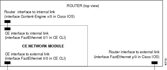
The router-side interface for the internal Ethernet segment is known as interface Content-Engine in the Cisco IOS software. This interface is the only interface associated with the CE that is visible in the output of the show interfaces command. It provides access through the Cisco IOS software to configure the CE interfaces with IP addresses and a default gateway. The router-side internal interface is connected to the router PCI backplane and is managed by Cisco IOS CLI.
The CE side of the internal Ethernet segment is called interface FastEthernet 0/1 in the CE CLI (Cisco ACNS software). When packets are sent from the router to the CE, they are sent out from the router on interface Content-Engine and received at the CE on interface FastEthernet 0/1. When packets are sent from the CE to the router, they are sent out from the CE on interface FastEthernet 0/1 and received at the router on interface Content-Engine. The internal CE-side interface is connected to the PCI bus on the CE side, and it is managed by the CE software. Only the IP address is configured from Cisco IOS CLI. All other configurations are performed from the CE CLI or from the CE graphical user interface (GUI). Bandwidth, autosense, and duplex settings are not allowed on this interface.
The external CE interface is known as interface FastEthernet 0/0 in the CE CLI (Cisco ACNS software). This is the Ethernet port on the network module, and it supports data requests and transfers from outside sources. This link provides direct Fast Ethernet connectivity to the LAN through an RJ-45 connector. Only the IP address is configured from Cisco IOS CLI; all other configurations are performed from the CE CLI or from the CE GUI.
How to Configure and Manage the Content Engine Network Module for Caching and Content Delivery
Refer to the following sections for configuration, installation, and troubleshooting tasks for the CE network module. Each task in the list is identified as either required or optional.
•
•
•
•
•
•
•
Configuring IP Addresses on the CE Network Module Interfaces
In this procedure, IP addresses are configured on the three CE network module interfaces shown in Figure 2:
•
•
•
SUMMARY STEPS
1.
2.
3.
4.
5.
6.
7.
8.
DETAILED STEPS
Opening a Console Access Session to Configure the CE Network Module
The CE network module is a standalone content engine with its own startup and run-time configurations that are independent of the Cisco IOS configuration on the router. Although IP addresses are defined on the CE network module interfaces through the router's Cisco IOS CLI, as explained in the "Configuring IP Addresses on the CE Network Module Interfaces" section, the CE itself is configured in the same way that standalone CE appliances are configured, with a combination of CE CLI and web-based GUI. The software to configure CEs is known as Cisco Application and Content Networking System (ACNS) software.
The CE network module differs from a standalone CE appliance because it does not have an external console port. Console access to the CE network module is enabled when you issue the service-module content-engine session command on the router, as explained in this section, or when you initiate a Telnet connection. The lack of an external console port means that the initial boot-up configuration is possible only through the router.
When you issue the service-module content-engine session command, you create a console session with the CE, in which you can issue any of the CE configuration commands. After completing work in the session and exiting the CE software, you are returned to Cisco IOS CLI, where you must clear the session using the service-module content-engine session clear command.

Timesaver
SUMMARY STEPS
1.
2.
3.
4.
DETAILED STEPS
Step 1
service-module content-engine slot/unit session
Example:Router# service-module content-engine 4/0 session
Trying 10.10.10.1, 2129 ... Open
CE-netmodule con now available
Press RETURN to get started!
CE-netmodule> enable
CE-netmodule#
Provides console access to the CE network module from the router CLI by initiating a reverse Telnet connection. This command places you in CE CLI configuration mode. After using the enable command, you are in CE CLI privileged EXEC mode.
The reverse Telnet connection is made using the IP address of the CE interface and the terminal (TTY) line associated with the CE network module. The TTY line number is calculated using the following formula (n*32)+1, where n is the number of the chassis slot that contains the CE network module. In the example output provided in this step, the CE interface IP address is 10.10.10.1, and the TTY line number is 129. The number 2000 has been added to the TTY line number for the reverse Telnet session.
The arguments are as follows:
•
•
The CE interface must be up before you can use the service-module content-engine session command.
Once a session is started, you can perform any CE configuration task. You first access the CE console in a user-level shell. The enable command takes you to the privileged EXEC command shell, where most commands are available.
Step 2
Enter ACNS configuration commands at the CE-netmodule prompt.
CE configuration tasks are described in documentation for the appropriate version of Cisco ACNS software at the following URL: http://www.cisco.com/univercd/cc/td/doc/product/webscale/uce/
Step 3
Press Control-Shift-6, and then press x to return to router configuration.
The CE session stays up until you use the service-module content-engine session clear command as described in Step 4. While the CE session remains up, you can use Enter to return to the CE session from router configuration.
Step 4
service-module content-engine slot/unit session clear
Example:Router# service-module content-engine 4/0 session clear
Clears the existing CE network module configuration session. Use this command after exiting the CE module as described in Step 2. The arguments are as follows:
•
•
Press Enter when you are asked to confirm this command.
Managing the CE Network Module
The commands in this section are used for the graceful shutdown, reset, and reload of a CE network module after it has been installed. For information on installation, refer to the following documents:
•
•
•
SUMMARY STEPS
Use the following commands as necessary:
•
•
•
DETAILED STEPS
Installing Cisco ACNS Software on a CE Network Module with a SCSI Expansion Module
A Cisco CE network module with an installed SCSI controller expansion module does not ship with installed ACNS software. If you have this type of CE network module, you also require an external storage array to hold the ACNS software.
Before using the CE network module, you need to install an external storage array and the Cisco ACNS software. ACNS software is installed by one of the following methods:
•
•
•
Installing Cisco ACNS Software from a CD-ROM or from Cisco.com
To perform the Cisco ACNS software installation from a CD-ROM or from Cisco.com, you need a local FTP server that can be reached from the router that contains the CE network module. The local FTP server should be configured with a valid username and password.
The external storage array is also installed during this procedure.

Note
SUMMARY STEPS
1.
2.
3.
4.
5.
6.
7.
8.
9.
10.
DETAILED STEPS
Step 1
•
•
Step 2
Note
The following example shows how to enter CE CLI privileged EXEC mode for the CE network module in slot 4 and then shows the two commands that you can use to establish baseline disk usage. An example of the output from the two commands is shown in Step 6.
Router# service-module content-engine 4/0 sessionTrying 10.10.10.1, 2129 ... OpenCE-netmodule con now availablePress RETURN to get started!CE-netmodule> enable
Password:
CE-netmodule# show disksCE-netmodule# show disks detailsStep 3
Step 4
•
CE-netmodule# reload•
Router# service-module content-engine 4/0 reloadDo you want to proceed with reload?[confirm]Step 5
Step 6
•
CE-netmodule# show disksSYSFS 0.0GB 0.0%CFS 0.0GB 0.0%MEDIAFS 0.0GB 0.0%ECDNFS 0.0GB 0.0%FREE 113.7GB 100.0%•
CE-netmodule# show disks detailsdisk00:Normal (h00 c00 i08 l00) 17364MB( 17.0GB)System use: 3317MB( 3.2GB)FREE: 14046MB( 13.7GB)disk01:Normal (h00 c00 i09 l00) 17366MB( 17.0GB)disk01/00:SYSFS 17365MB( 17.0GB) mounted at /local1FREE: 0MB( 0.0GB)disk02:Normal (h00 c00 i10 l00) 17366MB( 17.0GB)disk02/00:SYSFS 17365MB( 17.0GB) mounted at /local2FREE: 0MB( 0.0GB)disk03:Normal (h00 c00 i11 l00) 17366MB( 17.0GB)disk03/00:SYSFS 17365MB( 17.0GB) mounted at /local3FREE: 0MB( 0.0GB)disk04:Normal (h00 c00 i11 l00) 17366MB( 17.0GB)disk03/00:SYSFS 17365MB( 17.0GB) mounted at /local4FREE: 0MB( 0.0GB)disk05:Normal (h00 c00 i13 l00) 17366MB( 17.0GB)disk05/00:SYSFS 17365MB( 17.0GB) mounted at /local5FREE: 0MB( 0.0GB)If the external storage array is not detected by the network module, verify that the SCSI cables are connected and that the external storage array is operational. For more information on troubleshooting the external storage array, refer to the Cisco Storage Array 6 Installation and Configuration Guide.
Step 7
CE-netmodule# disk recoverStep 8
CE-netmodule# copy ftp install server4 /images acns_fileStep 9
Step 10
Installing Cisco ACNS Software from Compact Flash
If you do not have an FTP server available in the network or if the CE network module does not have network connectivity, you can install the ACNS software image from an external compact Flash card, Cisco part number MEM-256CF-x.x-K9=, where x.x is the Cisco ACNS software version.
SUMMARY STEPS
1.
2.
3.
a.
b.
c.
d.
4.
5.
6.
DETAILED STEPS
Step 1
Step 2
•
CE-netmodule# reload•
Router# service-module content-engine 4/0 reloadDo you want to proceed with reload?[confirm]Step 3
a.
b.
c.
d.
Router# service-module content-engine 4/0 sessionTrying 10.10.10.1, 2129 ... OpenCE-netmodule con now availablePress RETURN to get started!CE-netmodule> enable
Password:
CE-netmodule# cd flash1CE-netmodule# dirThe dir command displays the list of files in the compact Flash memory. The following example shows the output from a dir command.
CE-netmodule# dirsize time of last change name-------------- ------------------------- -----------12290784 Mon Jan 7 03:22:38 1980 sys422.img105990784 Mon Jan 7 03:22:38 1980 acns422.imgStep 4
CE-netmodule# copy compactflash install acns4xx.imgStep 5
Step 6
Recovering a Corrupted ACNS Software Image
An ACNS software image can become corrupted if there is a power failure or other interruption during an operation in which the image is being written to the CE network module's onboard StrataFlash memory, such as during an ACNS software installation or upgrade.
If the ACNS software image on the CE network module's onboard StrataFlash memory is corrupted, the network module boots up using a special rescue image that is also located on the onboard StrataFlash memory. The rescue image serves a limited purpose, which is simply to download a fresh Flash component of the ACNS software image and write it to the onboard StrataFlash memory. The rescue image can download this Flash component either from an FTP server on the network or from an external compact Flash card that is installed locally.
If you are going to download the Flash component from an FTP server on the network, the Flash component must first be downloaded to an FTP server from a CD-ROM or from Cisco.com over the network. This procedure and the procedure to download the image from the FTP server to the onboard Flash memory are the same as those described in the "Installing Cisco ACNS Software from a CD-ROM or from Cisco.com" section.
If you do not have an FTP server available in the network or if the network module does not have network connectivity, you can recover the ACNS software image from a special external compact Flash card, Cisco part number MEM-256CF-x.x-K9=, where x.x is the Cisco ACNS software version number.
SUMMARY STEPS
1.
2.
3.
4.
5.
6.
7.
8.
DETAILED STEPS
Step 1
Insert the compact Flash card in the compact Flash slot on the front of the network module.
Freeing initrd memory:208k freedVFS:Mounted root (ext2 filesystem).Freeing unused kernel memory:448k freedThis is the rescue image. The purpose of this software is to letyou install a new system image onto your system's boot flashdevice. This software has been invoked either manually(if you entered `***' to the bootloader prompt) or hasbeen invoked by the bootloader if it discovered that your system imagein flash had been corrupted.You now have the following options.1. Download an image from the network and install it to flash2. Insert a DOS formatted compact flash with a good systemimage on it, and install this image to flash. (Thesystem must be rebooted to detect the compact flash).3. Display diagnostic information about this system4. Reboot the systementer choice:Step 2
Step 3
Step 4
Please enter the directory containing the image file on the compact flash:[Enter directory on compact flash (e.g. /)]: /Step 5
Please enter the file name of the system image file on the compact flash:[Enter filename on compact flash]: ACNS-5.0.3-K9.sysimgStep 6
Trying to access the file //ACNS-5.0.3-K9.sysimg...Read 12290784 byte image fileA new system image has been read from compact flash.You should write it to system flash at this time.Please enter 'yes' below to indicate that this is what you want to do:yesStep 7
Step 8
Installing a Hot-Swappable CE Network Module (Cisco 3660 and Cisco 3745 Only)
Some Cisco modular access routers allow you to replace network modules without switching off the router or affecting the operation of other interfaces. This feature is often called hot-swapping or online insertion and removal (OIR). Hot-swapping of network modules provides uninterrupted operation to network users, maintains routing information, and ensures session preservation.
Note

Caution
Caution
For a description of informational messages and error messages that may appear on the console during this procedure, refer to the hardware installation guide for your type of router.
SUMMARY STEPS
1.
2.
3.
4.
5.
6.
a.
b.
c.
7.
8.
9.
10.
11.
12.
13.
14.
15.
16.
17.
DETAILED STEPS
Step 1
Router# service-module content-engine 4/0 sessionTrying 10.10.10.1, 2129 ... OpenCE-netmodule con now availablePress RETURN to get started!CE-netmodule> enablePassword:CE-netmodule#Step 2
CE-netmodule# copy running-config tftp //server12/configs/rtr11-confgStep 3
Step 4
Router# service-module content-engine 4/0 session clear
Step 5
Router# service-module content-engine 4/0 shutdownStep 6
Router(config)# interface content-engine 4/0Router(config-if)# shutdownRouter(config-if)# exitStep 7
Step 8
Step 9
Step 10
Note
Step 11
Step 12
Step 13
Step 14
Router# service-module content-engine 4/0 sessionTrying 10.10.10.1, 2129 ... OpenCE-netmodule con now availablePress RETURN to get started!CE-netmodule> enable Password:CE-netmodule#Step 15
CE-netmodule# copy tftp running-config //server12/configs/rtr11-confgStep 16
Step 17
Router# service-module content-engine 1/0 session clear
Troubleshooting Tips
To diagnose problems with CE network module operation, use the commands and actions in this section.
•
•
Router# show versionCisco Internetwork Operating System SoftwareIOS (tm) C2600 Software (C2600-IS-M), Version 12.2(11)YT, RELEASE SOFTWARE (fc1)TAC Support: http://www.cisco.com/tacCopyright (c) 1986-2002 by cisco Systems, Inc.Compiled Thu 12-Sep-02 21:34 by axpoImage text-base: 0x80008098, data-base: 0x818AF44CROM: System Bootstrap, Version 12.1(3r)T2, RELEASE SOFTWARE (fc1)router-2621 uptime is 10 minutesSystem returned to ROM by power-onSystem image file is "flash:c2600-is-mz"cisco 2621 (MPC860) processor (revision 0x200) with 60416K/5120K bytes of memory.Processor board ID JAD051516TV (4151953086)M860 processor: part number 0, mask 49Bridging software.X.25 software, Version 3.0.0.2 FastEthernet/IEEE 802.3 interface(s)1 terminal line(s)1 cisco content engine(s)32K bytes of non-volatile configuration memory.16384K bytes of processor board System flash (Read/Write)Configuration register is 0x0•
•
•
•
Router# show diag 1Slot 1:Content Engine Port adapter, 1 portPort adapter is analyzedPort adapter insertion time unknownEEPROM contents at hardware discovery:Hardware Revision : 1.0Top Assy. Part Number : 800-20382-01Board Revision : A0Deviation Number : 0-0Fab Version : 02PCB Serial Number : JAB060605C4RMA Test History : 00RMA Number : 0-0-0-0RMA History : 00EEPROM format version 4EEPROM contents (hex):0x00: 04 FF 40 03 81 41 01 00 C0 46 03 20 00 4F 9E 010x10: 42 41 30 80 00 00 00 00 02 02 C1 8B 4A 41 42 300x20: 36 30 36 30 35 43 34 03 00 81 00 00 00 00 04 000x30: FF FF FF FF FF FF FF FF FF FF FF FF FF FF FF FF0x40: FF FF FF FF FF FF FF FF FF FF FF FF FF FF FF FF0x50: FF FF FF FF FF FF FF FF FF FF FF FF FF FF FF FF0x60: FF FF FF FF FF FF FF FF FF FF FF FF FF FF FF FF0x70: FF FF FF FF FF FF FF FF FF FF FF FF FF FF FF FF20GB IDE Disc Daughter CardHardware Revision : 1.0Top Assy. Part Number : 800-20520-01Board Revision : A0Deviation Number : 0-0Fab Version : 02PCB Serial Number : JAB060605A5RMA Test History : 00RMA Number : 0-0-0-0RMA History : 00EEPROM format version 4EEPROM contents (hex):0x00: 04 FF 40 03 83 41 01 00 C0 46 03 20 00 50 28 010x10: 42 41 30 80 00 00 00 00 02 02 C1 8B 4A 41 42 300x20: 36 30 36 30 35 41 35 03 00 81 00 00 00 00 04 000x30: FF FF FF FF FF FF FF FF FF FF FF FF FF FF FF FF0x40: FF FF FF FF FF FF FF FF FF FF FF FF FF FF FF FF0x50: FF FF FF FF FF FF FF FF FF FF FF FF FF FF FF FF0x60: FF FF FF FF FF FF FF FF FF FF FF FF FF FF FF FF0x70: FF FF FF FF FF FF FF FF FF FF FF FF FF FF FF FF•
•
•
•
Router# debug scp all*Mar 1 00:28:34.371: scp-tx: SA:0F/01 DA:01/01 Op:0012 Sq:0024 Ln:0004 I:00*Mar 1 00:28:34.371: 000: 02 5A 00 00 .Z..*Mar 1 00:28:34.371: scp-rx: SA:01/01 DA:0F/01 Op:0012 Sq:0024 Ln:0004 I:01*Mar 1 00:28:34.371: 000: 02 5A 00 00 .Z..Configuration Examples for the Content Engine Network Module for Caching and Content Delivery
This section provides the following configuration examples:
•
Note
Unnumbered IP Address Example
Figure 3 shows how the CE interfaces are configured using the unnumbered IP address method. In this example, the router interface to the internal router-CE link is configured using the ip unnumbered command to save IP address space. No new subnet needs to be defined for the internal network between the router and the CE. This configuration makes the CE interface that is pointing toward the Cisco IOS software an extension of the Fast Ethernet interface 0/0 of the router, which has an IP address of 10.10.10.2. When this method is used, a static IP route must be defined.
Figure 3 Unnumbered IP Address Example
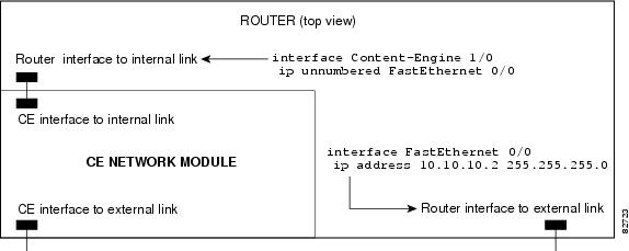
...!interface Content-Engine 1/0ip unnumbered FastEthernet 0/0service-module ip address 10.10.10.10 255.255.255.0service-module external ip address 172.18.12.20 255.255.255.0service-module ip default-gateway 10.10.10.2!ip route 10.10.10.10 255.255.255.255 Content-Engine 1/0!...Three IP Address Example
Figure 4 shows the configuration for the three IP address method. In this example, both the CE interface to the internal router-CE link and the router interface to the same link are on the 172.18.12.0/24 subnet. The external port of the CE network module is in the 10.3.0.0/16 subnet. Notice that there is no connection between the internal router interface to the CE and the external router interface in this configuration.
Figure 4 Three IP Address Example
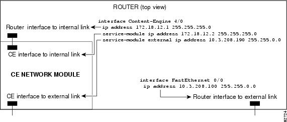
...!interface Content-Engine 4/0ip address 172.18.12.1 255.255.255.0service-module ip address 172.18.12.2 255.255.255.0service-module external ip address 10.3.208.190 255.255.0.0service-module ip default-gateway 10.3.0.1!..Additional References
For additional information related to the Content Engine Network Module for Caching and Content Delivery, refer to the following references:
Related Documents
Related content delivery products
Cisco ACNS software
Refer to
documentation for the appropriate version of Cisco ACNS software at the following URL:
http://www.cisco.com/univercd/cc/td/doc/product/webscale/uce/
E-CDN application software within a content delivery network
Cisco Content Delivery Networks
The Cisco Content Delivery Network Solution for the Enterprise
Cisco Content Networking technologies (web site)
Overview and installation of Content Delivery Networking products
Cisco Content Delivery Networking Products Getting Started Guide
Installing CE network modules
Connecting CE Network Modules for Caching and Content Delivery
Installing CE network module expansion modules
Installing Expansion Modules on the Cisco CE Network Module for Caching and Content Delivery
Installing CE network module memory modules
Installing SODIMM Memory Modules in Cisco Network Modules for Caching and Content Delivery
Installing network modules
Installing storage arrays
Cisco 2600 series
Cisco 3600 series
Cisco 3700 series
Standards
No new or modified standards are supported by this feature, and support for existing standards has not been modified by this feature.
—
1 Not all supported standards are listed.
MIBs
•
•
•
•
•
To obtain lists of supported MIBs by platform and Cisco IOS release, and to download MIB modules, go to the Cisco MIB website on Cisco.com at the following URL:
http://www.cisco.com/public/sw-center/netmgmt/cmtk/mibs.shtml
1 Not all supported MIBs are listed.
To locate and download MIBs for selected platforms, Cisco IOS releases, and feature sets, use Cisco MIB Locator found at the following URL:
http://tools.cisco.com/ITDIT/MIBS/servlet/index
If Cisco MIB Locator does not support the MIB information that you need, you can also obtain a list of supported MIBs and download MIBs from the Cisco MIBs page at the following URL:
http://www.cisco.com/public/sw-center/netmgmt/cmtk/mibs.shtml
To access Cisco MIB Locator, you must have an account on Cisco.com. If you have forgotten or lost your account information, send a blank e-mail to cco-locksmith@cisco.com. An automatic check will verify that your e-mail address is registered with Cisco.com. If the check is successful, account details with a new random password will be e-mailed to you. Qualified users can establish an account on Cisco.com by following the directions found at this URL:
RFCs
No new or modified RFCs are supported by this feature, and support for existing RFCs has not been modified by this feature.
—
1 Not all supported RFCs are listed.
Technical Assistance
Command Reference
The following new and modified commands are pertinent to this feature. To see the command pages for these commands and other commands used with this feature, go to the Cisco IOS Master Commands List, Release 12.4, at http://www.cisco.com/univercd/cc/td/doc/product/software/ios124/124mindx/
124index.htm.New Commands
•
•
•
•
•
•
•
•
•
•
•
Modified Command
•
Glossary
ACNS—Cisco Application and Content Networking System. ACNS is a software platform that unifies the Cisco cache software and Cisco enterprise content delivery network (E-CDN) software into a single software platform. ACNS software allows you to access caching application features and E-CDN application features from a single software base. ACNS software is supported on content engines, content distribution managers, and content routers.
CDM—Cisco Content Distribution Manager. Management program that provides a browser-based user interface to configure and monitor content engines and content routers and to control and manage content switching, content distribution and delivery, and content services.
CDN—content delivery network. Content delivery networks help accelerate the delivery of advanced content by deploying five key components: content switching, content routing, content edge nodes, content distribution and management, and intelligent network services. Content edge nodes are content engines that are typically placed in the branch office, like the CE network module.
CE—content engine. Edge appliance for delivering live or on-demand streaming media and other rich file formats to the desktop.
E-CDN—enterprise content delivery network. Enterprise CDNs (also known as intranet CDNs) apply caching and multicasting technology in a corporate LAN/WAN environment to distribute video and other content-rich files in ways that help minimize WAN bottlenecks, while taking advantage of the relatively abundant bandwidth of the LANs close to users.
WCCP—Web Cache Communication Protocol. Developed by Cisco Systems, WCCP specifies interactions between one or more routers (or Layer 3 switches) and one or more web caches. The purpose of the interaction is to establish and maintain the transparent redirection of selected types of traffic flowing through a group of routers. The selected traffic is redirected to a group of web caches with the aim of optimizing resource usage and lowering response times.
Cisco and the Cisco Logo are trademarks of Cisco Systems, Inc. and/or its affiliates in the U.S. and other countries. A listing of Cisco's trademarks can be found at www.cisco.com/go/trademarks. Third party trademarks mentioned are the property of their respective owners. The use of the word partner does not imply a partnership relationship between Cisco and any other company. (1005R)
© 2005 Cisco Systems, Inc. All rights reserved.
 Feedback
Contact Cisco
- Open a Support Case

- (Requires a Cisco Service Contract)
This Document Applies to These Products
- Collaboration Endpoints - Retired Products
- Conferencing - Retired Products
- Contact Center - Retired Products
- Optical Networking - Retired Products
- Routers - Retired Products
- Security - Retired Products
- Servers - Unified Computing (UCS) Retired Products
- Storage Networking Retired Products
- Switches - Retired Products
- Video - Retired Products
- Wireless - Retired Products