Configure the Cisco Fabric Border Provider Edge (BorderPE) for VXLAN EVPN Fabric White Paper
Available Languages
Bias-Free Language
The documentation set for this product strives to use bias-free language. For the purposes of this documentation set, bias-free is defined as language that does not imply discrimination based on age, disability, gender, racial identity, ethnic identity, sexual orientation, socioeconomic status, and intersectionality. Exceptions may be present in the documentation due to language that is hardcoded in the user interfaces of the product software, language used based on RFP documentation, or language that is used by a referenced third-party product. Learn more about how Cisco is using Inclusive Language.
- US/Canada 800-553-2447
- Worldwide Support Phone Numbers
- All Tools
 Feedback
 Feedback
What You Will Learn
This document describes how to integrate Virtual Extensible LAN (VXLAN) Ethernet Virtual Private Network (EVPN) fabric with Multiprotocol Label Switching (MPLS) and Segment Routing (SR) with Layer 3 VPN (L3VPN) using the Cisco® Fabric Border Provider Edge (BorderPE) feature. It also provides a configuration example to demonstrate the process.
The VXLAN EVPN fabric can be connected across Layer 3 boundaries using MPLS-LDP with L3VPN, MPLS-SR with L3VPN, SRv6 with L3VPN or Virtual Routing and Forwarding (VRF) IP routing (VRF-lite). This document focused on Layer 3 fabric connectivity using MPLS-LDP, MPLS-SR and SRv6 all with L3VPN.
Prerequisites
This document assumes that the reader is already familiar with the configuration of VXLAN EVPN data center fabric. The VXLAN EVPN fabric can be configured either manually or using Cisco Data Center Network Manager (DCNM). This document focuses entirely on providing external Layer 3 connectivity to the fabric with the assumption that the data center fabric is already configured and working on all devices, including the border leaf and spine nodes.
Introduction
Every fabric needs external connectivity to the campus or data center core network. Before the introduction of the Cisco Border Provider Edge feature for VXLAN EVPN running on Cisco Nexus® 9000 Series Switches, external Layer 3 connectivity required a VRF-lite two-device-based approach. Each fabric VRF instance was extended with a subinterface per instance along with Interior Gateway Protocol (IGP) or External Border Gateway Protocol (eBGP) peering between the border leaf and border spine and the edge router. In many two-device deployments, the edge router acts as an MPLS provider edge node. In deployments with a very large number of extended VRF instances, the number of eBGP sessions or IGP neighbors can cause scalability problems and configuration complexity.
To address the potential drawbacks of two-device solutions, Cisco has extended the external Layer 3 connectivity solution portfolio with a new single-device solution. This solution, the VXLAN EVPN BorderPE node, merges the border leaf and border spine and the MPLS provider edge router into a single device to provide Layer 3 external connectivity to data center fabric. Figures 1 and 2 compare the new single-device VXLAN EVPN BorderPE solution to the two-device solution in an MPLS campus or core scenario. We are using MPLS interchangibly for MPLS with Label Distribution Protocol (LDP) or MPLS with Segment Routing. Given similar Border PE function is present with Segment Routing for IPv6 (SRv6), the same document also encompasses these deployment scenarios.

Hardware and Software Requirements
This section lists the requirements for a VXLAN EVPN BorderPE deployment.
VXLAN EVPN BorderPE Requirements
Table 1. BorderPE Minimum Software and Hardware Solution Requirements
| Cisco Nexus Hardware |
Cisco NX-OS Software |
| Cisco Nexus 9300 FX2/FX3 Series Switches
● MPLS SR
|
Cisco NX-OS Release 9.3(1) or later |
| Cisco Nexus 9300 GX Series Switches
● MPLS SR
● SRv6
|
Cisco NX-OS Release 9.3(1) or later |
| Cisco Nexus 3600-R Series Switches
● MPLS LDP
● MPLS SR
|
Cisco NX-OS Release 9.3(1) or later |
| Cisco Nexus 9500-R Series Switches
● MPLS LDP
● MPLS SR
|
Cisco NX-OS Release 9.3(1) or later |
| Cisco Nexus 7000/7700 Series Switches with F3 or M3 line cards
● MPLS LDP
|
Cisco NX-OS Release depending on line cards
● F3-Series line cards: NX-OS 7.3(1)D1(1)
● M3-Series line cards: NX-OS 8.1(1)
|
Fabric and MPLS Network Requirements
This document does not cover the hardware and software requirements for the VXLAN EVPN fabric and the MPLS network. The following link provides access to the Cisco website, where you can find more information about fabric deployment: https://www.cisco.com/c/en/us/solutions/data-center-virtualization/index.html.
See the publically available documents on the Cisco website for additional information about MPLS network deployment.
VXLAN EVPN BorderPE Deployment Details
This section provides physical and logical overviews of a BorderPE deployment and an overview of BorderPE forwarding.
Physical Overview
Figure 3 shows the network topology used in this document to describe the BorderPE integration.
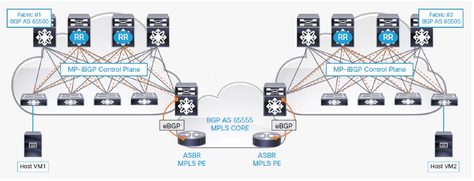
The programmable data center fabrics in Figure 3 are assigned to private autonomous system (AS) numbers 65500 and 65505 respectively and use a Clos architecture consisting of spine and leaf nodes. The configuration of these nodes is performed using either the command-line interface (CLI) or Data Center Network Manager power-on autoprovisioning (POAP) templates.
The Layer 3 VPN MPLS network in Figure 3 is assigned to autonomous system 65555 and is a simple MPLS network with provider (P) nodes and provider edge (PE) nodes. This document assumes that the MPLS network is already built and ready to use. The connectivity from the BorderPE in data center fabric 1 to the BorderPE in data center fabric 2 is already established using MPLS Label Distribution Protocol (LDP) or MPLS Segment Routing (SR) and IGP routing.
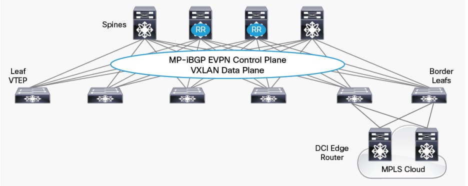
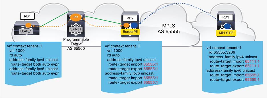
Each spine node in the fabric is deployed as an MP-BGP route reflector (RR) for the EVPN address family. The leaf nodes and BorderPE nodes peer with the fabric Multiprotocol BGP (MP-BGP) route reflectors. Within the data center fabric, an MP-BGP EVPN control plane provides host reachability information. This BGP EVPN control plane in the VXLAN EVPN fabric helps ensure distribution of routes between VXLAN tunnel endpoints (VTEPs) and the BorderPE nodes within the fabric. The leaf switches will forward the attached host IP and MAC addresses using the EVPN route type 2 option (for this route type, BGP has both the IP and MAC address information), including Layer 2 and Layer 3 VXLAN network identifiers (VNIs).
The two BorderPE nodes on the two fabrics are assigned to private autonomous systems 65500 and 65505 in the fabric respectively and provide redundant Layer 3 connectivity between the programmable fabric and the Layer 3 VPN MPLS network. The BorderPE nodes are configured with all the local VRF instances in the fabric, and on the basis of the import route-target (RT) values configured on the BorderPE, the switch will import the /32 routes into local VRF tables.
The BorderPE nodes peer with the MPLS service provider edge nodes using eBGP. The eBGP peering from the BorderPE nodes to the MPLS provider edge nodes supports eBGP multihop routing.
BorderPE Forwarding Details
The merge of the fabric border leaf node and the MPLS provider edge node into a single node requires the rewriting of the BGP route targets and the VPN route distinguisher (RD) attribute. This section briefly discusses these policies for the two forwarding directions. Attributes, such as site of origin and sequence number (used for host mobility), if they are available, are carried from the local fabric to external nodes and back to the fabric, or in the opposite direction, depending on the forwarding direction.
Forwarding from the Fabric to the MPLS Network
Figure 4, Table 2, and the following discussion present the steps used when a packet sourced in the fabric is forwarded to a fabric external destination.
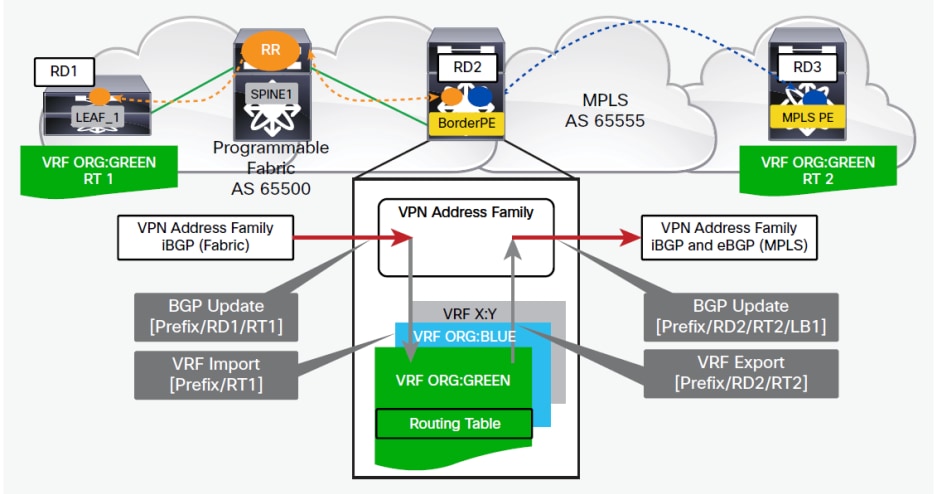
Table 2. Abbreviations Used in Figure 4
| Abbreviation |
Description |
|
● Prefix
|
IPv4/IPv6 route originating in the fabric |
|
● RD1
|
VPN route distinguisher for VRF ORG:GREEN on source leaf node |
|
● RD3
|
VPN route distinguisher for VRF ORG:GREEN on destination MPLS provider edge node |
|
● RT1
|
BGP route target for VRF ORG:GREEN |
|
● LB1
|
● VPNv4 MPLS label
|
When the BorderPE node receives a route from the fabric (sourced by a leaf node), the following steps are processed:
1. The EVPN type 2 routes (/32 host IP and MAC routes) are imported into the local VRF instance according to the BGP route-target filtering.
2. Imported routes are installed in the local routing information base (RIB) and forwarding information base (FIB) with specific fabric encapsulation information such as the virtual network segment ID (VNI). The VPN route distinguisher coming from the fabric side (AS 65500) is stripped off.
3. Imported routes are re-exported to the VPN address family, and a local VPNv4/v6 MPLS label is allocated.
4. Re-exported routes are advertised to eBGP peers with the allocated VPNv4/v6 MPLS label. (An eBGP neighborship exists between the BorderPE and the autonomous system boundary router (ASBR) in the MPLS cloud.)
5. Advertised VPNv4/v6 routes use the local VPN route distinguisher from the BorderPE node (not the incoming VPN route distinguisher from the leaf nodes). This local VPN route distinguisher has to be configured per VRF instance on the BorderPE node.
6. The per-VRF fabric-relevant BGP route target is stripped off.
Forwarding from the MPLS Network to the Fabric
Figure 5, Table 3, and the following discussion present the steps used when a packet sourced outside the fabric is forwarded to a destination internal to the fabric.
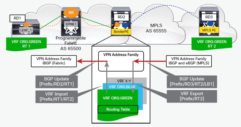
Table 3. Abbreviations Used in Figure 5
| Abbreviation |
Description |
|
● Prefix
|
IPv4/IPv6 route originating in the fabric |
|
● RD1
|
VPN route distinguisher for VRF ORG:GREEN on source leaf node |
|
● RD2
|
VPN route distinguisher for VRF ORG:GREEN on BorderPE node |
|
● RD3
|
VPN route distinguisher for VRF ORG:GREEN on destination MPLS provider edge node |
|
● RT1
|
● BGP route target for VRF ORG:GREEN
|
|
● LB1
|
● VPNv4 MPLS label
|
| LB1 |
VPNv4 MPLS label |
When the BorderPE node receives a route from the external fabric (sourced by an MPLS provider edge node), the following steps are processed:
1. Routes are imported into the local VRF instance according to the BGP route-target filtering.
2. Imported routes are installed in the local RIB and FIB with the MPLS label and the next hop from the default VRF instance resolved. The VPN route distinguisher coming from the MPLS side is stripped off.
3. Imported routes are re-exported into the VPN address family in the fabric. The BorderPE mode switches are configured to re-originate these imported VRF prefixes from the MPLS side toward the EVPN control plane on the fabric side.
4. Re-exported routes are advertised to fabric BGP peers in AS 65500 along with the fabric-specific encapsulation information such as the VN-segment ID (VNI).
5. The exported routes from the BorderPE toward the fabric side use the local VPN route distinguisher for that VRF instance from the BorderPE node (not the incoming VPN route distinguisher from the MPLS provider edge nodes).
6. The per-VRF MPLS network-relevant BGP route target is stripped off.
Configuration Example
This section summarizes the steps for configuring the BorderPE solution on a Cisco Nexus Switch using manual configuration without an overlay provisioning manager such as Virtual Topology System.
Step 1. Enable importing and exporting of routes per tenant VRF instance from the VXLAN fabric side to the MPLS side. The following settings should already be configured as part of the fabric configuration (create a VRF instance and associate a VNI with it) on the BorderPE nodes.
Now enable the importing and exporting of the VXLAN fabric side to the MPLS side on the BorderPE node.
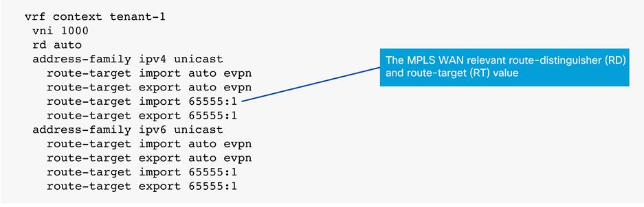
Figure 6 shows the configuration.
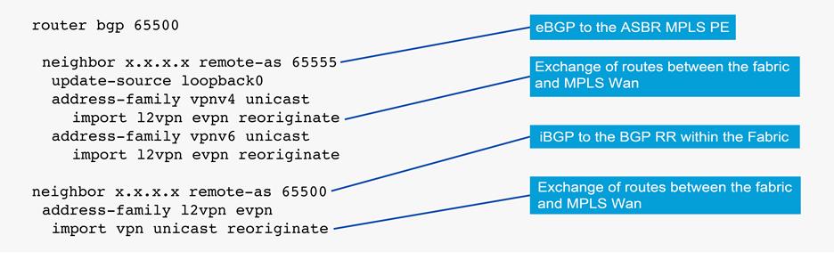
Step 2. Configure the BGP control plane on the BorderPE node.
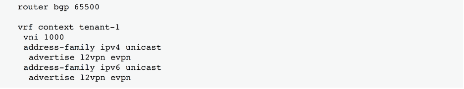
Step 3. Enable importing and exporting of routes per tenant VRF instance from the MPLS side to the VXLAN fabric side.
Conclusion
The BorderPE solution merges the border leaf and border spine and the MPLS provider edge into a single device to provide Layer 3 external connectivity to the data center fabric. The Cisco Nexus 9000 Series platform switches have comprehensive feature sets that can be used to implement the VXLAN-to-MPLS solution discussed in this document.
The Cisco Nexus 9000 Series provide multiple-data-plane encapsulation in hardware and control-plane protocols. VXLAN encapsulation is implemented in hardware on the southbound side, and MPLS is implemented in hardware on the northbound side, making the Cisco Nexus 9000 Series platform switches a excellent choices for this solution.