Cisco ACI Endpoint Security Group (ESG) Design Guide
Available Languages
Bias-Free Language
The documentation set for this product strives to use bias-free language. For the purposes of this documentation set, bias-free is defined as language that does not imply discrimination based on age, disability, gender, racial identity, ethnic identity, sexual orientation, socioeconomic status, and intersectionality. Exceptions may be present in the documentation due to language that is hardcoded in the user interfaces of the product software, language used based on RFP documentation, or language that is used by a referenced third-party product. Learn more about how Cisco is using Inclusive Language.
- US/Canada 800-553-2447
- Worldwide Support Phone Numbers
- All Tools
 Feedback
 Feedback
Contents
Network-centric to Application-centric Migration Story: Pseudo Co
Overview of Pseudo Company’s Cisco ACI Deployment
Endpoint Group vs Endpoint Security Group
Design Blueprint–Single ESG per Application
Step 1: Implement a single ESG for open communication between subnets (EPG selectors)
Step 2: Implement a single ESG for all endpoints of a single application (tag selectors)
Step 3: Communication between applications (contract between ESGs)
Step 4: Enforce additional application security
Flexible Security Zones with ESGs
Example 1: A security zone per VRF instance as a default zone (EPG selectors)
Example 2: A security zone per set of subnets/VLANs (EPG Selectors)
Example 3: Tag Selectors with VMM integration
Example 4: Tag selectors without VMM integration for VM endpoints using the MAC address
Example 5: Tag selectors without VMM integration for VM endpoints using the IP address
Example 6: Tag selectors for bare metal endpoints using the MAC address
Example 7: Tag selectors for bare metal endpoints using the IP address
Example 8: Tag selectors with intermediary switches
Example 9: IP subnet selectors
Example 11: Multiple security zones using EPG selectors with a quarantine ESG using tag selectors.
Example 12: ESG with Layer 2 multicast
Example 13: EPG Selectors and IP-based Selectors Without a VMM Domain
Appendix: Cisco ACI Tenant Design Examples Using ESGs
Example 1: All in a user tenant
Example 2: VRF instance/bridge domains/EPGs (VLANs) in tenant common while ESGs in user tenants
Example 4: Shared services in the same VRF instance from tenant common
Example 5 Shared services in a different VRF instance
This document describes Cisco® Application Centric Infrastructure (Cisco ACI®) Endpoint Security Group (ESG) use cases and deployment considerations.
This document assumes that the reader has a basic knowledge of Cisco ACI technology. For more information about Cisco ACI, see the Cisco ACI white papers available at Cisco.com.
This document focuses on ESGs and does not cover detailed contract configuration and design options. For more information about contracts, see the Cisco ACI Contract Guide.
For information about ESG configuration, see the Cisco APIC Security Configuration Guide, Release 6.0(x).
This document uses the following terms:
● TN: tenant
● VRF: virtual routing and forwarding
● BD: bridge domain
● EPG: endpoint group – a collection of endpoints attached to one or more VLANs within a BD
● ESG: endpoint security group – a collection of endpoints within a VRF instance
● EP: endpoint residing in a Cisco ACI fabric
● L3Out: Layer 3 Outside or external routed network
● L3Out/External EPG: subnet-based EPG in L3Out
● Border leaf switch: Cisco ACI leaf switch where an L3Out is deployed
● VMware vCenter VMM domain: virtual machine manager domain on Cisco ACI that maps to a virtual distributed switch (vDS) on VMware vCenter
● Application-centric design and network-centric design:
◦ In a typical network-centric design, a single EPG (security group) is created per bridge domain. The EPG typically contains a single VLAN ID, which is similar to a traditional network design. The network building blocks are named in a manner that reflects the network constructs, such as "epg-vlan-10, epg-vlan-11, epg-vlan-12".
◦ In an application-centric design, one or more EPGs/ESGs are created on the same bridge domain. The network building blocks are named in a way that reflects the application, such as "epg-web, epg-app, epg-db".
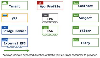
Figure 1 shows the icons used throughout this document. The object handles depict the following functions:
● C: Contract consumer
● CCI: Consumed contract interface
● I: Intra EPG/ESG contract
● P: Contract provider
The document covers features up to Cisco ACI release 6.0(2). The document is divided into several sections:
● Network Centric to Application Centric Migration Story: Pseudo Co explains one example of adopting ESGs in a Cisco ACI fabric for users new to ESGs.
● ESG Design Examples explains more ESG design examples for users familiar with ESGs.
● Appendix explains comprehensive Cisco ACI multi-tenant design examples.
Network-centric to Application-centric Migration Story: Pseudo Co
This section covers an EPG to ESG migration story using Pseudo Co a (fictitious) company that has historically been using Cisco ACI in a network-centric design with a single EPG per subnet.
See the ESG Design Examples section for other design options.
Overview of Pseudo Company’s Cisco ACI Deployment
Pseudo Co has configured several Cisco ACI tenants with numerous virtual machine endpoints on ESXi hosts that are directly attached to the Cisco ACI fabric.
The following figure provides a high-level overview of Pseudo Co’s Cisco ACI fabric and the attached devices:
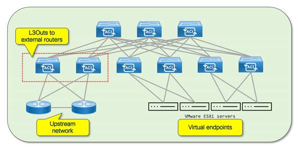
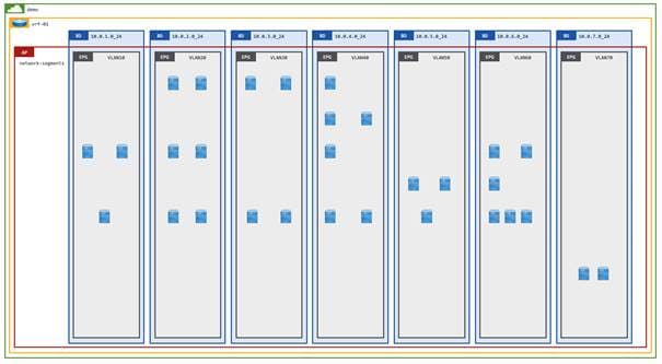
Pseudo Co has deployed its Cisco ACI fabric in what is commonly described as a network-centric design where there is a 1:1 mapping of bridge domains to EPGs. As part of the network implementation, Pseudo Co chose to implement a VMM domain to simplify the management of VLANs between the Cisco ACI fabric and the ESXi hosts. The Cisco APIC VMM domain dynamically allocates VLANs to the vDS port groups from a VLAN pool on Cisco APIC. Due to the dynamic VLAN allocation, it is often practical to implement a naming format where the BD_name = EPG_name. However, for the purposes of this document and to illustrate the function of the bridge domains and EPGs, this document uses the subnet CIDR for the bridge domain name and the VLAN ID for the EPG name:
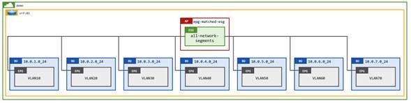
● Tenant: demo
● VRF: vrf-01
● Bridge domains: 10.0.1.0_24 – 10.0.7.0_24
● EPGs: VLAN10 – VLAN70
● EPs: Distributed across the different network segments
The following figure represents one of Pseudo Co’s tenants:
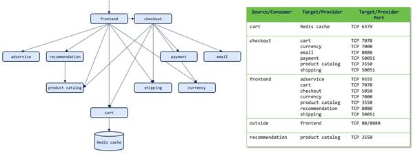
For this design guide, we will show how Pseudo Co easily converted its Cisco ACI fabric from a network-centric design to an application-centric design. The diagram below illustrates a multi-tier reference application (online-boutique) that will be used throughout this design guide.
Note: The reference application was inspired from this demo application on GitHub.
Consumer traffic to the online-boutique application uses the frontend service on ports 80/8080 as detailed in the accompanying table. The arrows between the application tiers detail the expected traffic flows, which is from the source/consumer to the target/provider.
The diagram below illustrates how the online boutique application has been deployed across the different network segments (subnets) within the "demo" tenant. Note that several application services, such as frontend, payment, and cart, span different subnets. Spreading endpoints across different subnets within Pseudo Co occurred because of exponential growth in the number of endpoints required for a given application tier. Application endpoints have crossed subnet boundaries due to IP address exhaustion within a given subnet.
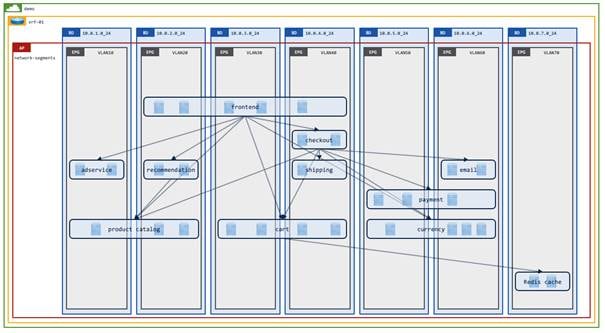
Applications such as the online boutique application that are hosted on Pseudo Co’s network-centric Cisco ACI fabric require open communication between the different application tiers to enable the application to function correctly.
There are several different configuration options available to enable open communication amongst many/all EPGs on a Cisco ACI fabric:
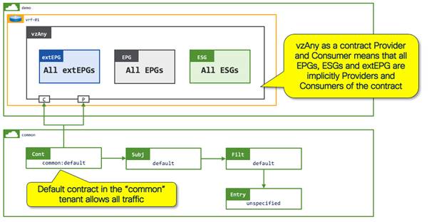
● Contract with vzAny: vzAny represents all EPGs, ESGs and external EPGs on a VRF instance. Providing and consuming an open "permit-any" contract on vzAny allows open communication between all endpoints on a VRF instance.
● Preferred Groups – Assigning multiple EPGs to a Preferred Group allows open communication between the EPGs in the Preferred Group, with the restriction that there can only be one Preferred Group per VRF instance.
● Disable security – We do not recommend this option because configuring the VRF instance to "unenforced" mode converts the VRF instance to "permit only," allowing open communication between all endpoints in the VRF instance. Disabling security implicitly disables security contracts and advanced functionality such as service graphs.
In addition to the above options, starting from Cisco ACI release 5.2(1g), you can use an ESG with EPG selectors to create a security group that aggregates several EPGs. Communication within a given ESG (intra-ESG communication) is permitted by default. The use case for EPG to ESG mapping is covered in detail later in this section.
Pseudo Co has currently enabled open communication within a VRF instance through the use of the vzAny, which provides and consumes the "default" contract from the "common" tenant as illustrated in the following figure:
Endpoint Group vs Endpoint Security Group
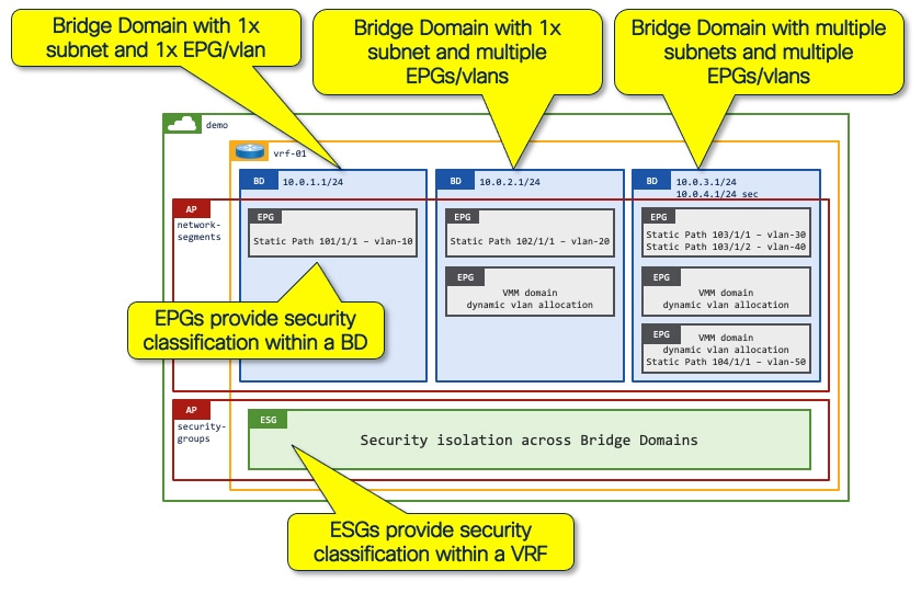
It is important to compare the functionality and design considerations of endpoint groups vs endpoint security groups. The basic building blocks of Cisco ACI (as detailed in the Figure below) dictate that:
● VRF instance: Can only exist in a single tenant.
● Bridge domain: Can only be mapped to a single VRF instance and can provide routing for one or more subnets (Secondary IP addresses).
● EPG: Defines a security group boundary within a bridge domain. Admission to the EPG is defined by static path bindings on leaf switches (interface/VLAN) or VMM binding.
● ESG: Defines a security group boundary within a VRF instance. Admission to the ESG is defined by one or more of the following methods:
◦ EPG Selectors–One or more EPGs can be mapped to an ESG
◦ Tag Selectors–Endpoints can be mapped to an ESG based on:
o MAC address
o IP address
o VM name
o VM Tag
◦ IP Selectors–IP addresses can be mapped to an ESG
ESG mapping is implemented based on a hierarchical decision criterion for switched and routed traffic as shown in the tables in the Selector Precedence FAQ. Endpoints that match an EPG selector have a lower match priority than endpoints that match a tag selector. The ESG decision selection allows network administrators to move endpoints dynamically between different ESGs without changing the network backing. For example, all endpoints contained in an EPG can be mapped to ESG-A using an EPG selector. Specific endpoints can then be mapped to ESG-B using higher priority tag selectors.
In summary, we recommend that you use ESGs to provide Cisco ACI segmentation due to their ability to support flexible security design such as:
● A security group defined by an ESG is not limited to endpoint classification within a single bridge domain.
● Endpoints can change the security group (the ESG) without changing the underlying network configuration, such as the VLAN ID, nor changing the interfaces through the EPGs.
Full details of ESG classification options are covered in the ESG Design Examples section.
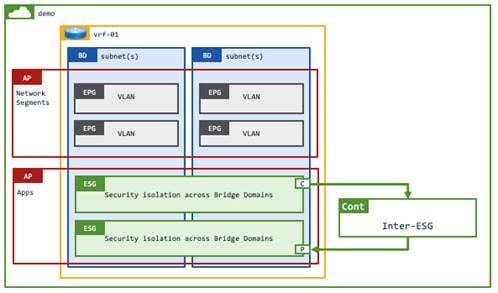
While the use of contracts is equally applicable to both EPGs and ESGs, ESGs provide an enhanced security option as they allow the grouping of endpoints across different bridge domains within a VRF instance (as shown above). Conversely, an EPG is tied to a single bridge domain within a VRF instance therefore it is not possible to select endpoints across different bridge domains. The bridge domain-to-EPG mapping can present a barrier when migrating from a network-centric design to an application-centric design if application endpoints span across different EPGs and bridge domains (Figure 5). ESGs remove this restriction because they operate across a VRF instance.
Design Blueprint–Single ESG per Application
The network infrastructure team at Pseudo Co chose to migrate from their current network-centric design to an application-centric design by creating one security zone per application. The initial design blueprint places all endpoints of a given application into a single ESG. After an application has been mapped to an ESG, the team will evaluate and adjust ESG membership as required. For example, the team might move certain shared services, such as databases, to a dedicated ESG. Moving endpoints between ESGs can be achieved seamlessly without changing the network backing by simply adjusting the ESG selection criteria.
The implementation of a single ESG per application provides network administrators with a clear view of where applications are running on the Cisco ACI fabric, which in turn provides the following key benefits:
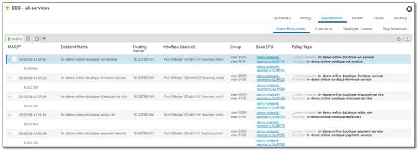
● Improved application visibility: Creation of a single ESG for all application endpoints allows network administrators to understand exactly where the application endpoints are attached to the network. The details included are as follows:
◦ MAC/IP address
◦ Interface
◦ VLAN encapsulation ID
◦ EPG
◦ Policy Tag
◦ VM name (requires read/write VMM integration)
◦ Hosting server (requires read/write VMM integration)
◦ Reporting controller (requires read/write VMM integration)
◦ VM Tag (requires read/write VMM integration)
● Security tied to applications rather than network segments: ESGs allow network and security administrators to implement security based on applications rather than on network segments or IP addresses. This allows for simpler network designs as there is no longer a requirement to insert security devices into the routing path. Instead, Layer 4 to Layer 7 services devices can be dynamically inserted (using service graphs) within an application or between applications.
◦ Increased security through tightening of contracts: Cisco ACI contracts provide stateless Layer 4 hardware-based ACL security controls between applications using provided/consumed contracts, or within a given application using intra-ESG contracts. After an application has been identified and its endpoints mapped into an ESG, you can increase the security of the application by restricting the (filter) ports referenced in the provided contract or by controlling the direction in which TCP connections are established. That is, connections can only be established from consumer to provider.
◦ Isolated application groups: ESGs can be set to "enforced" mode (intra-ESG isolation), which blocks all traffic within the ESG, thus isolating application endpoints. Optionally, you can add an intra-ESG contract to the ESG to permit communication on specific ports within the ESG.
◦ Intelligent service insertion: Layer 4 to Layer 7 services can be dynamically inserted either in front of an application ESG, or within an ESG. For example, an intra-ESG contract with Service Graph can be added to an isolated ESG to redirect all intra endpoint traffic through a Next Generation Firewalls/IPS.
● Application dependency mapping: network administrators are able to leverage an intra-ESG contract to forward all traffic within an ESG, via a service graph, to a Layer 4 to Layer 7 services device such as a firewall. Configuring the firewall with a "permit-any | log" rule allows the firewall to generate syslog messages for all inter-endpoint communication within the ESG. Additionally, traffic destined to the ESG can also be redirected, using a service graph, to a Layer 4 to Layer 7 services device to log all traffic to the application. Note: You can also enable Cisco ACI contract logging. However, the logging is limited to 500pps for denied traffic and 300pps for permitted traffic.
● Improved auditing capabilities: The ability to view application endpoints on the Cisco ACI fabric provides network administrators with a streamlined approach to auditing applications, their associated security rules, and Layer 4 to Layer 7 service integration.
● Improved troubleshooting: The ability to view an application on the Cisco ACI fabric allows network administrators to view the health of individual applications and thus quickly and simply correlate any application performance issues with potential network errors such as packet drops.
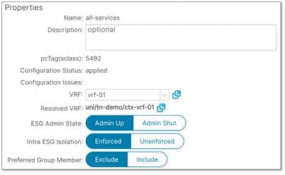
The following graphic details the operational information available in Cisco APIC for a given ESG:
Pseudo Co identified the following steps that are required to convert from a network-centric design to an application-centric design:
1. Implement EPG-to-ESG mapping using an EPG selector to allow open communication between EPGs on a given VRF instance. This removes the requirement of the vzAny contract, allowing for more flexible security options in the future.
2. Implement a single ESG for the online boutique virtual machine endpoints using VM tag identifiers by way of a tag selector.
3. Allow communication using contracts between the online boutique application ESG and other ESGs on the network.
4. Enforce additional security by selecting the protocols and ports that are open to the online boutique application ESG.
As detailed previously, Pseudo Co implemented a simple "permit-any" contract that is provided and consumed on vzAny. During the migration from the network-centric design to the application-centric design, do not change the open security control that is provided by vzAny. Failure to maintain the current open security controls could result in application connectivity issues. At a later stage, Pseduo Co can decide whether the open application security rules defined in the contract are sufficient from a security standpoint. If there is a requirement for tighter security, this can be achieved by only specifying the protocols/ports that are required by the application.
Step 1: Implement a single ESG for open communication between subnets (EPG selectors)
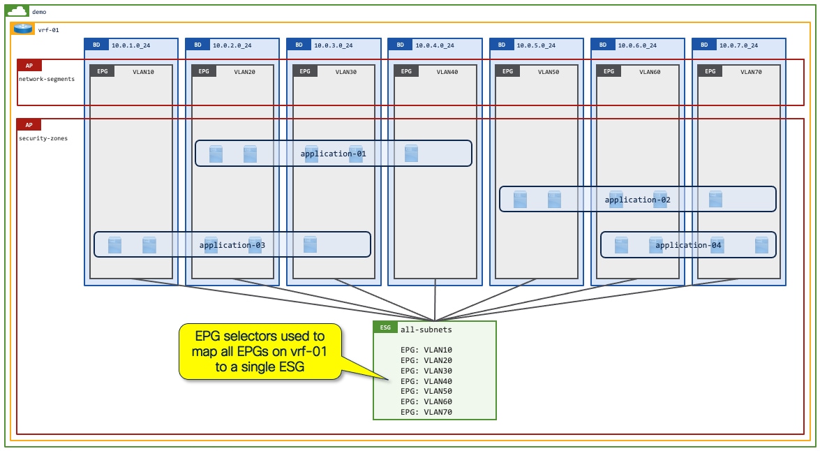
Pseudo Co implemented their Cisco ACI network in a typical network-centric design with a 1:1 mapping between bridge domains and EPGs, as shown in Figure 3. Each bridge domain is configured with a single subnet/default gateway for endpoints and is mapped to a single EPG that provides the VLAN backing. The classification of endpoints into an EPG is performed by matching traffic on an incoming leaf/interface/VLAN.
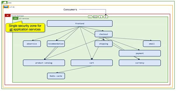
As part of the network-centric to application-centric migration Pseudo Co will implement a single ESG that will provide open communication between all subnets/EPGs. Refer to the following diagram:
The mapping of multiple EPGs to a single ESG using an EPG selector is an alternative solution to allow communication amongst multiple EPGs on a Cisco ACI fabric. EPG-to-ESG mapping is a more flexible solution when compared to using preferred groups. Cisco ACI supports multiple ESGs per VRF instance, whereas there can only be one preferred group per VRF instance. Additionally, you cannot apply a contract to the preferred group itself to allow communication from all EPG members of the preferred group to another EPG outside of the preferred group, whereas you can apply a contract directly to ESGs.
The mapping of multiple EPGs to ESGs is also considered to be a better security design compared to vzAny, as it allows network administrators to select specific EPGs to map rather than using vzAny, which implicitly selects all EPGs, ESGs, and external EPGs within a VRF instance.
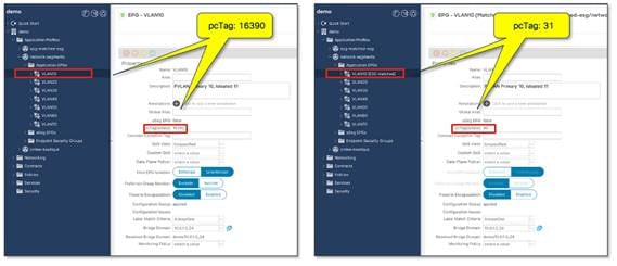
The network administrator should be aware that mapping one or more EPGs to an ESG triggers a change in the class ID of the EPGs. Prior to mapping the EPGs to an ESG, each EPG on a VRF instance will have a unique class ID. When mapping EPGs to an ESG, the class ID of each mapped EPG is rewritten to that of the ESG. Because all endpoints are now classified to an ESG with the same class ID, all traffic is implicitly permitted without a contract.
Note: The reclassification of class IDs causes a momentary drop in network traffic. We recommend that you perform the EPG-to-ESG mapping during a change window.
EPG selectors are also useful for more advanced migration scenarios, such as a Cisco ACI fabric that is deployed already with contracts between EPGs, as opposed to vzAny allowing open communication within the VRF instance. In such a scenario, you must keep those contracts and security groupings while migrating to ESGs from EPGs. Refer to "Endpoint Security Groups > ESG Migration Strategy" in Cisco APIC Security Configuration Guide for detailed steps.
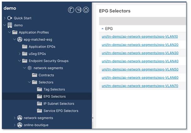
Configure EPG selectors
The figure below shows the configuration. The location is at Tenant > Application Profiles > Application_Profile_name > Endpoint Security Groups > ESG_name > Selectors > EPG Selectors.
Note: Any endpoints in the same VRF instance can belong to the same ESG. However, when configuring ESG with EPG selectors, the EPGs must belong to the same tenant as the ESG.
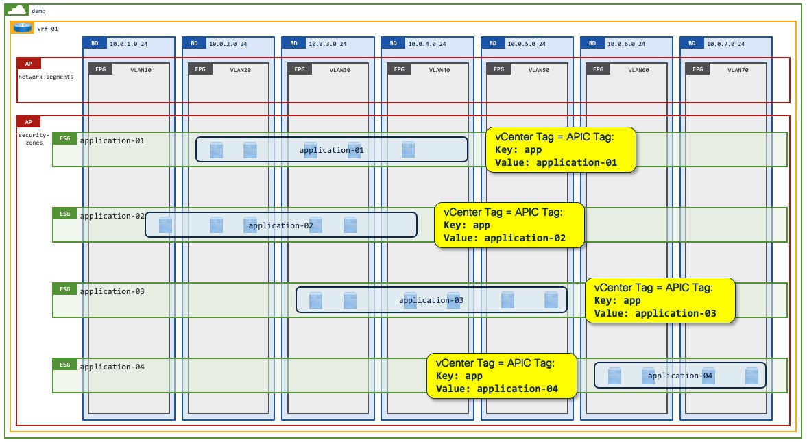
Step 2: Implement a single ESG for all endpoints of a single application (tag selectors)
The application owners at Pseudo Co have assigned tags to their application virtual machines in VMware vCenter to allow for simple identification of the workloads that make up a given application. Cisco ACI can leverage the assigned virtual machine tags by collecting them from VMware vCenter and then mapping them to ESG tag selectors on Cisco APIC.
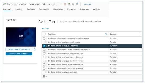
The matching of virtual machine tags in VMware vCenter to Cisco ACI tags in Cisco APIC allows network administrators and application owners to move virtual machines seamlessly and dynamically from their original "all-network-segments" ESG (as shown in Figure 10. ) into the correct "online-boutique:all-services" application ESG. In this step, it is focused on a single application—Online Boutique—but the ability to create multiple ESGs within a VRF instance allows network administrators to contain multiple applications in the same VRF instance with one (or more) ESG per application as shown in Figure 20.
Note: Tag selectors with Virtual Machine tags have a higher priority than EPG selectors. This priority allows the dynamic movement of endpoints between different ESGs on a VRF instance. Full details of selector precedence can be found in the selector precedence order in the FAQ.

Classification based on tag selectors
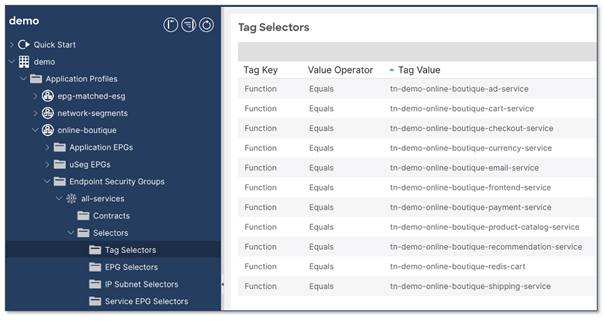
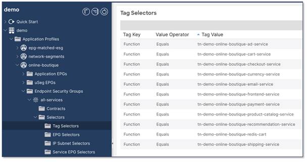
The figure below shows the configuration object for creating tag selectors.
The location is at Tenant > Application Profiles > Application_Profile_name > Endpoint Security Groups > ESG_name > Selectors > Tag Selectors.
The Cisco ACI tag selectors (below) match the virtual machine tags on VMware vCenter where the Function of a virtual machine Equals a specific Tag Value.
For example: Function = tn-demo-online-boutique-currency-service – this key/value pair matches any virtual machines which provide the "currency service" as part of the "online-boutique" application in tenant "demo".
Your configuration must meet the following prerequisites before you can use VM tags for ESG mapping:
● Enable tag collection on the VMM domain.
● Enable micro-segmentation on the EPGs with the VMM domain.
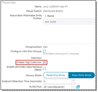
Prerequisite: enable tag collection on the VMM domain
If you use an ESG with VMware tag selector, you must put a check in the "Enable Tag Collection" box for the VMM domain.
The figure below shows the configuration. The location is at Virtual Networking > VMware > Domain name > General.
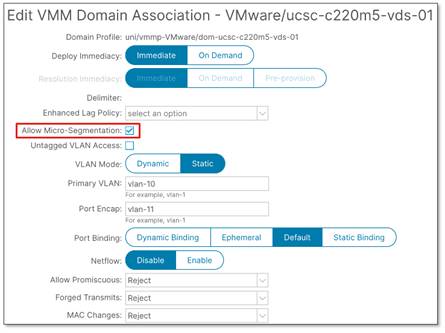
Prerequisite: enable micro segmentation on the EPGs with a VMM domain
If you use an ESG with a VMware vDS VMM domain, you must put a check in the "Allow Micro-Segmentation" box on the EPG associated to the VMM domain to allow endpoints to be selected by the VM tag or VM name. If the EPG is mapped directly to the ESG (EPG selector), there is no requirement to configure "Allow Micro-Segmentation" because the EPG to ESG mapping is based on the EPG VLANs.
Putting a check in the "Allow Micro-Segmentation" box configures a PVLAN (Private VLAN) on the port group for the EPG. When reconfiguring an existing VMM mapped EPG, the vDS is dynamically updated with a new PVLAN pair from the dynamic VLAN pool. If Layer 2 multicast or flooding traffic is required, see the section Example 12: ESG with L2 multicast.
Note: The "Allow Micro-Segmentation" box is not checked by default.
The figure below shows the configuration. The location is at Tenant > Application Profiles > Application_Profile_name > Application EPGs > EPG_name > Domains.
For network deployments where there are intermediary switches (such as blade switches) between the Cisco ACI leaf switch and the ESXi host, the network administrator must statically define the PVLAN pairs that are to be used on the VMM domain. The allocated VLANs must also be configured on the intermediary switch. While PVLAN pairs can be dynamically allocated on Cisco ACI, this may make it difficult for the administrator to configure the same set of PVLAN pairs manually on the intermediary switches. When statically defining the PVLAN pairs on Cisco ACI, the VLAN IDs should be allocated from a static VLAN range in the VLAN pool associated to the VMM domain.
Configure Tag selectors
The next step is to configure an ESG with a tag selector to define which virtual machine endpoints should belong to the ESG.
The figure below shows the configuration. The location is at Tenant > Application Profiles > Application_Profile_name > Endpoint Security Groups > ESG_name > Selectors > Tag Selectors.
The following VMM information is supported:
● VM name (Tag key: __vmm::vmname, Tag value: <VM name>))
● vSphere VM tag (Tag key: <category>, Tag value: <tag name>)
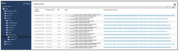
In the example below, the Cisco APIC pulled the VM names (vmm::vmname) and vSphere VM Tags from VMware vCenter. The Cisco APIC then assigned them to the MAC address of the VM. The Cisco APIC has then matched the vSphere tags to the Cisco APIC tag selectors. The bridge domain and VRF instance are identified from the Cisco APIC endpoint mapping database.
Note: Cisco APIC reads tags from VMware vCenter once per 5-minute time window
The location in the Cisco APIC GUI is at Tenant > Policies > Endpoint Tags > Endpoint MAC.
Step 3: Communication between applications (contract between ESGs)
After the endpoints of an application have been grouped into a single ESG, you must provide access to the application (using contracts) from the wider network.
In the example below, the online boutique application (online-boutique:all-services ESG) provides a service (contract provider) which is consumed by the application-monitoring:all-services ESG, the all-network-segments ESG, and the remote-users external EPG from any remote subnet using the "permit-to-tn-demo-online-boutique" contract.
The online-boutique:all-services ESG also consumes services such as Active Directory, DNS, NTP, and software updates from the core-services:all-services ESG.
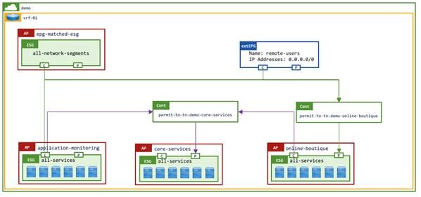
The arrows indicate the expected traffic flow, which is from the consumer to the provider.
Table 1. Contract relationship
| Consumer ESGs |
Contract Name |
Provider ESGs |
| epg-matched-esg:all-network-segments |
permit-tn-demo-online-boutique |
online-boutique:all-services |
| application-monitoring:all-services |
permit-tn-demo-online-boutique |
online-boutique:all-services |
| extEPG:remote-users |
permit-tn-demo-online-boutique |
online-boutique:all-services |
| online-boutique:all-services |
permit-tn-demo-core-services |
core-services:all-services |
| application-monitoring:all-services |
permit-tn-demo-core-services |
core-services:all-services |
By configuring contracts between ESGs, only specific inter-ESG traffic is allowed. In addition, intra-ESG traffic is permitted by default. Instead of using a "default" permit-any filter, you can use more granular filters to allow specific types of traffic only for the inter-ESG traffic. For more information, see the ACI Contract Guide.
Step 4: Enforce additional application security
Intra-ESG isolation or contract
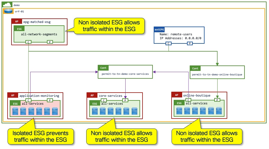
While communication within an ESG is "permit-all" by default, additional security enforcement can be applied to the ESG to either "deny-all" traffic or "permit-specific-ports" within the ESG. To "deny-all" traffic, the ESG simply needs to have Intra-ESG Isolation set to enforced. To "permit-specific-ports" an intra-ESG contract needs to be added to the ESG. The intra-ESG contract could leverage a service graph to redirect traffic to a Layer 4 to Layer 7 services device such as a next generation firewall/IPS.
In the example below, all endpoints in the online-boutique:all-services ESG are able to communicate freely. However, communication between the endpoints in the application-monitoring:all-services ESG is blocked as there is no requirement for inter-endpoint communication between the monitoring servers.
The figure below shows intra-ESG isolation configuration. By default, intra-ESG isolation is unenforced. The location is at Tenant > Application Profiles > Application_Profile_name > Endpoint Security Groups > ESG_name > Policy > General.
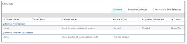
The figure below shows the intra-ESG contract configuration. The location is at Tenant > Application Profiles > Application_Profile_name > Endpoint Security Groups > ESG_name > Contracts > Add Intra-ESG Contract.
Service Graph with PBR for Layer 4 to Layer 7 service insertion
In addition to the hardware-based permit/deny security enforcement using contracts with stateless filtering, you can also dynamically insert stateful Layer 4 to Layer 7 devices such as firewalls and IPS (Intrusion Prevention Systems) into the data path, either between ESGs or within ESGs (intra-ESG). 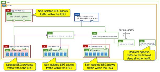
For more information, see the ACI Contract Guide and Cisco ACI Policy-Based Redirect Service Graph Design White Paper.
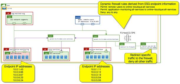
You must consider the Layer 4 to Layer 7 services device configuration when redirecting traffic to the Layer 4 to Layer 7 services device. In the example below, the flexible nature of ESGs allows the logical grouping of endpoints from different subnets into discrete security zones. The configuration on the firewall needs to reflect the IP address information derived from the ESGs. This can be achieved by the firewall management platform pulling ESG membership information.
The following applications and plug-ins are currently available for ESG membership advertisement:
● Cisco Adaptive Security Appliance (ASA) and Cisco Firepower Threat Defense (FTD): ACI Endpoint Update
● Check Point CloudGuard: CloudGuard for ACI
● Fortinet Fabric Connectors: Cisco ACI SDN connector
● Palo Alto Networks Panorama: Panorama Plugin for Cisco ACI (Roadmap)
If your Layer 4 to Layer 7 services device is different from those listed above, endpoints to ESG membership information can be retrieved using the Cisco APIC API. Thus, a simple script or application could be used to retrieve the information and create equivalent security groups on the Layer 4 to Layer 7 services device. For more information, see the FAQ.
This chapter shows ESG use cases with many individual examples so that you can directly jump to the use cases of interest (Table 2 and Table 3). If you are new to ESGs or prefer a walkthrough of a scenario-based example, read the chapter Network Centric to Application Centric Migration Story: Pseudo Co.
The ESGs present network administrators with many flexible design options for segmenting physical or virtual workloads as detailed in the Detailed Design Examples section. In addition to the option of creating fine-grained, application-focused ESGs, Cisco ACI also allows network administrators to use ESGs to aggregate multiple EPGs (VLANs) or create subnet-based security zones within a VRF instance. Both options are equally flexible and you can use them concurrently. Indeed, a powerful benefit of ESGs is the ability to move endpoints dynamically from a zone-based security environment to an application-based security environment without modifying the network backing.
Flexible Security Zones with ESGs
1. Single security zone per VRF instance: Map all EPGs within a VRF instance to a single ESG as a default security zone for all endpoints.
2. Multiple Security zones per VRF instance: Map a subset of EPGs to an ESG security zone. Create one or more ESG security zones per VRF instance.
3. Security zones per application: Map individual endpoints to an ESG via Tag selectors across any subnet or VLAN on a given VRF instance.
We recommend that you use options 1 or 2 as the base configuration so that all endpoints are covered by an ESG in one way or the other, and then use option 3 for more granular segmentation groups. The following diagrams depict each option when deployed individually. To combine different types of selectors, refer to the selector precedence order in the FAQ.
The following figure is explained in more detail in Example 1: A security zone per VRF as a default zone (EPG selectors) along with Figure 29.
The following figure is explained in more detail in Example 2: A security zone per set of subnets/VLANs (EPG Selectors) along with Figure 30.
The figure below shows application endpoints selected by VMware vCenter/Cisco APIC tags. Additional examples, such as Figure 31, are shown in detail in the next section.
The table below summarizes several different ESG examples such that the reader can understand how the different selector options can be used. You can use all options simultaneously as desired and as shown in the table below.
Note: If you require Layer 2 multicast within the ESGs, the selectors should be EPG selectors or tag selectors with MAC addresses. See Example 12 for more information.
Table 2. Examples of ESG deployment options – single selector criteria
| Category |
Example |
Description |
| Base Security with EPG selectors |
Example 1: A security zone per VRF instance as a default zone (EPG selectors) |
Map all EPGs to a single ESG as a default security zone of a given VRF instance. |
| Example 2: A security zone per set of subnets/VLANs (EPG Selectors) (Multiple security zones per VRF instance) |
Map a subset of EPGs to an ESG security zone. Create one of more ESG security zones per VRF instance. |
|
| Granular Security with Tag selectors
Map individual endpoints across any subnets or VLANs to an ESG as a granular security group via VMware tags or Cisco APIC policy tags |
VMware VM tags are pulled from VMware vCenter via VMM integration. |
|
| Example 4: Tag selectors without VMM integration for VM endpoints using the MAC address |
Cisco ACI administrators assign a Cisco APIC policy tag to MAC addresses of each virtual machine endpoint on Cisco APIC. No tag sync with VMware vCenter. |
|
| Example 5: Tag selectors without VMM integration for VM endpoints using the IP address |
Cisco ACI administrators assign a Cisco APIC policy tag to IP addresses of each virtual machine endpoint on Cisco APIC. No tag sync with VMware vCenter. |
|
| Example 6: Tag selectors for bare metal endpoints using the MAC address |
Cisco ACI administrators assign a Cisco APIC policy tag to MAC addresses of each bare metal endpoint on Cisco APIC. |
|
| Example 7: Tag selectors for bare metal endpoints using the IP address |
Cisco ACI administrators assign a Cisco APIC policy tag to IP addresses of each bare metal endpoint on Cisco APIC. |
|
| PVLAN is required on the intermediary non-Cisco ACI switches. |
||
| Granular Security with IP Subnet selectors |
Assign IP addresses or subnets directly to an ESG. |
The following table shows additional examples with multiple selectors used in conjunction with each other:
Table 3. Examples of ESG deployment options – multiple selector criteria
| Example |
Description |
| An example from chapter Network Centric to Application Centric Migration Story: Pseudo Co. |
|
| Example 11: Multiple security zones via EPG selectors with a quarantine ESG via Tag selectors. |
Assign a tag to endpoints that are malfunctioning or vulnerable to isolate them from each security zone. |
| An example of how to design ESGs for situations where there is L2 multicast/flood traffic. |
|
| An example of how to configure proxy ARP for IP-based selectors when the EPGs are matched to an ESG using EPG selectors. |
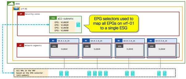
Example 1: A security zone per VRF instance as a default zone (EPG selectors)
Many customers start their Cisco ACI deployments with a permit-all contract provided and consumed on vzAny, or alternatively including all EPGs in a preferred group to allow all communication within a VRF instance, with the aim of gradually implementing more security later. An ESG can simplify this approach by allowing network administrators to have a simple, flexible starting point with a better extensibility for the future. By mapping all EPGs in the VRF instance to a single ESG using EPG selectors, the ESG acts as a default security zone. After you create this base security zone, you can explicitly select endpoints to be classified to other more granular ESGs.
An ESG as a default security zone acts as a fallback for all endpoints in the VRF instance by mapping all EPGs in the VRF instance to an ESG using EPG selectors. All endpoints shown below can talk to each other as they belong to the same ESG. A network administrator could implement an intra-ESG contract with a service graph PBR such that (by default) all intra-ESG traffic is redirected to a firewall. Alternatively, you can configure the default security zone ESG with isolation enforced, preventing intra-ESG communication until the workloads are moved to their correct application ESG with their associated contracts.
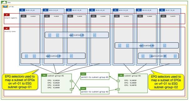
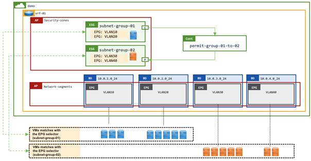
Example 2: A security zone per set of subnets/VLANs (EPG Selectors)
Instead of creating a single default security zone for a given VRF instance as shown in the previous example, an ESG with EPG selectors can easily create multiple security zones within the same VRF instance without each zone being limited to one bridge domain. In this use case, each ESG represents one enclave, such as organization or development group, based on an organization’s security requirements. This allows communications within each enclave without additional configuration while, by default, blocking cross-enclave communications. Each enclave likely contains multiple applications that consist of a set of endpoints across bridge domains. You cannot achieve this design using EPGs, as the endpoints are located across multiple bridge domains.
In this example, each enclave is assigned a set of dedicated VLANs/subnets, such as VLAN 10 and 20 for ESG subnet-group-01 and VLAN 30 and 40 for ESG subnet-group-02. In this situation, the network administrator can easily create an ESG for each enclave using EPG selectors.
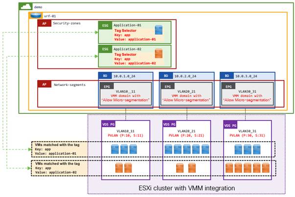
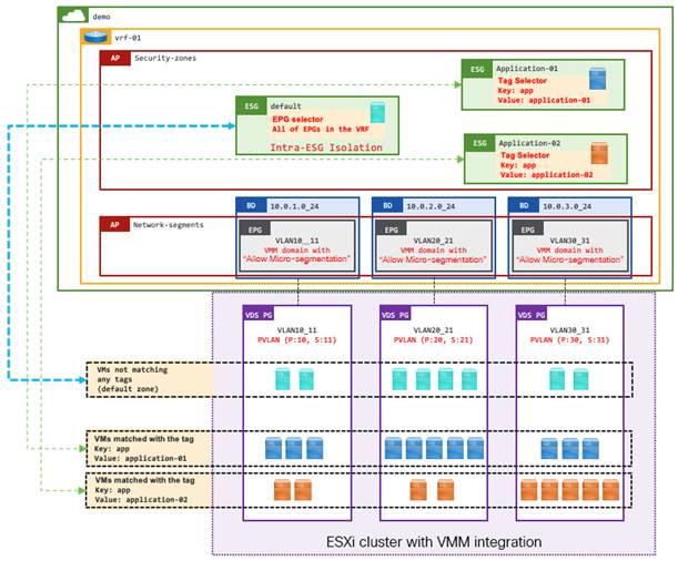
Example 3: Tag Selectors with VMM integration
This is an example of ESG tag selectors matching VM tags or VM names from VMware vCenter. For this use case, VMM domain integration with read-write permissions is required, as opposed to read-only. Although Cisco APIC with read-only integration retrieves VM names and tags from VMware vCenter, such data is not associated to tenant objects such as EPGs or ESGs. Thus, you currently cannot leverage those for ESG selectors.
When VM tags or VM names are used for tag selectors, the following two configurations are required on top of the tag selectors themselves.
● Enable "Tag Collection" under the VMM domain itself.
● Enable "Allow Micro-Segmentation" through the VMM domain association in the EPG.
◦ This deploys PVLAN on Cisco ACI leaf switches and VMware vCenter port groups automatically. This is to prevent VMware virtual switches from bridging the traffic within the same port group without forwarding the traffic to Cisco ACI.
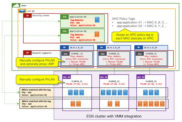
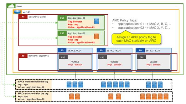
Example 4: Tag selectors without VMM integration for VM endpoints using the MAC address
This example shows ESG tag selectors matching VM endpoints using the MAC address. This option is applicable to those customers who have ESX clusters without read-write VMM integration.
You can connect the VM endpoints on VMware vCenter to a Cisco ACI fabric through a "physical" domain without vCenter VMM integration. If you are using physical domains for VMware vCenter, you can optionally have read-only VMM integration such that the Cisco APIC can have visibility of the VM endpoints attachment. However, you cannot use VM tags or VM names on VMware vCenter for ESG classification without read-write VMM integration.
In the following example, the following three configuration option are required on top of tag selectors themselves:
● Manually create and assign a Cisco APIC policy tag to each MAC address on the Cisco APIC.
● Manually configure PVLAN on both Cisco ACI EPGs (VLANs) and port groups in VMware vCenter.
◦ This prevents VMware virtual switches from bridging the traffic within the same port group without forwarding the traffic to Cisco ACI.
● (Optional) Enable proxy ARP on the EPGs.
◦ When PVLAN is enabled, flooding or layer 2 multicast traffic is blocked within each EPG as well as between EPGs with PVLAN. This results in ARP not being resolved between endpoints in those EPGs, proxy ARP resolves this limitation by Cisco ACI leaf switches responding to the ARP requests on behalf of the target endpoint. Note that communication between endpoints in different subnets do not need proxy ARP because ARP requests to the Cisco ACI bridge domain SVI, which should be the default gateway, is not blocked by PVLAN.
Configure PVLAN on Cisco ACI EPGs with physical domains manually using static ports (static path binding). PVLAN on Cisco ACI EPGs requires one of the following configurations as well:
● Enable Intra-EPG isolation
● Configure Intra-EPG contract
You can also enable proxy ARP along with the following options:
● Enable Intra-EPG isolation, then explicitly enable proxy ARP
● Configure Intra-EPG contract, then proxy ARP is implicitly enabled
In this example, the first option (Intra-EPG isolation with proxy ARP) is used.
Note: To streamline the integration process, network administrators can use automation tools such as Ansible, Terraform, or python to read the virtual machine MAC addresses from VMware vCenter and then create the MAC tags in the Cisco APIC. Automation could also be used to create both the EPG/VLAN static bindings in the Cisco APIC, and the PVLAN port groups in VMware vCenter.
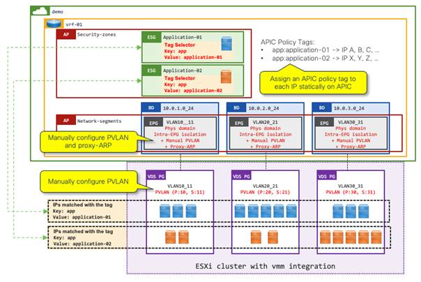
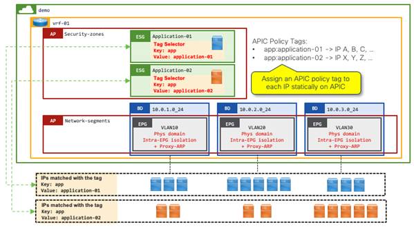
Example 5: Tag selectors without VMM integration for VM endpoints using the IP address
This example shows ESG tag selectors matching VM endpoints via IP address. This option is applicable to those customers who have ESX clusters without Read-Write VMM integration.
The VM endpoints on VMware vCenter can be connected to a Cisco ACI fabric through a "physical" domain without vCenter VMM integration. Customers using physical domains for VMware vCenter may optionally have read-only VMM integration such that the Cisco APIC can have visibility of VM endpoints attachment. However, VM tags or VM names on VMware vCenter cannot be used for ESG classification without read-write VMM integration.
In this example, the following three configuration options are required in addition to the tag selectors:
● Manually create and assign a Cisco APIC policy tag to each IP address on the Cisco APIC.
● Manually configure PVLAN on both Cisco ACI EPGs (VLANs) and port groups in VMware vCenter.
◦ This is to prevent VMware virtual switches from bridging the traffic within the same port group without forwarding the traffic to Cisco ACI.
● Enable proxy ARP on the EPGs.
◦ For Cisco ACI switches to apply ESG security based on IP addresses, traffic must be routed instead of bridged. To ensure all traffic is handled as routed traffic, you must enable proxy ARP on the EPGs.
◦ When PVLAN is enabled, flooding or Layer 2 multicast traffic is blocked within each EPG as well as between EPGs with PVLAN. This results in ARP not being resolved between endpoints in those EPGs, Proxy ARP resolves this limitation by the Cisco ACI leaf switches responding to the ARP requests on behalf of the target endpoint.
This example is very similar to Example 4: Tag Selectors without VMM integration for VM endpoints via MAC address, except for the first point (IP address instead of MAC address) and the third point (proxy ARP is mandatory).
Configure PVLAN on Cisco ACI EPGs with physical domains manually using static ports (static path binding). PVLAN on Cisco ACI EPGs requires one of the following configurations as well:
● Enable intra-EPG isolation
● Configure intra-EPG contract
Proxy ARP can also be enabled along with the following options:
● Enable intra-EPG isolation, then explicitly enable proxy ARP
● Configure intra-EPG contract, then proxy ARP is implicitly enabled
This example uses the first option (intra-EPG isolation and proxy ARP).
Note: To streamline the integration process, network administrators can use automation tools such as Ansible, Terraform, or python to read the virtual machine IP addresses from VMware vCenter and then create the IP tags in the Cisco APIC. You can also use automation to create both the EPG/VLAN static bindings in the Cisco APIC and the PVLAN port groups in VMware vCenter.
Example 6: Tag selectors for bare metal endpoints using the MAC address
This example shows ESG tag selectors matching bare metal endpoints through a Cisco ACI policy tag statically attached to each endpoint MAC address.
This is identical to Example 4: Tag selectors without VMM integration for VM endpoints via MAC address with the exception of not configuring the vDS. The PVLAN configuration is also not required on the EPG because there are no intermediary switches such as blade or virtual switches. If there are non-Cisco ACI switches between the endpoints and Cisco ACI switches, PVLANs are still required. See Example 8: Tag selectors with intermediary switches for an example use case.
Example 7: Tag selectors for bare metal endpoints using the IP address
This example shows ESG tag selectors matching bare metal endpoints through a Cisco ACI policy tag attached to each endpoint IP address.
This is identical to Example 5: "Tag selectors without VMM integration for VM endpoints via IP address" with the exception of not configuring the vDS. The PVLAN configuration is also not required on the EPG because there are no intermediary switches such as blade switches. If there are non-Cisco ACI switches between the endpoints and Cisco ACI switches, PVLANs are still required. See Example 8: "Tag selectors with intermediary switches" for an example use case.
Note: Proxy ARP is still required, as this example is using the IP address as the selection criteria.
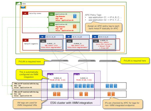
Example 8: Tag selectors with intermediary switches
This is an example where there are intermediary switches between Cisco ACI leaf switches and endpoints. In the case of VM endpoints, those may be behind blade switches such as Cisco UCS Fabric Interconnect or virtual switches from any virtualization solution.
In such a case, PVLANs need to be extended from the Cisco ACI leaf switch through the intermediary switches to the vDS port groups on the virtual switches. This is to ensure that those switches do not bridge the traffic based on VLANs before it reaches a Cisco ACI leaf switch where ESG security is applied.
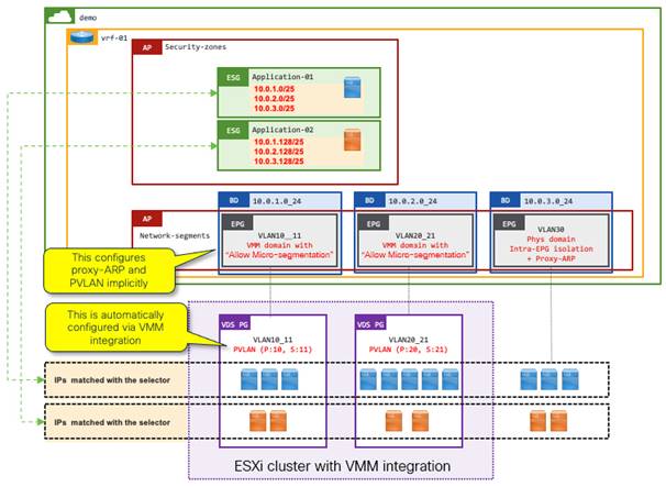
Example 9: IP subnet selectors
This is an example of how to specify IP addresses or subnets directly under an ESG without a tag. This is useful when all IP addresses within a specific range should belong to the same ESG.
Because this uses the IP address as the criteria, the proxy ARP requirement mentioned in other IP address examples is also applicable here. Because of that, if all endpoints in a bridge domain subnet or multiple bridge domain subnets should belong to the same ESG, we recommend that you use EPG selectors to match all EPGs in the bridge domains instead. However, EPG selectors are not supported when the EPGs and the ESG belong to different tenants, such as when the EPGs belong to tenant common while the ESG belongs to a user tenant. In such a case, you can still use IP subnet selectors.
In this example, IP subnet selectors are used to classify one half of each bridge domain subnet into one ESG and the other half to another ESG, regardless if the endpoints are VMM-integrated or bare metal. For VM endpoints, due to the intermediary virtual switches, PVLAN is required on the port groups. In this example, the "Allow Micro-segmentation" option with VMM integration is used to achieve that. "Allow Micro-Segmentation" also implicitly enables proxy ARP.
Example 10: ESG as a container of an application using tag selectors with a default security zone using EPG selectors
The following example uses different types of selectors together:
● A security zone per VRF instance (EPG selectors) – A default security zone for the VRF instance as a catch-all group with intra-ESG isolation so that by default no endpoints can talk to each other
● A security zone per application (tag selectors with VMM integration) - To pull endpoints from the default security zone so that they can talk to the others in the same group or another group using contracts.
This is equivalent to an example from the Network Centric to Application Centric Migration Story: Pseudo Co. chapter.
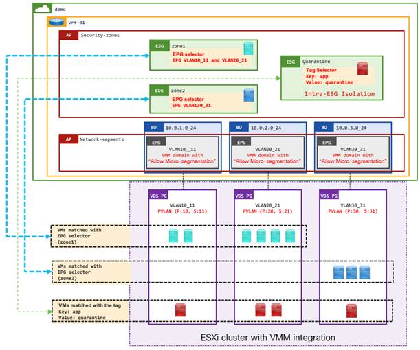
Example 11: Multiple security zones using EPG selectors with a quarantine ESG using tag selectors.
The following example uses different types of selectors together:
● A security zone per subnets/VLANs (EPG selectors) – As base security zones per enclave that consist of a set of subnets or VLANs that are represented by EPGs. Endpoints in each zone (ESG) can talk to each other by default. Communication across each zone is explicitly allowed using contracts.
● A quarantine security zone (Tag selectors with VMM integration) - To pull malicious endpoints from each security zone to quarantine them. A quarantine zone is configured with intra-ESG isolation to block all traffic inside the zone (ESG).
This is using the same set of selectors (EPG and Tag) as Example 10: ESG as a container of application via Tag selectors with a default security zone via EPG selectors, but in the opposite way. In this example, by default, endpoints belong to a respective security zone (ESG) with appropriate security settings based on the network distribution (subnets/VLANs) while tags are used to revoke security policies allowing communications from certain endpoints.
Example 12: ESG with Layer 2 multicast
When Layer 2 multicast is required for endpoint communication within an ESG, such as cluster keepalive or multicast DNS, the configuration options shown below interfere with the requirements, as those options block flooding and Layer 2 multicast traffic.
● Intra-EPG isolation
● Intra-EPG contract
● "Allow Micro-Segmentation" with a VMM domain
Note: Intra-EPG isolation/contract blocks flooding and Layer 2 multicast traffic between EPGs and within EPGs that have these settings. However, with "Allow Micro-Segmentation," the scope of impact is VLANs instead of the entire EPG.
This means that selectors that require these configurations cannot be used in such a situation.
Selectors that can be used for Layer 2 multicast, in other words selectors that do not need any of the above configurations, are:
● EPG selectors
● Tag selectors with MAC addresses
The details of each selector are explained below.
EPG Selectors
These selectors do not require any of the configuration options mentioned above that interfere with Layer 2 multicast forwarding.
Refer to Example 1 or Example 2.
Tag Selectors with MAC Address
These selectors can meet the requirement of Layer 2 multicast when a PVLAN is not required. That is, when there are no intermediary switches in between the leaf switch and the endpoint.
Refer to Example 6: Tag Selectors for bare metal endpoints via MAC address.
Tag Selectors with VM Tags or VM Names
These selectors cannot be used because these require "Allow Micro-Segmentation" with a VMM domain.
IP-based Selectors Such as IP Subnet Selectors or Tag Selectors with an IP Address
These selectors cannot be used because these require proxy ARP on the EPGs, which is configured using intra-EPG isolation, intra-EPG contracts or "Allow Micro-Segmentation" with a VMM domain.
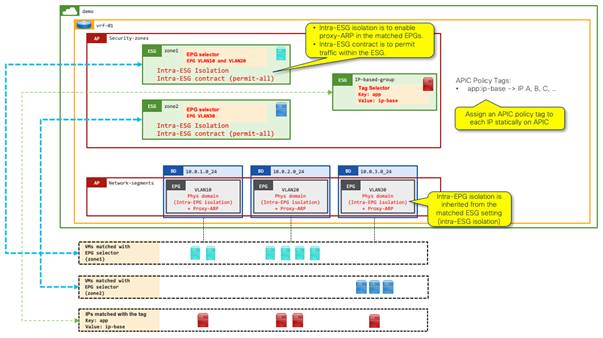
Example 13: EPG Selectors and IP-based Selectors Without a VMM Domain
As shown in the following examples, proxy ARP is required when using IP addresses as the criteria for selectors:
● Example 5: Tag selectors without VMM integration for VM endpoints via IP address
● Example 7: Tag Selectors for bare metal endpoints via IP address
● Example 9: IP Subnet Selectors
To enable proxy ARP, example 5 listed the following options:
● Enable intra-EPG isolation, then enable proxy ARP
● Configure intra-EPG contract, then proxy ARP is implicitly enabled
Note: In addition to the two options above, "Allow Micro-Segmentation" for VMM integration also enables proxy ARP implicitly for the VLANs deployed for the VMM integration. In such a case, the consideration mentioned below in this example is not applicable.
There is a consideration with these two options when EPG selectors are used because when EPGs are matched to an ESG, all security configurations including these two must be performed using the ESG instead of individual EPGs. This emanates from the philosophy of the ESG: decouple network and security to keep configuration and design easy to understand and maintain. The problem is when intra-ESG isolation is enabled in the ESG, all traffic within the ESG is blocked even though users can now enable proxy ARP under the matched EPGs. On the other hand, intra-ESG contract in the ESG enforces contract rules on traffic within the same ESG, but proxy ARP is not enabled under the hood unlike intra-EPG contract.
To overcome these problems, the following configuration options should be applied when both EPG selectors and IP-based selectors are used simultaneously.
1. Enable intra-EPG isolation and proxy ARP on the EPGs.
2. Enable intra-ESG isolation on the ESG.
a. This ensures that the EPG configuration in Step 1 is not overridden by the ESG in Step 4.
3. Enable an intra-ESG contract with permit all, such as the default filter on the ESG.
a. This allows open communication within the ESG, which is blocked otherwise by Step 2.
4. Match the EPGs to the ESG using EPG selectors.
The following figure illustrates this example with these configuration options:
Appendix: Cisco ACI Tenant Design Examples Using ESGs
This appendix explains the options to distribute Cisco ACI components (VRF instance/bridge domain/EPG/ESG) across tenants for a given VRF instance. It is primarily focused on when ESGs are used for security, but most of the concepts are applicable regardless of the ESGs.
The table below summarizes the Cisco ACI tenant design examples in this section. The following subsections explain each example in detail.
Table 4. Cisco ACI tenant Design Examples
| Category |
Examples |
Tenant Design |
| Network and security distributions across tenants |
Example 1: All are in a user tenant |
A VRF instance, bridge domains, EPGs and ESGs are in a user tenant |
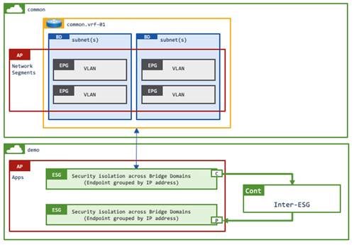
| Example 2: VRF instance/bridge domains/EPGs (VLANs) are in tenant common while ESGs are in user tenants |
Strict separation between network and security. All network - a VRF instance, bridge domains, and EPGs (VLANs) are in tenant common Security - ESGs are in user tenants |
|
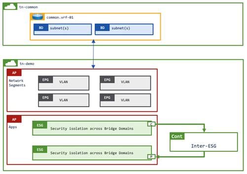
| Example 3: VRF instance/bridge domains are in tenant common while EPGs (VLANs) and ESGs are in user tenants |
Loose separation between network and security. Basic network - a VRF instance, bridge domains are in tenant common EPGs (VLANs) and ESGs (security) are in user tenants |
|
| Shared services across tenants |
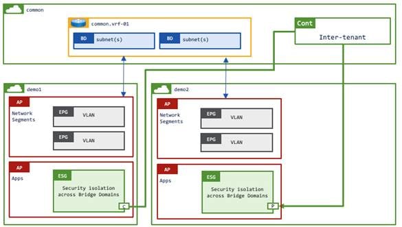
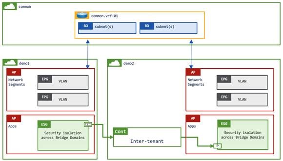
Example 4: Shared services are in the same VRF instance from tenant common |
This is applicable when the same VRF instance in tenant common is shared across multiple user tenants A VRF instance and bridge domains are in common tenant EPGs and ESGs are in user tenant2 |
| Example 5: Shared services are in a different VRF instance |
Regardless of the network and security distributions across tenants, deploy shared services in its own dedicated VRF instance and configure explicit VRF instance route leaking to provide connectivity. A VRF instance, bridge domains, EPGs and ESGs are in user tenant1 A VRF instance and an L3Out are in user tenant2 |
The following table summarizes the supported ESG selectors for each tenant design option:
Table 5. Cisco ACI tenant design options and supported ESG selectors
| VRF |
Bridge Domain |
EPG |
ESG |
Supported Selectors |
| Tenant common |
Tenant common |
Tenant common |
Tenant common |
Tag Selector (Ep MAC) Tag Selector (Ep IP) Tag Selector (BD Subnet) Tag Selector (Static Endpoint) Tag Selector (VM name) Tag Selector (VM Tag) IP Subnet Selector EPG Selector |
| Tenant common |
Tenant common |
Tenant common |
User Tenant |
Tag Selector (Ep MAC)1 Tag Selector (Ep IP)1 IP Subnet Selector |
| Tenant common |
Tenant common |
User Tenant |
User Tenant |
Tag Selector (Ep MAC) Tag Selector (Ep IP) Tag Selector (Static Endpoint) Tag Selector (VM name) Tag Selector (VM Tag) IP Subnet Selector EPG Selector |
| Tenant common |
User Tenant |
User Tenant |
User Tenant |
Tag Selector (Ep MAC) Tag Selector (Ep IP) Tag Selector (BD Subnet) Tag Selector (Static Endpoint) Tag Selector (VM name) Tag Selector (VM Tag) IP Subnet Selector EPG Selector |
| User Tenant |
User Tenant |
User Tenant |
User Tenant |
Tag Selector (Ep MAC) Tag Selector (Ep IP) Tag Selector (BD Subnet) Tag Selector (Static Endpoint) Tag Selector (VM name) Tag Selector (VM Tag) IP Subnet Selector EPG Selector |
Footnote 1: Policy Tags in the user tenant can be assigned to the MAC or IP address in tenant common by specifying the name of the bridge domain or VRF instance in tenant common. However, if the user tenant has a bridge domain or VRF instance with the same name, the policy tag is assigned to the MAC or IP address in the bridge domain or VRF instance in the user tenant.
Example 1: All in a user tenant
This example is one of the most common use cases, where all of objects: a VRF instance, bridge domains, EPGs and ESGs are in a user tenant. Contracts between ESGs are also in the same user tenant.
Example 2: VRF instance/bridge domains/EPGs (VLANs) in tenant common while ESGs in user tenants
This example has ESGs in a user tenant whereas the VRF instance, the bridge domains and the EPGs are in the common tenant. Contracts between ESGs are defined in the same user tenant.
An EPG selector cannot be used in this example because the EPGs must belong to the same tenant as the ESG for EPG selector.
Example 3: VRF instance/bridge domains are in tenant common while EPGs (VLANs) and ESGs are in user tenants
This example has EPGs and ESGs in a user tenant whereas the VRF instance and the bridge domains are in the common tenant. Contracts between ESGs are defined in the same user tenant.
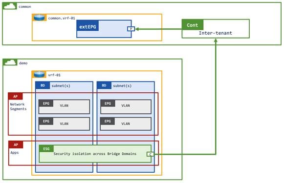
Example 4: Shared services in the same VRF instance from tenant common
This example has EPGs and ESGs in each of the user tenants whereas the VRF instance and the bridge domains are in the common tenant. Although this example uses an inter-tenant contract, this example still allows intra-VRF instance communication by using a VRF instance in the common tenant. Thus, there is no need to configure route leaking. Inter-tenant intra-VRF instance contracts between ESGs must be defined in either the common or provider tenant. If the contract is defined in the provider tenant, the contract must be exported to the consumer tenant (Figure 45).
Example 5 Shared services in a different VRF instance
This example has an L3Out in tenant common or a user tenant that has an inter-tenant inter-VRF instance contract with another user tenant that has a VRF instance, bridge domains, EPGs, and ESGs. Inter-tenant inter-VRF instance contracts between the L3Out external EPG and ESGs need to be defined in either the common or provider tenant. If the contract is defined in the provider tenant, the contract must be exported to the consumer tenant (Figure 47).
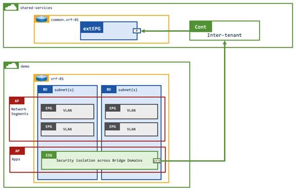
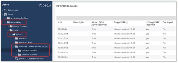
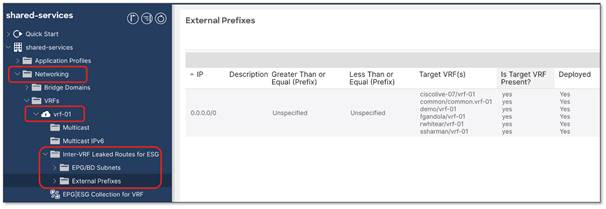
Inter-VRF instance route-leaking is required for this example.
The location is at Tenant > Networking > VRFs > VRF_name > Inter-VRF Leaked Routes for ESG.
This section covers frequently asked questions.
Refer to the following documents for details of ESGs and contracts:
● "Endpoint Security Groups > Contracts" in the Cisco APIC Security Configuration Guide
● "Endpoint Security Groups > ESG Migration Strategy" in the Cisco APIC Security Configuration Guide
EPG Selector – Cisco APIC release 5.2(1)
Tag Selector - Cisco APIC release 5.2(1)
IP Subnet Selector - Cisco APIC release 5.0(1)
See "Endpoint Security Groups > Selectors" In the Cisco APIC Security Configuration Guide as well.
Table 6. Precedence for switched traffic
| Precedence |
Selector |
| 1 |
Tag Selector (Endpoint MAC Tag) Tag Selector (Static Endpoint) |
| 2 |
Tag Selector (VMM Endpoint MAC Tag) |
| 3 |
EPG Selector |
Table 7. Precedence for routed traffic
| Precedence |
Selector |
| 1 |
Tag Selector (Endpoint IP Tag) IP Subnet Selector (host IP) |
| 2 |
Tag Selector (BD subnet) IP Subnet Selector (subnet) |
| 3 |
Tag Selector (Endpoint MAC Tag) Tag Selector (Static Endpoint) |
| 4 |
Tag Selector (VMM Endpoint MAC Tag) |
| 5 |
EPG Selector |
● In a read/write VMM domain (default option) the network admin simply maps an EPG to a VMM domain. The network controller (Cisco APIC) selects an unused VLAN from a VLAN pool, adds the VLAN to all host facing ports, and configures a port group on the VMware vDS with the EPG name and the correct VLAN ID through VMware vCenter’s public API in the same way that Ansible/Terraform does. This approach mitigates the risk of VLAN mismatches between the physical network and the vDS.
ESG tag selectors with VM tags or VM names from VMware vCenter can be used only in this mode.
● In a read-only VMM domain the configuration in Cisco APIC does not get propagated to VMware vCenter to keep a clear configuration domain separation whilst still providing the network admin on Cisco APIC the visibility of the port groups, VLANs and VMs on the VMware vCenter. In this mode, the network admin configures an EPG with a given VLAN ID on all host facing ports, the network admin then informs the VMware vCenter admin of the VLAN ID such that the admin can create a port group on the vDS with the same VLAN ID.
The following API query retrieves all endpoints and associated IP addresses from a specific ESG:
https://{{apic}}/api/mo/uni/tn-{{tenantName}}/ap-{{appProfileName}}/esg-{{esgName}}.json?query-target=subtree&target-subtree-class=fvCEp&rsp-subtree=children&rsp-subtree-class=fvIp
The Cisco APIC response includes each endpoint connected to the ESG, and (where available) the endpoint IP address:
"fvCEp": {
"attributes": {
"annotation": "",
"baseEpgDn": "uni/tn-demo/ap-network-segments/epg-192.168.52.x_24",
"bdDn": "uni/tn-demo/BD-192.168.52.x_24",
"childAction": "deleteNonPresent",
"contName": "email-service",
"dn": "uni/tn-demo/ap-online-boutique-hx/esg-all-services/cep-00:50:56:A1:81:D3",
"encap": "vlan-1206",
"esgUsegDn": "",
"extMngdBy": "",
"fabricPathDn": "topology/pod-1/paths-102/pathep-[hx-dev-01-fi-b]",
"hostingServer": "10.237.98.148",
"id": "0",
"idepdn": "",
"lcC": "learned,vmm",
"lcOwn": "local",
"mac": "00:50:56:A1:81:D3",
"mcastAddr": "not-applicable",
"modTs": "2023-04-12T11:55:42.679+01:00",
"monPolDn": "",
"name": "00:50:56:A1:81:D3",
"nameAlias": "",
"reportingControllerName": "hx-dev-01-vc01.uktme.cisco.com",
"status": "",
"uid": "0",
"userdom": "all",
"uuid": "",
"vmmSrc": "dvs",
"vrfDn": "uni/tn-demo/ctx-vrf-01"
},
"children": [
{
"fvIp": {
"attributes": {
"addr": "192.168.52.31",
"annotation": "",
"baseEpgDn": "uni/tn-demo/ap-network-segments/epg-192.168.52.x_24",
"bdDn": "uni/tn-demo/BD-192.168.52.x_24",
"childAction": "deleteNonPresent",
"createTs": "2023-04-12T12:00:43.000+01:00",
"debugMACMessage": "",
"esgUsegDn": "",
"extMngdBy": "",
"fabricPathDn": "topology/pod-1/paths-102/pathep-[hx-dev-01-fi-b]",
"flags": "",
"lcOwn": "local",
"modTs": "2023-04-12T12:00:42.684+01:00",
"monPolDn": "",
"rn": "ip-[192.168.52.31]",
"status": "",
"uid": "0",
"userdom": "all",
"vrfDn": "uni/tn-demo/ctx-vrf-01"
}
}
}
]
}
}
● Cisco APIC Security Configuration Guide, Release 6.0(x)
● ACI Segmentation and Migrations made easier with Endpoint Security Groups (ESG)