Building High-Performance AI Clusters with Cisco UCS—powered by AMD EPYC™ CPUs, AMD Instinct™ GPUs, and AMD Pensando™ AI NICs—and Cisco Nexus One for AI Networking
Available Languages
Bias-Free Language
The documentation set for this product strives to use bias-free language. For the purposes of this documentation set, bias-free is defined as language that does not imply discrimination based on age, disability, gender, racial identity, ethnic identity, sexual orientation, socioeconomic status, and intersectionality. Exceptions may be present in the documentation due to language that is hardcoded in the user interfaces of the product software, language used based on RFP documentation, or language that is used by a referenced third-party product. Learn more about how Cisco is using Inclusive Language.
- US/Canada 800-553-2447
- Worldwide Support Phone Numbers
- All Tools
 Feedback
 Feedback
Cisco UCS® C885A M8 Rack Server
AMD ROCm™ Collective Communication Library
AMD Instinct™ MI350 Series family of GPUs - COMMUNICATION, SCALING, and SYSTEMS
Cisco Nexus One for AI Networking
Inter-GPU Backend Network Design Principles
Inter-GPU Backend Network for up to 128 GPUs
Inter-GPU Backend Network for 128-256 GPUs
Inter-GPU Backend Network for up to 256-512 GPUs
Larger GPU clusters in the Multiples of a Scalable Unit
Inter-GPU Backend Network for 512-8,192 GPUs
Maximum Scale of a Two-Tier Network
Connecting Fewer Scalable Units
Inter-GPU Backend Network for 8K-16K GPUs
Inter-GPU Backend Network for 16K-32K GPUs
Component Count for Backend Network
Converged Frontend and Storage Network
Converged Frontend and Storage Network for up to 512 GPUs
Converged Frontend and Storage Network for 512-4K GPUs
Converged Frontend and Storage Network for up to 4K-32K GPUs
Component Count for Frontend Network
Out-of-band Management Network
Fully validated reference architecture for deploying AI infrastructure built using the Cisco Unified Computing System™ (Cisco UCS®)—powered by AMD EPYC™ CPUs, AMD Instinct™ GPUs, and AMD Pensando™ Pollara 400 AI NICs—and Cisco Nexus® One for AI Networking.
The core function of an AI cluster is to provide the computational power of the GPUs to the applications. These GPUs are available within the compute nodes (or GPU nodes), such as the Cisco UCS C885A M8 rack server with eight AMD InstinctTM MI300X or AMD InstinctTM MI350X OAM GPUs. The GPU nodes have multiple interfaces, dedicated to special functions, such as inter-GPU connectivity (referred to as east-west traffic from the perspective of a GPU cluster) and for accessing the remote storage devices (referred to as north-south traffic from the perspective of a GPU cluster). As Figure 1 shows, the GPU nodes connect to each other for inter-GPU connectivity through the backend network (also known as scale-out network). The GPU nodes are accessed through the frontend network, which can also be converged with the storage network. Devices in an AI cluster also connect to an out-of-band management network for connecting the Baseboard Management Controller (BMC) ports on the servers, management ports on the switches, and power distribution units.
|
|
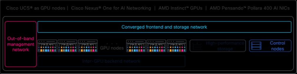
AI infrastructure using UCS—powered by AMD EPYC™ CPUs, AMD Instinct™ GPUs, and AMD Pensando™ Pollara 400 AI NICs—and Cisco Nexus One for AI Networking
The following sub-sections describe the components of this Cisco reference architecture for AI clusters.
This reference architecture uses Cisco UCS® C885A M8 Rack Server as the GPU nodes.
Cisco UCS® C885A M8 Rack Server
Cisco UCS® C885A M8 rack server (see Figure 2) is a dense GPU server purpose-built for large-scale AI training, fine-tuning, and inference workloads. It brings the Cisco and AMD architecture together in a single validated platform that combines 5th Gen AMD EPYC™ CPUs, AMD Instinct™ MI350X GPUs, and AMD Pensando™ Pollara 400 AI NICs for the east-west GPU interconnected fabric. Customers get a pre-validated AI node that shortens qualification cycles and accelerates time to production. Lifecycle and telemetry are unified through Cisco Intersight®, giving operators a consistent view from a single node to full multi-rack clusters.
|
|

Front view of the Cisco UCS® C885A M8 Rack Server with AMD Instinct™ GPUs and AMD Pensando™ Pollara 400 AI NICs
Figure 3 shows rear view of the Cisco UCS® C885A M8 rack server with interfaces and connectivity.
|
|
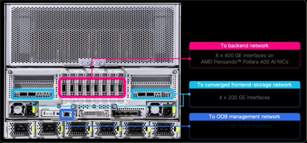
Rear view of the Cisco UCS® C885A M8 rack server showing interface connectivity
Cisco Intersight (see Figure 4) shifts AI infrastructure operations from reactive to proactive, addressing the significant challenges faced by operations teams and server administrators who struggle with increasing complexity, distributed environments, and the demands of AI workloads. Intersight works by leveraging a cloud-native, API-first architecture to deliver policy-based lifecycle management, automation, and unparalleled visibility, next-level training performance, and large-volume data processing.
|
|
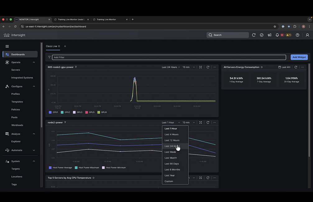
Cisco Intersight for life-cycle management of Cisco UCS
AMD Infinity Fabric™ (IF) is a high-speed intra-host interconnect that is used to connect multiple AMD CPUs and GPUs. For scale-up, AMD Infinity Fabric™ uses a global memory pool for inter-GPU communication. This gives massive bandwidth with smaller domains to run model parallelism traffic. For scale-out, the AMD Pensando™ Pollara 400 AI NICs support multiple modes that can be used to connect AMD Infinity Fabric™ nodes and clusters together over Ethernet to build large domains, which improves the performance of AI / ML training workloads.
AMD ROCm™ Collective Communication Library
The AMD ROCm™ Collective Communication Library (RCCL) uses a reliable multicast protocol called Group Multicast Library (GMLC) to ensure that all nodes in the collective communication group receive the same data. GMLC is a tree-based protocol that uses various techniques to help ensure reliability such as error detection, correction, and retransmission. In-network computation, performing AllReduce operations on the NIC, offloads the computation from the CPU, which improves performance and reduces latency. The AMD Pensando™ Software-in-Silicon Development Kit (SSDK) in conjunction with RCCL innovation, helps the NIC with atomic operations and performs the AllReduce operation in-place on the data buffer. The combination of these techniques allows AI deployments to achieve significant improvements for AllReduce operations in AI training.
AMD Instinct™ MI350 Series family of GPUs - COMMUNICATION, SCALING, and SYSTEMS
The AMD Instinct™ MI350 Series family of GPUs are designed to address two distinct sets of needs. For some customers, a drop-in compatible upgrade for the prior generation is ideal - offering fast deployment and preserving the existing infrastructure and ecosystem investments. But other customers are focused on pursuing the best performance and efficiency and are willing to adopt processors and systems with even greater power and cooling demands. To meet these twin demands, the AMD CDNA™ 4 architecture family maintains a similar communication and scaling approach as the prior generation to enable drop-in compatibility, while making incremental improvements to support the highest performance systems. The AMD CDNA™ 4 architecture comprises 8 AMD Infinity Fabric™ links that are 16-bits wide and fully bi-directional for inter-package communication within a single server node. In the prior generation, these were split across four IODs and operated at 32Gbps. The AMD Infinity Fabric™ links in the AMD CDNA™ 4 architecture run up to 20% faster generationally at 38.4Gbps for a total link bandwidth of 76.8GB/s in each direction and each of the repartitioned IODs contains four links. Each GPU offers >1TB/s of communication bandwidth within a node with one AMD Infinity Fabric™ link configured for PCIe® Gen 5 to connect to I/O devices such as storage and networking.
As Figure 5 illustrates, the system architecture for the AMD Instinct™ MI350 Series family is identical to the prior generation with a fully connected 8-GPU system. Each GPU uses one PCIe® Gen 5 link to connect to the host processors and I/O devices; this topology can flexibly handle all communication patterns within the server node. The AMD Instinct™ MI350 Series re-uses the OAM form factor with both 1000W and 1400W variants. The former is compatible with the previously deployed AMD Instinct™ MI325X generation designs, while the latter remains compatible but would require accommodations for higher power and cooling requirements.
|
|
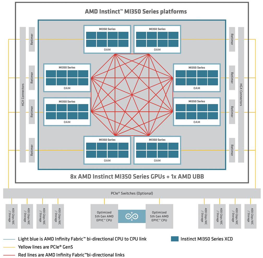
Figure 5.
AMD Instinct™ MI350 Series Platform 8-socket GPU design
Cisco Nexus One for AI Networking
Cisco Nexus One for AI networking combines custom silicon using Cisco Silicon One and Cloud Scale ASICs with high-performance N9000 series switches, advanced congestion-aware traffic management, integrated security, and centralized operations through on-premises Nexus Dashboard or cloud-managed Nexus Hyperfabric. Cisco further complements this architecture with validated reference designs developed in collaboration with key ecosystem partners.
Cisco N9364E-SG2 switches (see Figure 6), powered by Cisco Silicon One G200, provide 64 x 800 GE or 128 x 400 GE or 256 x 200 GE or 512 x 100 GE interfaces in 2 rack unit (RU) form factor. These switches are available in two models. Cisco N9364E-SG2-O offers ports in OSFP form factor, whereas Cisco N9364E-SG2-Q offers ports in QSFP-DD form factor. Except for the port form-factor, both switch models are similar. These switches can be used in the backend, frontend, and storage networks of an AI cluster.
|
|

Front-view of the Cisco N9364E-SG2-O switch powered by Cisco Silicon One G200
Cisco N9K-C93180YC-FX3 switch (see Figure 7) provides 48 x 1/10/25 GE and 6 x 40/100 GE interfaces in 1 RU form factor. This switch can be used in out-of-band management network for connecting the BMC and management ports on the GPU nodes and the management ports on the switches.
|
|

Front-view of the Cisco N9K-C93180YC-FX3 switch
Cisco Nexus Dashboard provides consistent and simplified on-premises management of all networks of an AI cluster, including the backend, frontend, storage, and the out-of-band management network. Key benefits include:
● Faster provisioning of RDMA fabrics: Built-in AI fabric types and templates with fine-tuned ECN thresholds and quality of service (QoS) of RoCEv2 traffic.
● Consistent operational experience: Support for all widely used fabric technologies, like VXLAN, routed fabrics (see Figure 8), and even the inter-fabric connectivity, thereby delivering a consistent operational experience for all networks of an AI cluster and even the peripheral networks.
● Congestion analytics: Real-time congestion scoring, statistics like ECN, drops, and microburst detection.
● AI job observability: Integration with Simple Linux Utility for Resource Management (SLURM) provides visibility into AI workloads.
● Anomaly detection: Proactive identification of performance bottlenecks with suggested remediation after an automatic correlation of distributed AI job and health of the network paths.
● Sustainability insights: Energy consumption monitoring and optimization recommendations.
|
|

Cisco Nexus Dashboard for on-premises management of networks
Cisco Nexus Hyperfabric (see Figure 9) provides simplified cloud management of all networks of an AI cluster. It eases lifecycle management of the network from initial design to deployment and ongoing monitoring. It also streamlines fabric experience by providing everything needed to manage multiple networks in one place.
|
|

Cisco Nexus Hyperfabric for cloud management of networks
This reference architecture offers flexibility to manage the networks of an AI cluster by Nexus Dashboard or Nexus Hyperfabric.
Cisco N9364E-SG2-O switches use OSFP-800G-DR8 twin-port transceivers (see Figure 10) with two 400G SMF MPO-12 connectors.
|
|

Cisco OSFP-800G-DR8 twin-port transceiver for Cisco N9364E-SG2-O switches
The AMD Pensando™ Pollara 400 AI NICs are compatible with Cisco QSFP-400G-DR4 transceiver (see Figure 11) with SMF MPO-12 connector.
|
|

Cisco QSFP-400G-DR4 transceiver for AMD Pensando™ Pollara 400 AI NICs
Figure 12 shows the connectivity between the AMD Pensando™ Pollara 400 AI NICs and the Cisco N9364E-SG2-O switches.
|
|
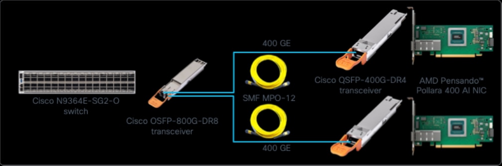
Connectivity between the AMD Pensando™ Pollara 400 AI NICs and the Cisco N9364E-SG2-O switches
The AMD Pensando™ Pollara 400 AI NICs are used for backend network connectivity in this reference architecture. The frontend connectivity of the GPU nodes is provided by two NICs, each with 2 x 200 GE interfaces, which AMD Pensando™ Pollara 400 AI NIC can support with security, and storage offloads. The frontend NICs also use the QSFP-400G-DR4 transceiver, but these interfaces operate at 200 GE. These 200 GE links are connected to the Cisco N9364E-SG2-O switches plugged with OSFP-800G-DR8 transceivers operating in 4 x 200 GE breakout mode.
This section provides topologies for the backend and the converged frontend and storage network of an AI cluster.
An Inter-GPU backend network connects the dedicated GPU NIC interfaces for running distributed jobs. This network is also known as the backend network, compute fabric, scale-out network, or east-west network.
Inter-GPU Backend Network Design Principles
The following are the design principles for the backend networks explained in this section:
Non-blocking Network Design
The inter-GPU backend networks should be non-blocking with no oversubscription. For example, on a 128-interface leaf switch, if 64 interfaces connect to the GPU NICs, the other 64 interfaces should connect to the spine switches. This non-oversubscribed design provides enough capacity when all the GPUs in a cluster send and receive traffic at full capacity simultaneously.
Rail-Optimized Network Design
Rail-optimized network design improves inter-GPU collective communication performance by allowing single-hop forwarding through the leaf switches without the traffic going to the spine switches.
A network is raiI-optimized within a scalable unit when the first GPU in all the nodes is connected to the same leaf switch, second GPU in all the nodes is connected to the same leaf switch, and so on. With eight GPUs in a node, rail-optimized connection scheme results in eight rails. The most common design is to dedicate one leaf switch per rail, resulting in eight leaf switches in a scalable unit (see Figure 13).
|
|
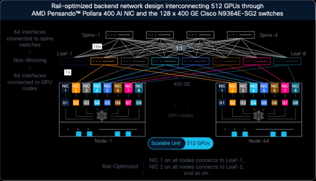
Figure 13.
A non-blocking rail-optimized network design based on 128-port 400 GE Cisco N9364E-SG2 switches for interconnecting 512 GPUs through AMD Pensando™ Pollara 400 AI NICs
Scalable units with fewer nodes can share leaf switches for multiple rails, for example one leaf switch for two rails resulting in four leaf switches in a scalable unit of 256 GPUs or one switch for four rails resulting in two leaf switches in a scalable unit of 128 GPUs. These designs are explained in the later sections.
Figure 13 shows a non-blocking and rail-optimized network design using 128-interface 400 GE Cisco N9364E-SG2 switches. This design has the following attributes:
● It connects 512 GPUs in 64 nodes, each with eight GPUs.
● Each GPU has a dedicated AMD Pensando™ Pollara 400 AI NIC.
● It is rail-optimized by connecting GPU 1 on all the GPU nodes to the first leaf switch, GPU 2 on all the GPU nodes to the second leaf switch, and so on.
● It has eight leaf switches and four spine switches connected using a non-blocking design.
To create a larger cluster, the design of Figure 13 can be expanded with multiple such networks interconnected between leaf and spine switches in a non-blocking way, as described in the later sections.
Tree-Based Network Design
In a tree-based network design, all GPUs in a node are connected to the same leaf switch (see Figure 14). In other words, tree-based design isn’t rail-optimized.
|
|

A non-blocking tree-based network design based on 128-port 400 GE Cisco N9364E-SG2 switches for interconnecting 512 GPUs with AMD Pensando™ Pollara 400 AI NICs
Comparison of Rail-Optimized and Tree-Based Network Designs
A rail-optimized design can have more GPUs benefitting from single-hop forwarding by leaf switches compared to the tree-based design. For example, using the rail-optimized network design in Figure 13, 512 GPUs can benefit from single-hop forwarding by leaf switches, whereas this benefit is limited to 64 GPUs in a tree-based design of Figure 14.
Another difference is that the rail-optimized network design requires relatively longer cable connections from all nodes to all leaf switches in a scalable unit, whereas tree-based design can use shorter, and therefore more affordable connections between the GPU NICs and the leaf switches.
Although rail-optimized designs are common, some deployments use tree-based network design because in those environments, most distributed jobs are expected to span across only to the GPUs connected to the same leaf switch, such as 64 GPUs in Figure 14.
Despite these differences, the component quantities, such as the number of switches, GPUs, NICs, and even the transceivers remain the same with both the designs.
Inter-GPU Backend Network for up to 128 GPUs
As explained earlier, smaller GPU clusters can share switches for multiple rails, eliminating the need for dedicated rail switches. As Figure 15 shows, both switches carry traffic for four rails each. The two switches are connected back-to-back to maintain non-blocking network design.
|
|

Inter-GPU backend network design connecting up to 128 GPUs through AMD Pensando™ Pollara 400 AI NICs and the 128-port 400 GE Cisco N9364E-SG2 switches
Inter-GPU Backend Network for 128 – 256 GPUs
As Figure 16 shows, a cluster of 128 – 256 GPUs can share one switch for two rails, resulting in four leaf switches for eight rails. The leaf switches are interconnected through spine switches to maintain a non-blocking design.
|
|
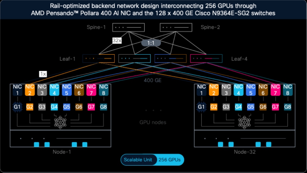
Inter-GPU backend network design connecting 128-256 GPUs through AMD Pensando™ Pollara 400 AI NICs and 128-port 400 GE Cisco N9364E-SG2 switches
Inter-GPU Backend Network for up to 256 – 512 GPUs
Figure 13 shows a cluster of 512 GPUs connected through AMD Pensando™ Pollara 400 AI NICs and the 128-port 400 GE Cisco N9364E-SG2 switches.
Larger GPU clusters in the Multiples of a Scalable Unit
A scalable unit is a set of GPU nodes and switches that can be repeatedly deployed for building larger AI clusters. The maximum number of GPUs in a scalable unit depends on the number of interfaces on the leaf switches, such as 512 GPUs in a scalable unit connected through 400G NICs and eight 128-port 400 GE switches shown in Figure 13. Smaller scalable units can also be deployed based on the factors like power and cooling availability, cabling distance, and job size requirements.
Typically, a scalable unit is connected in a rail-optimized design. As a result, traffic between the GPUs of a scalable unit benefits from the single hop forwarding by the leaf switches. However, traffic between the GPUs of different scalable units passes through spine switches.
For scenarios where partial scalable units are deployed initially and expansion is planned in the future, a strong recommendation is to deploy full set of switches required for the maximum size of the scalable unit. This approach avoids re-cabling, which is a time-consuming task due to a large number of cables in an AI cluster. Re-cabling also requires cluster downtime. For example, if only 128 GPUs (in 16 nodes) are deployed initially with a plan to expand the cluster to 512 GPUs, the inter-GPU backend network design should have eight leaf and four spine switches (see Figure 13) deployed initially. Smaller network, such as shown in Figure 15 and Figure 16 should be avoided. In other words, prefer the network design of Figure 15 and Figure 16 only when these clusters have absolutely no plans of expansion.
Inter-GPU Backend Network for 512 – 8,192 GPUs
To create a cluster of 512 – 8,192 GPUs, multiple scalable units can be interconnected between leaf and spine switches in a non-blocking way (see Figure 17).
|
|
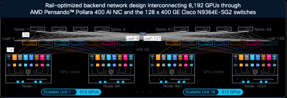
Inter-GPU backend network design connecting 512 – 8,192 GPUs through AMD Pensando™ Pollara 400 AI NICs and the 128-port 400 GE Cisco N9364E-SG2 switches
Maximum Scale of a Two-Tier Network
Using 400 Gbps links and 128 interfaces per switch, the maximum number of GPUs that can be connected to a two-tier network is 8,192. Here, leaf switches are counted for first tier, and the spine switches are counted for second tier. Connecting more GPUs to the same network at 400 Gbps speed requires a three-tier network with super-spine switches at the third layer, explained in the later sections.
An alternative approach would be to split the GPU NIC connectivity to multiple planes, known as a multi-plane design. For example, the 400 Gbps connectivity of the AMD Pensando™ Pollara 400 AI NICs can be split into 2 x 200 Gbps, with each link connected to a different switch in different network plane. This connectivity allows 256 x 200 Gbps interfaces on the switches. An increased number of switch interfaces (256 x 200 Gbps compared to 128 x 400 Gbps) allows more end-devices to be connected to a network without increasing network tiers, such as 32,768 GPUs to a dual-plane two-tier network using 200 Gbps links.
This reference architecture describes only single-plane designs. Reach out to your AMD or Cisco representatives with your requirements to build multi-plane AI clusters.
Connecting Fewer Scalable Units
Leaf switches are required only when more scalable units are added, but spine switches should be deployed for the planned scale to avoid re-cabling.
Consider Figure 17. It shows 16 scalable units, each with 512 GPUs and eight leaf switches. This results in a total of 128 leaf switches. Connecting these many leaf switches requires 64 spine switches, with one link between a leaf-spine pair. If, for example, 14 scalable units are required, even though 112 leaf switches are needed, but still 64 spines switches should be deployed with one link between each leaf-spine pair. Each spine would have 16 unused interfaces, which can be used for connecting two more scalable units in the future.
The key points to understand are:
● For 512 – 1,024 GPUs (1 – 2 scalable units), 8 spine switches are required.
● For 1,025 – 2,048 GPUs (3 – 4 scalable units), 16 spine switches are required.
● For 2,049 – 4,096 GPUs (5 – 8 scalable units), 32 spine switches are required.
● For 4097 – 8,192 GPUs (9 – 16 scalable units), 64 spine switches are required.
This approach ensures the same number of uplinks from a leaf switch to all spine switches, thereby avoiding congestion issues caused by a spine switch receiving more traffic than its collective downlink capacity.
Connecting Partial Scalable Units
As mentioned earlier, even for partial scalable units, leaf and spine switches required for the full scalable unit should be deployed. For example, for connecting 7,900 GPUs (15 scalable units with 512 GPUs and 16th scalable unit with 220 GPUs), 128 leaf switches and 64 spines switches should be deployed.
Inter-GPU Backend Network for 8K – 16K GPUs
As explained, using 400 Gbps links and 128-interface switch, connecting more than 8,192 GPUs requires a three-tier network with leaf, spine, and super-spine switches.
Figure 18 shows the network design for connecting 8K to 16K GPUs at 400 Gbps. Like the earlier designs, even this design has 512 GPUs and 8 leaf switches in a scalable unit. But the difference is that each scalable unit has 8 spine switches at the second tier of the network. Then, at the third layer, first spine switch of all scalable units is connected to the first set of super-spine switches. This set is known as core-1, plane-1, or super-spine plane 1. Likewise, second spine switch of all scalable units is connected to the second set of super-spine switches, called core-2, and so on.
|
|
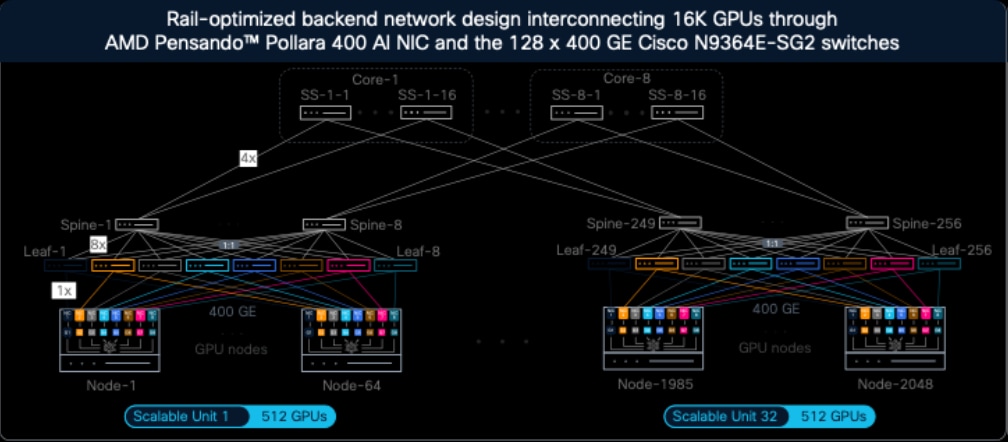
Inter-GPU backend network design connecting 8K – 16K GPUs through AMD Pensando™ Pollara 400 AI NIC and the 128-port 400 GE Cisco N9364E-SG2 switches
Inter-GPU Backend Network for 16K – 32K GPUs
Figure 19 shows the network design for connecting 16K to 32K GPUs at 400 Gbps based on the same design principles of the 16K GPU network design. As explained earlier, for connecting 33-64 scalable units (16K – 32K GPUs), 32 super-spine switches in eight cores must be deployed. The same principles can be used for a 64K GPU cluster design.
|
|

Inter-GPU backend network design connecting 16K – 32K GPUs through AMD Pensando™ Pollara 400 AI NIC and the 128-port 400 GE Cisco N9364E-SG2 switches
Component Count for Backend Network
Table 1 shows the number of switches, transceivers, and cable required to interconnect 32 – 32K GPUs through AMD Pensando™ Pollara 400 AI NIC and the 128-port 400 GE Cisco N9364E-SG2 switches.
Table 1. Component count for inter-GPU backend network
| Compute count |
Switch count |
Transceiver count |
Cables |
|||||||
| GPUs |
Nodes |
SUs |
Leaf switches |
Spine switches |
Super-spine switches |
Total switches |
In nodes |
In switches |
Node to leaf |
Switch to switch |
| 32 |
4 |
1 |
2 |
- |
- |
2 |
32 |
128 |
32 |
32 |
| 64 |
8 |
1 |
2 |
- |
- |
2 |
64 |
128 |
64 |
64 |
| 128 |
16 |
1 |
2 |
- |
- |
2 |
128 |
128 |
128 |
128 |
| 256 |
32 |
1 |
4 |
2 |
- |
6 |
256 |
384 |
256 |
256 |
| 512 |
64 |
1 |
8 |
4 |
- |
12 |
512 |
768 |
512 |
512 |
| 1,024 |
128 |
2 |
16 |
8 |
- |
24 |
1,024 |
1,536 |
1,024 |
1,024 |
| 2,048 |
256 |
4 |
32 |
16 |
- |
48 |
2,048 |
3,072 |
2,048 |
2,048 |
| 4,096 |
512 |
8 |
64 |
32 |
- |
96 |
4,096 |
6,144 |
4,096 |
4,096 |
| 8,192 |
1,024 |
16 |
128 |
64 |
- |
192 |
8,192 |
12,288 |
8,192 |
8,192 |
| 16,384 |
2,048 |
32 |
256 |
256 |
128 |
640 |
16,384 |
40,960 |
16,384 |
32,768 |
| 32,768 |
4,096 |
64 |
512 |
512 |
256 |
1,280 |
32,768 |
81,920 |
32,768 |
65,536 |
Converged Frontend and Storage Network
The converged frontend and storage network carries traffic between GPU nodes, storage nodes, control nodes (where cluster management applications are hosted), and the users or agents outside the cluster.
The following are the design principles used in this section:
Most network capacity is used for the storage traffic. The designs in this section are based on storage traffic throughput of at least 1 GBps per GPU. The network is oversubscribed for this capacity at the leaf switches connected to the GPU nodes. These switches are addressed as the compute-leaf switches in this document. Oversubscription doesn’t exist at the spine switches and at the leaf switches connected to the storage nodes (addressed as the storage-leaf switches in this document).
Storage vendors may have different guidelines, which should be accounted for the final design.
The designs in this section are based on two NICs, each offering 2 x 200 GE, per GPU node. This means, GPU node connects to the converged frontend and storage network using 4 x 200 GE interfaces. The designs can be modified for other configurations.
The designs in this section assume storage nodes connected at 200 Gbps.
The designs in this section account for the spare interfaces at 200 Gbps on the switches for connecting the control nodes. These interfaces can also operate at 100 Gbps.
The designs in this section use the same Cisco N9364E-SG2 switch for providing consistent operations across frontend and backend networks of an AI cluster. This switch offers 256 x 200 GE interfaces. The design can be modified for the Cisco N9K-C9364D-GX2A switch offering 128 x 200 GE interfaces or even the N9K-C9332D-GX2B offering 64 x 200 GE interfaces, especially for the storage-leaf or control-leaf switches.
All GPU nodes are connected to two switches. Also, the two interfaces on a NIC are connected to two different switches.
Converged Frontend and Storage Network for up to 512 GPUs
Figure 20 shows the network design for converged frontend and storage network for connecting up to 64 GPU nodes, each with 4 x 200 GE interfaces, interconnected through Cisco N9364E-SG2 switches. Following are the attributes of this design:
● Each switch connects to 2 x 200 GE interfaces on the 64 GPU nodes, consuming 128 x 200 GE interfaces per switch.
● Each switch accounts for 12 x 200 GE interfaces for storage connectivity resulting in a combined storage throughput of 2 x 12 x 200 = 4,800 Gbps. This is enough to provide 1 GBps or 8 Gbps of storage throughput to 512 GPUs in a scalable unit.
● Each switch accounts for 12 x 200 GE or 24 x 100 GE interfaces for connecting the control nodes.
● The spare interfaces on the switches can be connected to the border devices.
|
|
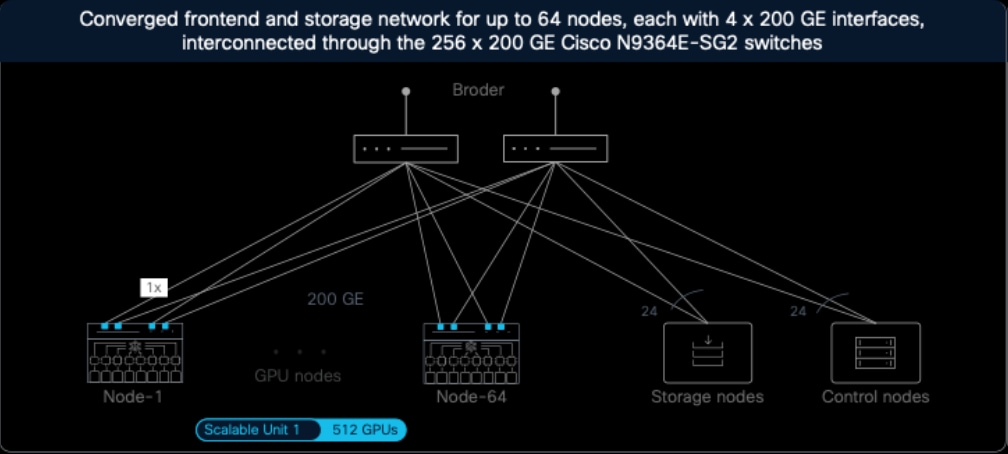
Converged frontend and storage network design for connecting up to 64 GPU nodes
Converged Frontend and Storage Network for 512 – 4K GPUs
Figure 21 shows the network design for converged frontend and storage network for connecting multiple scalable units, each with 64 GPU nodes, interconnected through Cisco N9364E-SG2 switches.
Following are the attributes of this design:
● Each scalable unit has dedicated two compute-leaf switches, each connecting 2 x 200 GE interfaces to the 64 GPU nodes, consuming 128 x 200 GE interfaces per switch as downlinks.
● Each compute-leaf has 12 x 200 GE uplinks to the two spine switches, with 6 x 200 GE links between a leaf-spine pair. For two compute-leaf switches, this provides 2 x 12 x 200 Gbps = 4,800 Gbps, which is enough to provide 1 GB/s or 8 Gbps of throughput per 512 GPUs in a scalable unit.
● Two (or a pair of) storage-leaf switches offer 84 x 200 GE (scalable up to 128) downlinks to the storage nodes. This provides 2 x 84 x 200 = 33,600 Gbps for 4,096 GPUs or ~1 GBps per GPU.
● Relatively smaller environments can connect the control nodes to the spare interfaces on the storage-leaf switches, thereby eliminating the dedicated control-leaf switches.
● Eight pairs of compute-leaf switches (192 uplinks) and a pair of storage-leaf switches (168 uplinks) can be interconnected through two spines. After connecting 48 x 200 GE links to control-leaf switches, spare interfaces can be connected to border devices.
|
|

Converged frontend and storage network design for connecting 512 – 4K GPU nodes
Converged Frontend and Storage Network for up to 4K-32K GPUs
Figure 22 shows the network design for converged frontend and storage network for connecting multiple scalable units, each with 64 GPU nodes, interconnected through Cisco N9364E-SG2 switches. It extends the same design principles of Figure 21.
Following are the attributes of this design:
● Each scalable unit has dedicated two compute-leaf switches, with each connecting 2 x 200 GE interfaces on the 64 GPU nodes, consuming 128 x 200 GE interfaces per switch as downlinks.
● Each compute-leaf has 12 x 200 GE uplinks to the 12 spine switches, with 1 x 200 GE links per leaf-spine pair. For two compute-leaf switches, this provides 2 x 12 x 200 Gbps = 4,800 Gbps, which is enough to provide 1 GB/s or 8 Gbps of throughput per 512 GPUs in a scalable unit.
● Twelve (or six pairs of) storage-leaf switches offer 120 x 200 GE downlinks per switch to the storage nodes. This provides 12 x 120 x 200 = 288,000 Gbps for 32,768 GPUs or ~1 GBps per GPU.
● 64 pairs of compute-leaf switches (1,536 uplinks) and six pairs of storage-leaf switches (1,440 uplinks) can be interconnected through 12 spines. After connecting 48 x 200 GE links to control-leaf switches, spare interfaces can be connected to border devices.
|
|

Converged frontend and storage network design for connecting 4K-32K GPU nodes
Component Count for Frontend Network
Table 2 shows the number of switches and transceivers required for the converged frontend and storage network for connecting 64 – 4,096 GPU nodes through the Cisco N9364E-SG2 switches.
Table 2. Component count for converged frontend and storage network
| Compute count |
Switch count |
Transceiver count |
|||||||
| GPUs |
Nodes |
SUs |
Compute-leaf switches |
Storage-leaf switches |
Control-leaf switches |
Spine switches |
Total switches |
In nodes |
In switches |
| 512 |
64 |
1 |
2 |
- |
|
- |
2 |
256 |
261 |
| 1,024 |
128 |
2 |
4 |
2 |
- |
2 |
8 |
512 |
530 |
| 2,048 |
256 |
4 |
8 |
2 |
- |
2 |
12 |
1,024 |
1,052 |
| 4,096 |
512 |
8 |
16 |
2 |
2 |
2 |
22 |
2,048 |
2,100 |
| 8,192 |
1,024 |
16 |
32 |
4 |
2 |
4 |
42 |
4,096 |
4,196 |
| 16,384 |
2,048 |
32 |
64 |
6 |
2 |
6 |
78 |
8,192 |
8,380 |
| 32,768 |
4,096 |
64 |
128 |
12 |
2 |
12 |
154 |
16,384 |
16,756 |
Out-of-band Management Network
A scalable unit requires the following types and quantities of out-of-band management connectivity:
● 1 x 1 GE and 2 x 10 GE per compute node, resulting in 64 x 1 GE and 128 x 10 GE per scalable unit.
● 1 x 1 GE per N9364E-SG2 switch, resulting in 8 x 1 GE for backend leaf switches and 2 x 1 GE for frontend leaf switches.
● Additional connections for power distribution units, etc.
Each scalable unit is assigned five N9K-C93108TC-FX3, allowing 48 x 5 = 240 x 1/10 GE downlinks, which are enough for the connections. These switches can be interconnected through N9364E-SG2 as spines. For smaller scale, N9K-C9364D-GX2A or N9K-C9332D-GX2B can also be used.
Security in an AI infrastructure is crucial to ensure confidentiality, integrity, and high availability against adversarial attacks by implementing robust access controls and host and network isolation to prevent unauthorized access or manipulation. Several Cisco security technologies, as enumerated below, are available that can be deployed to configure, monitor, and enforce end-to-end security right from applications to overall infrastructure.
Observability is a key element of AI infrastructure to ensure continuous visibility and reliability and to provide high-performance by tuning as well as proper infrastructure scaling. It also facilitates debugging, aids security, helps maintain trustworthy and effective AI systems. Cisco Splunk® is an industry-leading observability solution to ingest significant amounts of telemetry and gain in-depth insights.
The overall solution has been thoroughly tested considering all aspects of management plane, control plane, and data plane combining compute, storage, and networking together. Several benchmark test suites such as HPC Benchmark, single and multi-hop IB PerfTest, collective communications tests, and high-availability (across switch and link failure) tests, MLCommons Training and Inference benchmarks have also been run to evaluate end-to-end performance and assist with tuning. Explore more on benchmarking results.
The principles and designs explained in this reference architecture can be used to build high-performing, secure, and scalable AI clusters.
Refer to the following documents for more information:
● AMD AI Networking Direction and Strategy: https://www.amd.com/content/dam/amd/en/documents/pensando-technical-docs/article/amd-ai-networking-direction-and-strategy.pdf
● AMD CDNA™ 4 ARCHITECTURE: https://www.amd.com/content/dam/amd/en/documents/instinct-tech-docs/white-papers/amd-cdna-4-architecture-whitepaper.pdf
● AMD Pensando™ Pollara 400 AI NIC Product Brief: https://www.amd.com/content/dam/amd/en/documents/pensando-technical-docs/product-briefs/pollara-product-brief.pdf
● Cisco Nexus Hyperfabric: https://www.cisco.com/site/us/en/products/networking/data-center-networking/nexus-hyperfabric/index.html
● Cisco Nexus Dashboard: https://www.cisco.com/site/us/en/products/networking/cloud-networking/nexus-platform/index.html
● Cisco N9364E-SG2 Switches Data Sheet: https://www.cisco.com/c/en/us/products/collateral/switches/nexus-9000-series-switches/nexus-9364e-sg2-switch-ds.html
● Cisco N9300-FX3 Series Switches Data Sheet: https://www.cisco.com/c/en/us/products/collateral/switches/nexus-9000-series-switches/datasheet-c78-744052.html
● Benchmarking scale-out AI fabrics with Cisco N9000 + AMD Pensando™ Pollara 400 NICs: https://blogs.cisco.com/datacenter/benchmarking-scale-out-ai-fabrics-with-cisco-n9000-amd-pensando-pollara-400-nics
● High-Performance AI Infrastructure Cisco and AMD Solution Overview: https://www.cisco.com/c/en/us/products/collateral/switches/nexus-9000-series-switches/high-performance-ai-infra-amd-so.html