Information About Access and Trunk Interfaces
 Note |
See the Cisco Nexus 9000 Series NX-OS High Availability and Redundancy Guide for complete information on high-availability features. |
Note |
The device supports only IEEE 802.1Q-type VLAN trunk encapsulation. |
About Access and Trunk Interfaces
A Layer 2 port can be configured as an access or a trunk port as follows:
-
An access port can have only one VLAN configured on that port; it can carry traffic for only one VLAN.
-
A trunk port can have two or more VLANs configured on that port; it can carry traffic for several VLANs simultaneously.
By default, all the ports on Cisco Nexus 9300-EX switches are Layer 3 ports and all the ports on Cisco Nexus 9300 switches are Layer 2 ports.
You can make all ports Layer 2 ports using the setup script or by entering the system default switchport command. See the Cisco Nexus 9000 Series NX-OS Fundamentals Configuration Guide for information about using the setup script. To configure the port as a Layer 2 port using the CLI, use the switchport command.
All ports in the same trunk must be in the same VDC, and trunk ports cannot carry VLANs from different VDCs.
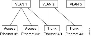
The following figure shows how you can use trunk ports in the network. The trunk port carries traffic for two or more VLANs.
Note |
See the Cisco Nexus 9000 Series NX-OS Layer 2 Switching Configuration Guide for information about VLANs. |
In order to correctly deliver the traffic on a trunk port with several VLANs, the device uses the IEEE 802.1Q encapsulation, or tagging, method (see the “IEEE 802.1Q Encapsulation” section for more information).
Note |
See the Cisco Nexus 9000 Series NX-OS Unicast Routing Configuration Guide for information about subinterfaces on Layer 3 interfaces. |
To optimize the performance on access ports, you can configure the port as a host port. Once the port is configured as a host port, it is automatically set as an access port, and channel grouping is disabled. Use the host designation to decrease the time that it takes the designated port to begin to forward packets.
Only an end station can be set as a host port; you will receive an error message if you attempt to configure other ports as hosts.
If an access port receives a packet with an 802.1Q tag in the header other than the access VLAN value, that port drops the packet without learning its MAC source address.
A Layer 2 interface can function as either an access port or a trunk port; it cannot function as both port types simultaneously.
When you change a Layer 2 interface back to a Layer 3 interface, that interface loses all the Layer 2 configuration and resumes the default VLAN configurations.
IEEE 802.1Q Encapsulation
Note |
For information about VLANs, see the Cisco Nexus 9000 Series NX-OS Layer 2 Switching Configuration Guide. |
A trunk is a point-to-point link between the switch and another networking device. Trunks carry the traffic of multiple VLANs over a single link and allow you to extend VLANs across an entire network.
To correctly deliver the traffic on a trunk port with several VLANs, the device uses the IEEE 802.1Q encapsulation, or tagging, method that uses a tag that is inserted into the frame header. This tag carries information about the specific VLAN to which the frame and packet belong. This method allows packets that are encapsulated for several different VLANs to traverse the same port and maintain traffic separation between the VLANs. Also, the encapsulated VLAN tag allows the trunk to move traffic end-to-end through the network on the same VLAN.
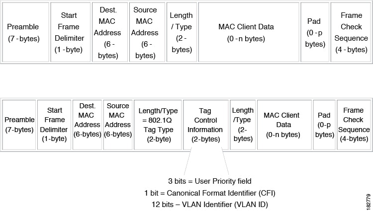
Drop Eligible Indicator
When Nexus 9000 switch receives a frame with DEI bit set to 1, it is forwarded as is to the next hop. For example, if the next hop is Nexus 6000, it drops frames on receiving a packet with the DEI bit set to 1 in the dot1q header.
Beginning with Cisco Nexus NX-OS release 10.2(3)F, the DEI bit is cleared whenever a frame is received with DEI bit set to 1.
switch# conf t
Enter configuration commands, one per line. End with CNTL/Z.
switch(config)# system default reset-dei
switch(config)switch# conf t
Enter configuration commands, one per line. End with CNTL/Z.
switch(config)# no system default reset-dei
switch(config)Access VLANs
When you configure a port in access mode, you can specify which VLAN will carry the traffic for that interface. If you do not configure the VLAN for a port in access mode, or an access port, the interface carries traffic for the default VLAN (VLAN1).
You can change the access port membership in a VLAN by specifying the new VLAN. You must create the VLAN before you can assign it as an access VLAN for an access port. If you change the access VLAN on an access port to a VLAN that is not yet created, the system shuts that access port down.
If an access port receives a packet with an 802.1Q tag in the header other than the access VLAN value, that port drops the packet without learning its MAC source address.
Native VLAN IDs for Trunk Ports
A trunk port can carry nontagged packets simultaneously with the 802.1Q tagged packets. When you assign a default port VLAN ID to the trunk port, all untagged traffic travels on the default port VLAN ID for the trunk port, and all untagged traffic is assumed to belong to this VLAN. This VLAN is referred to as the native VLAN ID for a trunk port. That is, the native VLAN ID is the VLAN that carries untagged traffic on trunk ports.
Note |
Native VLAN ID numbers must match on both ends of the trunk. |
The trunk port sends an egressing packet with a VLAN that is equal to the default port VLAN ID as untagged; all the other egressing packets are tagged by the trunk port. If you do not configure a native VLAN ID, the trunk port uses the default VLAN.
Note |
You cannot use a Fibre Channel over Ethernet (FCoE) VLAN as a native VLAN for an Ethernet trunk switchport. |
Tagging Native VLAN Traffic
The Cisco software supports the IEEE 802.1Q standard on trunk ports. In order to pass untagged traffic through the trunk ports, you must create a VLAN that does not tag any packets (or you can use the default VLAN). Untagged packets can pass through trunk ports and access ports.
However, all packets that enter the device with an 802.1Q tag that matches the value of the native VLAN on the trunk are stripped of any tagging and egress the trunk port as untagged packets. This situation can cause problems because you may want to retain the tagging on packets on the native VLAN for the trunk port.
You can configure the device to drop all untagged packets on the trunk ports and to retain the tagging of packets entering the device with 802.1Q values that are equal to that of the native VLAN ID. All control traffic still passes on the native VLAN. This configuration is global; trunk ports on the device either do or do not retain the tagging for the native VLAN.
Allowed VLANs
By default, a trunk port sends traffic to and receives traffic from all VLANs. All VLAN IDs are allowed on each trunk. However, you can remove VLANs from this inclusive list to prevent traffic from the specified VLANs from passing over the trunk. Later, you can add any specific VLANs that you may want the trunk to carry traffic for back to the list.
To partition the Spanning Tree Protocol (STP) topology for the default VLAN, you can remove VLAN1 from the list of allowed VLANs. Otherwise, VLAN1, which is enabled on all ports by default, will have a very big STP topology, which can result in problems during STP convergence. When you remove VLAN1, all data traffic for VLAN1 on this port is blocked, but the control traffic continues to move on the port.
Note |
See the Cisco Nexus 9000 Series NX-OS Layer 2 Switching Configuration Guide for more information about STP. |
Note |
You can change the block of VLANs reserved for internal use. See the Cisco Nexus 9000 Series NX-OS Layer 2 Switching Configuration Guide for more information about changing the reserved VLANs. |
Default Interfaces
You can use the default interface feature to clear the configured parameters for both physical and logical interfaces such as the Ethernet, loopback, VLAN network, tunnel, and the port-channel interface.
Note |
A maximum of eight ports can be selected for the default interface. The default interfaces feature is not supported for management interfaces because the device could go to an unreachable state. |
Switch Virtual Interface and Autostate Behavior
In Cisco NX-OS, a switch virtual interface (SVI) represents a logical interface between the bridging function and the routing function of a VLAN in the device.
The operational state of this interface is governed by the state of the various ports in its corresponding VLAN. An SVI interface on a VLAN comes up when at least one port in that VLAN is in the Spanning Tree Protocol (STP) forwarding state. Similarly, this interface goes down when the last STP forwarding port goes down or goes to another STP state.
High Availability
See the Cisco Nexus 9000 Series NX-OS High Availability and Redundancy Guide for complete information about high availability features.
Counter Values
See the following information on the configuration, packet size, incremented counter values, and traffic.
|
Configuration |
Packet Size |
Incremented Counters |
Traffic |
|---|---|---|---|
|
L2 port – without any MTU configuration |
6400 and 10000 |
Jumbo, giant, and input error |
Dropped |
|
L2 port – with jumbo MTU 9216 in network-qos configuration |
6400 |
Jumbo |
Forwarded |
|
L2 port – with jumbo MTU 9216 in network-qos configuration |
10000 |
Jumbo, giant, and input error |
Dropped |
|
Layer 3 port with default Layer 3 MTU and jumbo MTU 9216 in network-qos configuration |
6400 |
Jumbo |
Packets are punted to the CPU (subjected to CoPP configs), get fragmented, and then they are forwarded by the software. |
|
Layer 3 port with default Layer 3 MTU and jumbo MTU 9216 in network-qos configuration |
6400 |
Jumbo |
Packets are punted to the CPU (subjected to CoPP configs), get fragmented, and then they are forwarded by the software. |
|
Layer 3 port with default Layer 3 MTU and jumbo MTU 9216 in network-qos configuration |
10000 |
Jumbo, giant, and input error |
Dropped |
|
Layer 3 port with jumbo Layer 3 MTU and jumbo MTU 9216 in network-qos configuration |
6400 |
Jumbo |
Forwarded without any fragmentation. |
|
Layer 3 port with jumbo Layer 3 MTU and jumbo MTU 9216 in network-qos configuration |
10000 |
Jumbo, giant, and input error |
Dropped |
|
Layer 3 port with jumbo Layer 3 MTU and default L2 MTU configuration |
6400 and 10000 |
Jumbo, giant, and input error |
Dropped |
Note |
|
 Feedback