Licensing Requirements
See the Cisco NX-OS Licensing Guide and Cisco NX-OS Licensing Options Guide for Cisco NX-OS licensing recommendations and instructions to obtain and apply licenses.
The documentation set for this product strives to use bias-free language. For the purposes of this documentation set, bias-free is defined as language that does not imply discrimination based on age, disability, gender, racial identity, ethnic identity, sexual orientation, socioeconomic status, and intersectionality. Exceptions may be present in the documentation due to language that is hardcoded in the user interfaces of the product software, language used based on RFP documentation, or language that is used by a referenced third-party product. Learn more about how Cisco is using Inclusive Language.
This chapter contains these sections.
See the Cisco NX-OS Licensing Guide and Cisco NX-OS Licensing Options Guide for Cisco NX-OS licensing recommendations and instructions to obtain and apply licenses.
See the Nexus Switch Platform Support Matrix to know from which Cisco NX-OS releases various Cisco Nexus 9000 and 3000 switches support a selected feature.
Layer 3 unicast routing involves two activities
determining optimal routing paths, and
packet switching.
You can use routing algorithms to calculate the optimal path from the router to a destination. This calculation depends on the algorithm selected, route metrics, and other considerations such as load balancing and alternate path discovery.
Routing protocols use a metric to evaluate the best path to the destination. A metric is a standard of measurement, such as a path bandwidth, that routing algorithms use to determine the optimal path to a destination.
To aid path determination, routing algorithms initialize and maintain routing tables. Routing tables contain route information such as the IP destination address, the address of the next router, or the next hop. Routers use destination and next-hop associations to determine which router represents the next hop on the way to the destination. When a router receives an incoming packet, it checks the destination address and attempts to associate this address with the next hop. See the Unicast RIB section for more information about the route table.
Routing tables can contain other information, such as the data about the desirability of a path. Routers compare metrics to determine optimal routes. These metrics differ depending on the design of the routing algorithm used. See the Routing Metrics section.
Routers communicate with one another and transmit a variety of messages to maintain their routing tables. The routing update message is one such message that consists of all or a portion of a routing table. Routers analyze routing updates from all the other routers to build a detailed picture of the network topology. A link-state advertisement is another example of such a message that informs other routers of the link state of the sending router. Routers also use link information to determine optimal routes to network destinations. For more information, see the Routing Algorithms section.
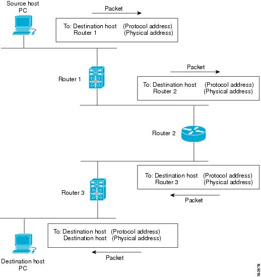
In packet switching, a host determines that it must send a packet to another host. After acquiring a router address by some means, the source host sends a packet that is addressed specifically to the physical (Media Access Control [MAC]-layer) address of the router, but with the IP (network layer) address of the destination host.
The router checks destination IP in the routing table. If the router does not find the destination IP address in the routing table, it drops the packet. If the router finds the destination address in the routing table, the router changes the destination MAC address to the MAC address of the next-hop router and transmits the packet.
The next hop might be the ultimate destination host or another router that executes the same switching decision process. As the packet moves through the internetwork, its physical address changes, but its protocol address remains constant. See the figure Packet Header Updates Through a Network for reference.
Routing algorithms use a variety of metrics to determine the best route. Sophisticated routing algorithms can base route selection on multiple metrics.
The path length is the most common routing metric. Some routing protocols allow you to assign arbitrary costs to each network link. The path length, in these protocols, is the sum of the costs for each traversed link.
Other routing protocols define the hop count. The hop count refers to the number of passes through internetworking products, such as routers, that a packet must take from a source to a destination.
The reliability, in the context of routing algorithms, is the dependability (in terms of the bit-error rate) of each network link. Some network links might go down more often than others. After a network fails, certain network links might be repaired more easily or more quickly than other links.
The reliability factors that you can take into account when assigning the reliability rating are arbitrary numeric values that you usually assign to network links.
Routing delay is the length of time required to move a packet from a source to a destination through the internetwork. Routing delay depends on many factors such as
bandwidth of intermediate network links
port queues at each router along the way
network congestion on all intermediate network links, and
physical distance that the packet must travel.
Because the routing delay is a combination of several important variables, it is a common and useful metric.
The bandwidth is the available traffic capacity of a link. For example, a 10-Gigabit Ethernet link is preferable to a 1-Gigabit Ethernet link. Although the bandwidth is the maximum attainable throughput on a link, links with greater bandwidth do not always provide better routes than slower links. For example, a busy faster link might require more time to send a packet to its destination than a slower link.
The load is the degree to which a network resource, such as a router, is busy. You can calculate the load in a variety of ways, including CPU usage and packets processed per second. Monitoring these parameters on a continual basis can be resource intensive.
The communication cost is a measure of the operating cost to route over a link. The communication cost is another important metric, especially if you do not care about performance as much as operating expenditures. For example, the line delay for a private line might be longer than a public line. However, you can choose to send packets over your private line rather than through the public lines that cost money for usage time.
Each routing process has an associated router ID. You can configure the router ID to any interface in the system. If you do not configure the router ID, Cisco NX-OS selects the router ID based on the following criteria:
Cisco NX-OS prefers loopback0 over any other interface. If loopback0 does not exist, then Cisco NX-OS prefers the first loopback interface over any other interface type.
If you have not configured a loopback interface, Cisco NX-OS uses the first interface in the configuration file as the router ID. If you configure any loopback interface after Cisco NX-OS selects the router ID, the loopback interface becomes the router ID. If the loopback interface is not loopback0 and you configure loopback0 with an IP address, the router ID changes to the IP address of loopback0.
If the interface that the router ID is based on changes, that new IP address becomes the router ID. If any other interface changes its IP address, there is no router ID change.
An autonomous system (AS) is a network controlled by a single technical administration entity. Autonomous systems divide global external networks into individual routing domains, where local routing policies are applied. This organization simplifies routing domain administration and simplifies consistent policy configuration.
Each autonomous system can support multiple interior routing protocols that dynamically exchange routing information through route redistribution. The Regional Internet Registries (RIR) assign a unique number to each public autonomous system that directly connects to the Internet. This autonomous system number (AS number) identifies both the routing process and the autonomous system.
The Border Gateway Protocol (BGP) supports 4-byte AS numbers that can be represented in asplain and asdot notations:
asplain—A decimal value notation where both 2-byte and 4-byte AS numbers are represented by their decimal value. For example, 65526 is a 2-byte AS number, and 234567 is a 4-byte AS number.
asdot—An AS dot notation where 2-byte AS numbers are represented by their decimal value and 4-byte AS numbers are represented by a dot notation. For example, 2-byte AS number 65526 is represented as 65526, and 4-byte AS number 65546 is represented as 1.10.
The BGP 4-byte AS number capability is used to propagate 4-byte-based AS path information across BGP speakers that do not support 4-byte AS numbers.
 Note |
RFC 5396 is partially supported. The asplain and asdot notations are supported, but the asdot+ notation is not. |
Private autonomous system numbers are used for internal routing domains but must be translated by the router for traffic that is routed out to the Internet. You should not configure routing protocols to advertise private autonomous system numbers to external networks. By default, Cisco NX-OS does not remove private autonomous system numbers from routing updates.
Note |
The autonomous system number assignment for public and private networks is governed by the Internet Assigned Number Authority (IANA). For information about autonomous system numbers, including the reserved number assignment, or to apply to register an autonomous system number, see this URL:http://www.iana.org/ |
A key aspect to measure for any routing algorithm is how much time a router takes to react to network topology changes. When a part of the network changes for any reason, such as a link failure, the routing information in different routers might not match. Some routers will have updated information about the changed topology, while other routers will still have the old information. The convergence is the amount of time before all routers in the network have updated, matching routing information. The convergence time varies depending on the routing algorithm. Fast convergence minimizes the chance of lost packets caused by inaccurate routing information.
Routing protocols can use load balancing or equal cost multipath (ECMP) to share traffic across multiple paths. When a router learns multiple routes to a specific network, it installs the route with the lowest administrative distance in the routing table. If the router receives and installs multiple paths with the same administrative distance and cost to a destination, load balancing can occur. Load balancing distributes the traffic across all the paths, sharing the load. The number of paths used is limited by the number of entries that the routing protocol puts in the routing table. For the number of ECMP paths supported by each routing protocol, see the Cisco Nexus 9000 Series NX-OS Verified Scalability Guide.
Note |
ECMP does not guarantee equal load-balancing across all links. It guarantees only that a particular flow will choose one particular next hop at any point in time. |
If you have multiple routing protocols configured in your network, you can configure these protocols to share routing information by configuring route redistribution in each protocol. For example, you can configure the Open Shortest Path First (OSPF) protocol to advertise routes learned from the Border Gateway Protocol (BGP). You can also redistribute static routes into any dynamic routing protocol. The router that is redistributing routes from another protocol sets a fixed route metric for those redistributed routes, which prevents incompatible route metrics between the different routing protocols. For example, routes redistributed from EIGRP into OSPF are assigned a fixed link cost metric that OSPF understands.
Note |
You are required to use route maps when you configure the redistribution of routing information. |
Route redistribution also uses an administrative distance (see the Administrative Distance section) to distinguish between routes learned from two different routing protocols. The preferred routing protocol is given a lower administrative distance so that its routes are picked over routes from another protocol with a higher administrative distance assigned.
An administrative distance is a rating of the trustworthiness of a routing information source. A higher value indicates a lower trustworthiness. Typically, a route can be learned through more than one protocol. Administrative distance is used to discriminate between routes learned from more than one protocol. The route with the lowest administrative distance is installed in the IP routing table.
You can use stub routing in a hub-and-spoke network topology. In stub routing, one or more end (stub) networks are connected to a remote router (the spoke) that is again connected to one or more distribution routers (the hub). The remote router is adjacent only to one or more distribution routers.
IP traffic can reach the remote router only through a distribution router. This type of configuration is commonly used in WAN topologies in which the distribution router is directly connected to a WAN. The distribution router can be connected to many more remote routers. Often, the distribution router is connected to 100 or more remote routers. In a hub-and-spoke topology, the remote router must forward all nonlocal traffic to a distribution router, so it becomes unnecessary for the remote router to hold a complete routing table. Generally, the distribution router sends only a default route to the remote router.
Only specified routes are propagated from the remote (stub) router. The stub router responds to all queries for summaries, connected routes, redistributed static routes, external routes, and internal routes with the message “inaccessible.” A router that is configured as a stub sends a special peer information packet to all neighboring routers to report its status as a stub router.
Any neighbor that receives a packet that informs it of the stub status does not query the stub router for any routes, and a router that has a stub peer does not query that peer. The stub router depends on the distribution router to send the proper updates to all peers.
The following figure shows a simple hub-and-spoke configuration.
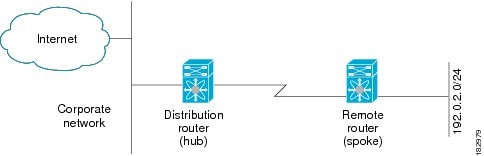
Stub routing does not prevent routes from being advertised to the remote router. The figure Simple Hub-and-Spoke Network shows that the remote router can access the corporate network and the Internet through the distribution router only. A full route table on the remote router, in this example, serves no functional purpose because the path to the corporate network and the Internet is always through the distribution router. A larger route table reduces only the amount of memory required by the remote router. The bandwidth and memory used can be lessened by summarizing and filtering routes in the distribution router. In this network topology, the remote router does not need to receive routes that have been learned from other networks because the remote router must send all nonlocal traffic, regardless of its destination, to the distribution router. To configure a true stub network, you should configure the distribution router to send only a default route to the remote router.
OSPF supports stub areas, and the Enhanced Interior Gateway Routing Protocol (EIGRP) supports stub routers.
Note |
Use the EIGRP stub routing feature only on stub devices. A stub device connects to the network core or distribution layer, and core transit traffic should not flow through it. IP traffic can reach the remote router only through a distribution router. A stub device should not have any EIGRP neighbors other than distribution devices. Ignoring this restriction will cause undesirable behavior. |
Routing algorithms determine how a router
gathers and reports reachability information
deals with topology changes
determines the optimal route to a destination
Various types of routing algorithms exist. Each algorithm has a different impact on network and router resources. Routing algorithms use a variety of metrics that affect calculation of optimal routes. You can classify routing algorithms by type, such as static or dynamic, and interior or exterior.
Static routes are route table entries that you manually configure. These static routes do not change unless you reconfigure them. Static routes are simple to design and work well in environments where network traffic is relatively predictable and where network design is relatively simple. Because static routing systems cannot react to network changes, you should not use them for large, constantly changing networks.
Dynamic routing protocols use dynamic routing algorithms that adjust to changing network circumstances by analyzing incoming routing update messages. Most routing protocols today use dynamic routing protocols. If the message indicates that a network change has occurred, the routing software recalculates routes and sends out new routing update messages. These messages permeate the network, triggering routers to rerun their algorithms and change their routing tables accordingly.
You can supplement dynamic routing algorithms with static routes where appropriate. For example, you should configure each subnetwork with a static route to the IP default gateway or router of last resort, which is a router to which all unrouteable packets are sent.
Routing protocols that route traffic between autonomous systems are called exterior gateway protocols or interdomain protocols. Border Gateway Protocol (BGP) is an example of an exterior gateway protocol.
Routing protocols used within an autonomous system are called interior gateway protocols or intradomain protocols. EIGRP and OSPF are examples of interior gateway protocols.
Distance vector protocols use distance vector algorithms that
call for each router to send all or some portion of its routing table to its neighbors
define routes by distance, such as number of hops to the destination, and
direction, such as next-hop router.
These routes are then broadcast to the directly connected neighbor routers. Each router uses these updates to verify and update the routing tables. Distance vector algorithms are also known as Bellman-Ford algorithms.
To prevent routing loops, most distance vector algorithms use split horizon with poison reverse which means that the routes learned from an interface are set as unreachable and advertised back along the interface that they were learned on during the next periodic update. This process prevents the router from seeing its own route updates coming back.
Distance vector algorithms send updates at fixed intervals but can also send updates in response to changes in route metric values. These triggered updates can speed up the route convergence time. The Routing Information Protocol (RIP) is a distance vector protocol.
The link-state protocols, also known as shortest path first (SPF), share information with neighboring routers. Each router builds a link-state advertisement (LSA) that contains information about each link and directly connected neighbor router.
Each LSA has a sequence number. When a router receives an LSA and updates its link-state database, the LSA is flooded to all adjacent neighbors. If a router receives two LSAs with the same sequence number (from the same router), the router does not flood the last LSA that it received to its neighbors because it wants to prevent an LSA update loop. Because the router floods the LSAs immediately after it receives them, the convergence time for link-state protocols is minimized.
Discovering neighbors and establishing adjacency is an important part of a link state protocol. Neighbors are discovered using special Hello packets that also serve as keepalive notifications to each neighbor router. Adjacency is the establishment of a common set of operating parameters for the link-state protocol between neighbor routers.
The LSAs received by a router are added to the router's link-state database. Each entry consists of the following parameters:
Router ID (for the router that originated the LSA)
Neighbor ID
Link cost
Sequence number of the LSA
Age of the LSA entry
The router runs the SPF algorithm on the link-state database, building the shortest path tree for that router. This SPF tree is used to populate the routing table.
In link-state algorithms, each router builds a picture of the entire network in its routing tables. The link-state algorithms send small updates everywhere, while distance vector algorithms send larger updates only to neighboring routers.
Because they converge more quickly, link-state algorithms are less likely to cause routing loops than distance vector algorithms. However, link-state algorithms require more CPU power and memory than distance vector algorithms and they can be more expensive to implement and support. Link-state protocols are generally more scalable than distance vector protocols.
OSPF is an example of a link-state protocol.
Cisco NX-OS supports multiple virtual routing and forwarding (VRF) instances and multiple Routing Information Bases (RIBs) to support multiple address domains. Each VRF is associated with a RIB, and this information is collected by the Forwarding Information Base (FIB). A VRF represents a Layer 3 addressing domain. Each Layer 3 interface (logical or physical) belongs to one VRF. For more information, see the Configuring Layer 3 Virtualization.
Cisco NX-OS can segment operating system and hardware resources into virtual device contexts (VDCs) that emulate virtual devices. The Cisco Nexus 9000 Series switches currently do not support multiple VDCs. All switch resources are managed in the default VDC.
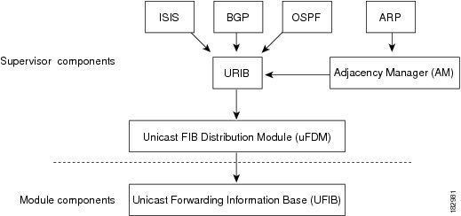
The Cisco NX-OS forwarding architecture is responsible for processing all routing updates and populating the forwarding information to all modules in the chassis.
Unicast RIB exists on the active supervisor module of forwarding architecture that maintains
the routing table with directly connected routes
static routes
routes learned from dynamic unicast routing protocols
collects adjacency information from sources such as the Address Resolution Protocol (ARP), and
determines the best next hop for a given route and populates the FIB by using the services of the unicast FIB Distribution Module (FDM).
The Cisco NX-OS forwarding architecture consists of multiple components, as shown in the following figure.
Each dynamic routing protocol must update the unicast RIB for any route that has timed out. The unicast RIB then deletes that route and recalculates the best next hop for that route (if an alternate path is available).
The adjacency manager exists on the active supervisor and maintains adjacency information for different protocols including ARP, Neighbor Discovery Protocol (NDP), and static configuration. The most basic adjacency information is the Layer 3 to Layer 2 address mapping discovered by these protocols. Outgoing Layer 2 packets use the adjacency information to complete the Layer 2 header.
The adjacency manager can trigger ARP requests to find a particular Layer 3 to Layer 2 mapping. The new mapping becomes available when the corresponding ARP reply is received and processed. For IPv6, the adjacency manager finds the Layer 3 to Layer 2 mapping information from NDP. For more information, see IPv6 Addresses.
The unicast forwarding distribution module (FDM) exists on the active supervisor that
distributes the forwarding path information from the unicast RIB and other sources
programs the forwarding information that the unicast RIB generates into the hardware forwarding tables on the standby supervisor and the modules, and
downloads the forwarding information base (FIB) information to newly inserted modules.
The unicast FDM gathers adjacency information, rewrite information, and other platform-dependent information when updating routes in the unicast FIB. The adjacency and rewrite information consists of interface, next hop, and Layer 3 to Layer 2 mapping information. The interface and next-hop information is received in route updates from the unicast RIB. The Layer 3 to Layer 2 mapping is received from the adjacency manager.
The unicast Forwarding Information Base (FIB) exists on supervisors and switching modules that
builds the information used for the hardware forwarding engine
receives route updates from the unicast FIB Distribution Module (FDM) and sends the information to the hardware forwarding engine, and
controls the addition, deletion, and modification of routes, paths, and adjacencies.
Unicast FIBs are maintained on a per-VRF and per-address-family basis. Each VRF is configured with one unicast FIB for IPv4 and one for IPv6. Based on route update messages, the unicast FIB maintains a per-VRF prefix and next-hop adjacency information database. The next-hop adjacency data structure contains the next-hop IP address and the Layer 2 rewrite information. Multiple prefixes could share a next-hop adjacency information structure.
Cisco NX-OS supports distributed packet forwarding. The ingress port takes relevant information from the packet header and passes the information to the local switching engine. The local switching engine does the Layer 3 lookup and uses this information to rewrite the packet header. The ingress module forwards the packet to the egress port. If the egress port is on a different module, the packet is forwarded using the switch fabric to the egress module. The egress module does not participate in the Layer 3 forwarding decision.
You also use the show platform fib or show platform forwarding commands to display details on hardware forwarding.
The software forwarding path in Cisco NX-OS is used mainly to handle features that are not supported in the hardware or to handle errors encountered during the hardware processing. Typically, packets with IP options or packets that need fragmentation are passed to the CPU on the active supervisor. All packets that should be switched in the software or terminated go to the supervisor. The supervisor uses the information provided by the unicast RIB and the adjacency manager to make the forwarding decisions. The module is not involved in the software forwarding path.
Software forwarding is controlled by control plane policies and rate limiters. For more information, see the Cisco NX-OS 9000 Series NX-OS Security Configuration Guide.
This section provides a brief introduction to the Layer 3 unicast features and protocols supported in Cisco NX-OS.
Layer 3 uses either the IPv4 or IPv6 protocol. IPv6 increases the number of network address bits from 32 bits (in IPv4) to 128 bits. For more information, see IPv4 Addresses or IPv6 Addresses.
IP Services include Dynamic Host Configuration Protocol (DHCP) and Domain Name System (DNS Client) clients. For more information, see Configuring DNS.
The Open Shortest Path First (OSPF) protocol is a link-state routing protocol used to exchange network reachability information within an autonomous system.
Each OSPF router advertises information about its active links to its neighbor routers. Link information consists of the link type, the link metric, and the neighbor router that is connected to the link. The advertisements that contain this link information are called link-state advertisements. For more information, see OSPFv2.
The Enhanced Interior Gateway Routing Protocol (EIGRP) is a unicast routing protocol that has the characteristics of both distance vector and link-state routing protocols.
It is an improved version of IGRP, which is a Cisco proprietary routing protocol. EIGRP relies on its neighbors to provide the routes. It constructs the network topology from the routes advertised by its neighbors, similar to a link-state protocol, and uses this information to select loop-free paths to destinations. For more information, see EIGRP.
The Intermediate System-to-Intermediate System (IS-IS) protocol is an intradomain Open System Interconnection (OSI) dynamic routing protocol specified in the International Organization for Standardization (ISO) 10589. The IS-IS routing protocol is a link-state protocol. IS-IS features are as follows:
Hierarchical routing
Classless behavior
Rapid flooding of new information
Fast Convergence
Very scalable
For more information, see Configure IS-IS.
The Border Gateway Protocol (BGP) is an inter-autonomous system routing protocol. A BGP router advertises network reachability information to other BGP routers using Transmission Control Protocol (TCP) as its reliable transport mechanism.
The network reachability information includes the destination network prefix, a list of autonomous systems that needs to be traversed to reach the destination, and the next-hop router. Reachability information contains additional path attributes such as preference to a route, origin of the route, community and others.
The Routing Information Protocol (RIP) is a distance-vector protocol that uses a hop count as its metric.
RIP is widely used for routing traffic in the global Internet and is an Interior Gateway Protocol (IGP), which means that it performs routing within a single autonomous system. For more information, see Configure RIP.
Static routing allows you to enter a fixed route to a destination.
This feature is useful for small networks where the topology is simple. Static routing is also used with other routing protocols to control default routes and route distribution. For more information, see Configuring Static Routing.
Virtualization allows you to share physical resources across separate management domains. Cisco NX-OS supports Layer 3 virtualization with virtual routing and forwarding (VRF).
VRF provides a separate address domain for configuring Layer 3 routing protocols. For more information, see Configuring Layer 3 Virtualization.
The Route Policy Manager provides a route filtering capability in Cisco NX-OS. It uses route maps to filter routes distributed across various routing protocols and between different entities within a given routing protocol. Filtering is based on specific match criteria, which is similar to packet filtering by access control lists. For more information, see Configuring Route Policy Manager.
Policy-based routing uses the Route Policy Manager to create policy route filters. These policy route filters can forward a packet to a specified next hop based on the source of the packet or other fields in the packet header. Policy routes can be linked to extended IP access lists so that routing might be based on protocol types and port numbers. For more information, see Configuring Policy-Based Routing.
First hop redundancy protocols (FHRP), such as the Hot Standby Router Protocol (HSRP) and the Virtual Router Redundancy Protocol (VRRP), allow you to provide redundant connections to your hosts.
If an active first-hop router fails, the FHRP automatically selects a standby router to take over. You do not need to update the hosts with new IP addresses because the address is virtual and shared between each router in the FHRP group. For more information on HSRP, see Configuring HSRP. For more information on VRRP, see Configure VRRP.
Object tracking allows you to track specific objects on the network, such as the interface line protocol state, IP routing, and route reachability, and take action when the tracked object’s state changes.
This feature allows you to increase the availability of the network and shorten the recovery time if an object state goes down. For more information, see Configuring Object Tracking.
| Feature Name | Feature Information |
|---|---|
|
Layer 3 features |
Cisco NX-OS 9000 Series NX-OS Multicast Routing Configuration Guide Cisco Cisco NX-OS 9000 Series NX-OS High Availability and Redundancy Guide Exploring Autonomous System Numbers: https://www.iana.org/numbers |
 Feedback