Accelerated TCP Engine (ATE)
The Accelerated TCP Engine (ATE) is a hybrid SW/HW TCP transmit engine that allows user logic to generate TCP frames from hardware, and operates in "0" clock cycles. It is currently only available for the Cisco Nexus SmartNIC+ V5P (SmartNIC+ V5P) on the "full" FDK.
ATE implements a part of TCP in conjunction with exasock, the kernel bypass library for Cisco Nexus SmartNIC (formerly ExaNIC) cards. The software establishes a TCP connection and continues to provide the relevant connection state information to the firmware. Header generation, checksum calculation, as well as send and ack sequence numbers are thus handled internally by ATE without the involvement of custom user firmware or software. Compared to TCP acceleration systems where hardware and software must operate in lock-step to regenerate headers after each transmitted packet, ATE alleviates much of the implementation difficulties as well as data transfer overhead.
ATE is designed to provide the lowest latency and smallest device footprint possible. The firmware only contains logic that is strictly necessary to send frames back-to-back at the lowest latency. Connection establishment, teardown, input handling, ACK handling, and windowing are all performed in software. As a result, ATE adds no additional latency over the standard TX MAC interface and requires roughly 1300 LUTs, 9 block rams and an Ultraram for a single port capable of 512 independent connections.
There are several limitations with the current release of ATE. Users should familiarize themselves with these before developing with ATE.
Features
- Simple software and hardware interfaces
- Tick-to-trade performance: 33ns minimum, 40ns median, 46ns maximum
- Robust TCP implementation
- 512 independent connections supported per port
- TCP payload injection from software
Prerequisite
Before using ATE, please first make sure that link is active on the ATE-enabled port and networking is set up properly. Please verify that the hosts can ping each other successfully through the ATE-enabled port.
Software Installation
ExaNIC software version 2.3.0 or greater is required to use ATE. Packages are made available for Red Hat, CentOS, Fedora and Ubuntu, and an installation from source is also possible. For more details, please see the section of the installation relevant to your situation.
The function exasock_version_text() can be called to check the currently installed version of exasock.

Note The 2.3.0 release available through the package management systems in the aforementioned Linux distributions contains a version of the exanic-benchmarker-stac-t0 demo application intended for an earlier version of ATE. While the driver and the libraries are compatible with the current ATE release, please use the open-source version on GitHub or a later ExaNIC software release in order to run the STAC-T0 benchmarker.
For information about other software requirements, see the Installation section in the SmartNIC FDK documentation.
Additional Firmware Build Parameters
ATE uses the same build system as normal FDK packages. Please refer to the Build system section in the SmartNIC FDK documentation.
An additional parameter, TCP_ENABLES, is required to instantiate ATE for ports on the SmartNIC. It is the decimal value of a bitmask, and each bit controls whether ATE is active on the corresponding port. For example, passing 1 for TCP_ENABLES enables ATE for port 0 only, 3 for ports 0 and 1, and the following instantiates ATE for all 8 interfaces:
$ make TARGET=my_app TCP_ENABLES=255 PLATFORM=v5p VARIANT=full_ate_fastmac
The top level design source of an ATE project must take the generic parameter TCP_ENABLES. The TCP_ENABLES option specified at build time is passed to the user firmware through this parameter. The code below is the module declaration of an example ATE user firmware:
module top_level
# (
    parameter MY_OTHER_PARAM = 0,
    /* This parameter must be defined */
    parameter TCP_ENABLES = 0
)
(
    /* native mode clocks, host and net data streaming busses,
     * ATE payload metadata signals, etc */
);
NoteIf ATE is enabled on a port, it is no longer possible to manipulate host RX stream or to send regular raw frames on that port. Please refer to the "Limitations" section for details.
For an ATE project, the app_ports array in the config.tcl file should contain net_tx_tcp in order to connect ATE signals into the user firmware.
ATE Example Applications
ATE-enabled FDK packages contain the example designs tcp_trigger_example and stac_t0 in addition to normal FDK examples.
tcp_trigger_example is similar to native_trigger_example. It sends a TCP packet from port 1 on receiving an ethernet frame from port 0 if the first four bytes of the destination MAC address are 0xffffffff. ATE must be instantiated on port 1, that is, bit 1 in the TCP_ENABLES bitmask must be set.
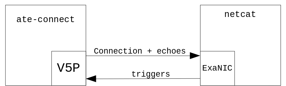
stac_t0 implements the Stack Under Test side of the STAC-T0 benchmark as defined by Securities Technology Analysis Centre (STAC). It receives simulated UDP market data though odd-numbered ports and sends out simulated TCP order responses from even-numbered ports when the STAC-T0 trigger condition is met. The external test harness generates the UDP trigger packets and measures the time elapsed between sending the UDP triggers and receiving the TCP responses. ATE must be instantiated on each even-numbered port that is intended to be part of the STAC-T0 latency test.
Running the Example Applications
The sections below contain instructions on how to run the ATE example designs. For the next steps, the following applications from ExaNIC software will be used:
example/exasock/ate-connect: this utility demonstrates establishing an ATE-accelerated connection from softwareexample/exanic/exanic_measure: this utility is a multi-purpose SmartNIC benchmarking toolexample/exanic/exanic-benchmarker-stac-t0: this utility implements the STAC-T0 test harness
Hardware Requirements:
- 2x separate Linux hosts
- 1x SmartNIC+ V5P running ATE firmware
- 1x Cisco Nexus SmartNIC K35-S (formerly X10)
- 1x QSFP-SFP breakout cable
Setting Up the Test Environment
To begin, install the SmartNIC+ V5P and the SmartNIC K35-S (X10) in separate hosts. Then connect the SmartNIC+ V5P and the SmartNIC K35-S (X10) via the QSFP-SFP breakout cable. The QSFP end needs to be connected to the bottom QSFP cage on the SmartNIC+ V5P, and the SFP end to both ports of the SmartNIC K35-S (X10). For this example, port 0 of the SmartNIC+ V5P needs to be connected to port 0 of the SmartNIC K35-S (X10), and port 1 to port 1.
Building the Demo Firmware
To build an example design, first set up the environment variables required to launch Vivado (change path to suit):
$ source /opt/Xilinx/Vivado/2017.4/settings64.sh
Then extract the FDK package and navigate to the resulting directory and type:
$ make TARGET=<fdk example design> TCP_ENABLES=<bitmask> PLATFORM=v5p VARIANT=full_ate_fastmac
Pass in stac_t0 or tcp_trigger_example for <fdk example deisgn> and pass in the appropriate decimal value of the TCP_ENABLES mask for each FDK example. The build system will then invoke Vivado to implement the design and create the bitstream exanic_v5p_stac_t0.fw or exanic_v5p_tcp_trigger_example.fw in the outputs directory. Please use this bitstream for the following steps.
Configuring the Hosts
-
The SmartNIC K35-S (X10) should be running the native NIC firmware provided by Cisco. The SmartNIC+ V5P must be running the firmware built in the last steps. The utility
exanic-fwupdatecan be used to flash both of these images onto each SmartNIC. -
Assign IP addresses to all four interfaces involved in the test, and ensure that traffic can flow between these interfaces via
ping. Below is an example set-up:--- V5P Host --- Device exanic0: Hardware type: ExaNIC V5P Port 0: IP address: 10.10.0.50 Mask: 255.255.255.0 Port 1: IP address: 10.10.1.51 Mask: 255.255.255.0 --- X10 Host --- Device exanic0: Hardware type: ExaNIC X10 Port 0: IP address: 10.10.0.100 Mask: 255.255.255.0 Port 1: IP address: 10.10.1.101 Mask: 255.255.255.0
Running the tcp_trigger_example Demo Application
-
On the SmartNIC+ V5P host, use
exanic-fwupdateto flash theexanic_v5p_tcp_trigger_example.fwbitstream into the SmartNIC+ V5P. Hot-reload or reboot the host so the firmware comes into effect. -
On the SmartNIC K35-S (X10) host, run a TCP server.
root@X10host:~# nc -lk -p 5000 -
On the SmartNIC+ V5P host, use
ate-connectwithexasockto establish a hardware-accelerated TCP connection to the SmartNIC K35-S (X10) host routed through SmartNIC+ V5P port 1:root@V5Phost:~# make -C exanic-software/examples/exasock root@V5Phost:~# exasock exanic-software/examples/exasock/ate-connect 10.10.1.101 5000 -
On the SmartNIC K35-S (X10) host, run
exanic_measurein raw mode:root@X10host:~# make -C exanic-software/example/exanic root@X10host:~# exanic-software/examples/exanic/exanic_measure -d exanic0 -p 0 -P 1 -R
exanic_measure accepts the -O parameter to subtract a fixed value from the latency figures. This is done to correct for the latency incurred by cables and other external devices and the value used can be measured using exanic_measure in raw mode as well.
Below is the expected latency result reported by exanic_measure after the external latency has been correctly compensated for:
Average: 39.70
Percentile 100.00 = 46.25 ns
Percentile 99.00 = 46.00 ns
Percentile 95.00 = 42.50 ns
Percentile 90.00 = 42.25 ns
Percentile 75.00 = 41.75 ns
Percentile 50.00 = 40.50 ns
Percentile 25.00 = 39.50 ns
Percentile 10.00 = 34.75 ns
Percentile 5.00 = 34.00 ns
Percentile 1.00 = 33.50 ns
Percentile 0.00 = 33.25 ns
Running the stac_t0 Demo Application
NoteThe stac_t0 example design requires either the GitHub version of ExaNIC software or a release after 2.3.0.
-
On the V5P host, use
exanic-fwupdateto flash theexanic_v5p_stac_t0.fwbitstream into the SmartNIC+ V5P. Hot-reload or reboot the host so the firmware comes into effect. -
On the SmartNIC K35-S (X10) host, run a TCP server. For this example,
netcatcan be used.root@X10host:~# nc -lk -p 5000 -
On the SmartNIC+ V5P host, use
ate-connectwithexasockto establish a hardware-accelerated TCP connection to the SmartNIC K35-S (X10) host routed through SmartNIC+ V5P port 0:root@V5Phost:~# make -C exanic-software/examples/exasock root@V5Phost:~# exasock exanic-software/examples/exasock/ate-connect 10.10.0.100 5000 -
On the SmartNIC K35-S (X10) host, run the stac-t0 benchmarker:
root@X10host:~# make -C exanic-software/examples/exanic
root@X10host:~# exanic-software/examples/exanic/exanic-benchmarker-stac-t0 -d exanic0 -M A -p 1 -P 0 -c 10000
exanic-benchmarker-stac-t0 will output TX (UDP trigger) and RX (TCP echo) packets to the specified save file (see step 4) for further analysis. It will be of the following format:
[RX|TX] [packet-order] [STAC T0 index] [HW timestamp]
The standard triggering frequency of the STAC-T0 test is 1 in 1024. In the above example, 10,000 trigger packets are sent into SmartNIC+ V5P port 1, thus around 10 TCP echos (i.e. RX packets) are expected from SmartNIC+ V5P port 0.
Additionally, exanic-benchmarker-stac-t0 accepts the -H option to mask the trigger packets in a way such that a TCP echo is expected for every trigger. In that case the expected number of RX packets would be 10,000.
Development
Software
ATE is intended to be used with exasock version 2.3.0 or later. Besides an extra step before connection establishment, all other operations are performed using the standard socket API.
ATE can only be used with an actively opened connection: accelerating a passively-opened connection established by calling accept on a listening socket is not supported.
Connection Establishment
In order to enable ATE for a TCP connection, a setsockopt call is needed before connection establishment to enable hardware acceleration for the connection and to set the ATE connection ID. The following code is an example of establishing an ATE-accelerated connection in software:
// SOL_EXASOCK and SO_EXA_ATE
#include <exasock/socket.h>
...
int fd = socket(AF_INET, SOCK_STREAM, 0);
int ate_id = 0;
if (setsockopt(fd, SOL_EXASOCK, SO_EXA_ATE, &ate_id, sizeof(ate_id)) == -1)
{
    perror("Failed to enable ATE");
    // handle failure
}

if (connect(fd, (struct sockaddr *)&sa, sizeof sa) == -1)
{
    perror("Failed to connect to server");
    // handle error
}
Alternatively, exasock provides the function exasock_ate_connect, a helper function that combines both operations.
// exasock_ate_connect
#include <exasock/socket.h>
...
int fd = socket(AF_INET, SOCK_STREAM, 0);
int ate_id = 0;

if (exasock_ate_connect(fd, ate_id, (struct sockaddr *)sa, sizeof sa))
{
    perror("Failed to establish ATE-accelerated connection");
    // handle error
}
Transmitting Packets
Once ATE is enabled for a socket, system calls such as send and write cause data to be transmitted through ATE.
Transmitting raw ethernet frames by directly using libexanic functions such as exanic_transmit_frame is still possible. In this case, ATE is not involved in sending the frame.
NoteSoftware TCP payload and raw frame injection should not be used for performance-sensitive tasks, as ATE is not optimised for this use case.
Receiving Packets
This is done in exactly the same manner as a conventional TCP connection, using system calls such as read and recv.
Firmware
The hardware interface consists of TCP payload streaming signals and metadata signals.
The ATE data streaming interface uses the same interface signals as the standard TX MAC interface, namely tx_data_net, tx_sof_net, tx_eof_net, tx_len_net and tx_ack_net For this reason, sending raw frames from user firmware is not possible through an ATE-enabled port.
The metadata signals consist of payload_length, payload_csum, payload_conn_id and window_available.
All signals are in the native TX 322MHz clock domain. Host and dual clocking modes are not available when using ATE.
Data Streaming Signals
For more information on the streaming interface, see the "Network interface" subsection in the SmartNIC FDK documentation.
tx_data_net(output, 32 bits)tx_sof_net(output, 1 bit)tx_eof_net(output, 1 bit)tx_len_net(output, 2 bits)tx_ack_net(input, 1 bit)
Asserting tx_sof_net causes ATE to begin attempting to switch internal bus arbiters over to allow the user firmware to send a TCP packet. If ATE is not in the middle of transmitting a software-injected raw frame or TCP segment, this step occurs in the same clock cycle that tx_sof_net is asserted, and ATE will begin transmitting the protocol headers. tx_ack_net will be asserted once ATE has finished transmitting the headers and is ready to accept TCP payload bytes.
The timing diagrams below illustrate the timing relationships between the data streaming signals.
Payload Metadata Signals
In order to achieve 0-cycle latency, there are some timing requirements between the metadata signals and the data streaming signals.
The metadata signals and the aforementioned requirements are detailed below:
payload_conn_id(output, 16 bits): ATE connection ID of the packet being sent. Must be valid at least a cycle beforetx_sof_net.payload_length(output, 16 bits): the length of the payload transmitted. Must be valid by the 3rd cycle aftertx_sof_net.window_available(input, 1 bit): informs the user firmware whether the next attempt to send data will stay within the TCP window size as defined by the peer's advertised receive window and the host's congestion control window values. Also used to indicate whether the software has enabled hardware payload injection for the current connection. Set up bypayload_lengthandpayload_conn_idand is valid two cycles after either changes. Advisory only, attempting to transmit data whilewindow_availableis low will still succeed.payload_csum(output, 32 bit): the result of applying the TCP checksum algorithm to the payload only, without the pseudo-header, and omitting the final step of ones-complementing the result. Must be valid by the 9th cycle aftertx_sof_net.
NoteDue to implementation details internal to ATE, the user application is required to swap the most significant byte and the least significant byte in each 16-byte word of payload when performing partial checksum calculation. If an odd number of bytes is to be sent, then the final byte must be added without padding the least significant byte with 00h; see tcp_responder.v from the STAC T0 example.
Analogous to the requirement that sof, eof and len remain stable until ack is asserted, the payload metadata signals must also remain stable after the deadlines until header generation is completed and tx_ack_net is asserted, after which they are no longer required to remain in their previous states.
For a worked example of payload checksum calculation, consider sending 7 bytes: 0xAB, 0xCD, 0xEF, 0xCA, 0xDB, 0xEC, 0xAD. Grouped into 16-bit words, in network byte order, and zero-padded after the final byte according to RFC 793:
0xABCD, 0xEFCA, 0xDBEC, 0xAD00
Swapping the bytes within each 16-bit word and calculating the 2's compliment sum:
   0xCDAB
   0xCAEF
   0xECDB
 + 0x00AD
----------
  0x28631
Then, adding the overflow to the lower 16 bits and truncating, the value for payload_csum is 0x8633.
Note that the final value put in the payload_csum signal can be of either one of the two formats:
- the 16-bit 1's complement sum of all the 16-bit data words, stored in the 16 least significant bits, with the upper 16 bits set to 0. For the example above, this would be 32'h00008633
- or, the 32 bit 2's complement sum of all the 16-bit data words in the least significant bits. For the example above, this would be 32'h00028631.
It does not matter which representation of the checksum is used because ATE folds the upper 16 bits into the lower 16 bits during the final checksum calculation, so both formats result in the same checksum. However, we recommend the 32 bit 2's complement format. This will be faster to compute as the user code can avoid folding the upper 16 bits into the lower 16-bit sum to produce the 1's complement value, saving an addition.
Advice for Fast Checksum Calculation
As fast checksum calculation is likely to be the bottleneck of the system, we suggest the following optimisations:
-
A pipelined tree of adders can be used to sum the payload words. With respect to the above example, choosing a maximum fan-in of two, checksum computation can be completed in three clock cycles: in the first stage, with 4 adders, the 4-byte words are collapsed into 4 partial sums; in the second stage, with 2 adders, two partial sums are produced; and finally the payload checksum is available in the third cycle. The number of cycles is logarithmic in the payload length and decreases as maximum fan-in level increases.
-
Only sum the words which change from packet to packet. Most protocols consist largely of static data along with a few fields which are set on the fly. The checksum of the static data can be calculated beforehand and the user firmware only needs to sum over the dynamic fields in the latency-critical path.
Timing Diagrams
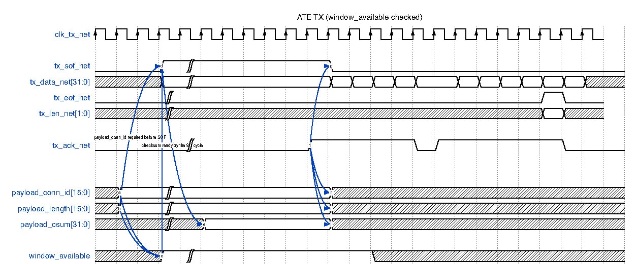
The diagram above illustrates the timing relationship between ATE interface signals if the user chooses to check the window_available signal.
!!! Note:
- `payload_conn_id` is set up before `tx_sof_net`
- `payload_csum` is computed by the 9th cycle after `tx_sof_net`
- Metadata signals are stable after their respective dealines and before `tx_ack_net` is asserted
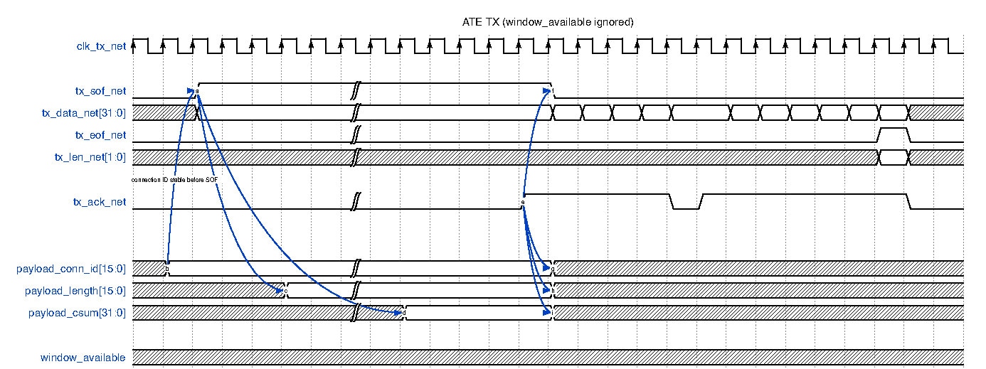
The diagram above illustrates the timing requirements if the user chooses to ignore window_available.
!!! Note:
- `payload_conn_id` should still lead `tx_sof_net` by at least a cycle
- `payload_length` is only required the 3rd cycle after `tx_sof_net`
Limitations
The current ATE release has the following limitations. We expect to resolve these limitations in a future version.
- ATE does not support VLAN-tagged interfaces. Data sent through a socket bound to a VLAN-tagged interface with ATE enabled will not have the VLAN header fields.
- If a DMA channel is used by ATE, it is not available to the user firmware. The
rx_*_hostbus driven from the user firmware will have no effect. - Sending regular raw packets (i.e. without the TCP header) from user firmware is not possible on a port if ATE is instantiated. This is due to the fact that the
tx_*_netbus, which is connected to the TX MAC if ATE is not instantiated, is repurposed for streaming TCP payload bytes instead.
Troubleshooting
exasock_ate_connect(alsosetsockopt(SOL_EXASOCK, SO_EXA_ATE)) can return withENOPROTOOPT("protocol not available") if support for ATE is not loaded (for example, by using an exasock version before ATE, a firmware image without ATE, or a SmartNIC FDK unlock key that does not have ATE enabled)- When building an ATE firmware, please make sure to supply the
TCP_ENABLESparameter as described in the section Additional firmware build parameters.
 Feedback