Cisco Nexus Dashboard Deployment and Upgrade Guide, Release 4.3.x
Bias-Free Language
The documentation set for this product strives to use bias-free language. For the purposes of this documentation set, bias-free is defined as language that does not imply discrimination based on age, disability, gender, racial identity, ethnic identity, sexual orientation, socioeconomic status, and intersectionality. Exceptions may be present in the documentation due to language that is hardcoded in the user interfaces of the product software, language used based on RFP documentation, or language that is used by a referenced third-party product. Learn more about how Cisco is using Inclusive Language.
Deploying a Virtual Nexus Dashboard (vND) in Nutanix
Prerequisites and guidelines for deploying vNDs in Nutanix
You can now deploy virtual Nexus Dashboard (vNDs) on Nutanix Hyperconverged Infrastructure (HCI).
Before you proceed with deploying vNDs in Nutanix, you must follow these prerequisites and guidelines.
vNDs on Nutanix supports both single-node and three-node deployments. The underlying Nutanix cluster can be of any size, provided
that it has sufficient resources to host the required nodes and workload.
Scale support and co-hosting vary based on the cluster form factor. Use the Nexus Dashboard Capacity Planning tool to verify that the virtual form factor satisfies your deployment requirements.
Management and data interfaces must be created with subnets of the same type, where both subnets are either VLAN Basic or VLAN. Deployment of vND in Nutanix will fail if different subnet types are used for management and data interfaces.
The CPU family used for the Nexus Dashboard VMs must support the AVX instruction set.
The Nutanix node must have enough system resources, and the Nutanix system storage device must have I/O latency under 20ms.
See Understanding system resources for more information on system resources. Only 1-node (data) and 3-node (data) virtual profiles are supported. You must explicitly
reserve these resources on each node to achieve maximum performance and reliability.
When you deploy a Nexus Dashboard cluster on Nutanix Hyperconverged Infrastructure (HCI), the Nutanix storage device must
have a latency under 20ms. This is done in the Performance Validation step if you use the kvm_deployer deployment script for QCOW2 images, as described in About the deployment script for QCOW2 images.
Follow these steps if you want to manually verify the I/O latency of a Nutanix storage device.
After you use the command, confirm that the 99.00th=[value] in the fsync/fdatasync/sync_file_range section is under 20ms.
Understanding system resources
When deploying a Nexus Dashboard cluster in Nutanix, you must verify that you have enough system resources. There are multiple
form factors supported when deploying a Nexus Dashboard cluster in Nutanix, and the amount of system resources needed for
each node differs based on the form factor.
Note
Deployment of virtual Nexus Dashboard (vNDs) in Nutanix is supported only on data nodes, as shown below. Deployment of vNDs
in Nutanix is not supported on app nodes.
Nexus Dashboard supports KVM virtualization across various environments, including RHEL and Nutanix. Nexus Dashboard deployments
are typically done using QCOW2 images; however, the diversity of KVM variants and host configurations creates challenges in
tracking supported versions and ensuring optimal device emulation for performance.
The deployment script for QCOW2 images addresses these challenges by providing a deployment validation and orchestration script
that is packaged with the QCOW2 image. This script is designed to streamline the deployment process, ensure compatibility,
and help maintain consistent performance standards across supported platforms.
Key Features
These are the key features for the deployment script for QCOW2 images:
Platform Compatibility Check:Verifies that the underlying host operating system is a supported distribution and version.
Resource Validation: Assesses whether the host meets minimum compute requirements, including CPU, memory, and storage resources.
Performance Validation:
Disk I/O and Network Latency: Measures key performance indicators such as disk I/O and network I/O latency, ensuring they fall within qualified ranges.
Device Emulation: Confirms that the correct device emulation (such as network interfaces and virtual disk devices) is available for optimal
performance.
Deployment Orchestration: Automates the deployment process for both single-node and multi-node clusters, orchestrating virtual machines with the appropriate
device mappings (such as network and storage devices).
Because storage is the most common bottleneck, the script categorizes storage into "Performance Tiers":
Disk Type & Placement (SSD/NVMe): Validates for high-IOPs workloads.
RAID vs. JBOD: Validates write speed.
Remote Storage (iSCSI/FC/NFS): Performs a "Pre-Flight Latency Check":
Sync Latency: Must be < 10ms for standard apps and < 1ms for high-performance databases.
IOPS Validation: Uses a temporary fio test to ensure the required IOS.
Prerequisites for the deployment script for QCOW2 images
These are the prerequisites before using the deployment script for QCOW2 images.
Requirement
Details
Nutanix Prism Central
Reachable on port 9440 (HTTPS) from the machine running the deployer
Nutanix Prism Element
Reachable on port 9440 (HTTPS); used for storage, networking, and VM console access
Prism credentials
A user account with permissions to create images, list subnets, and manage VMs
ND qcow2 image
A local path to the Nexus Dashboard .qcow2 image file
Network info
Subnet name(s) configured in Prism, and 3 management IPs + a gateway
Go toolchain
Go 1.22+ to build from source (or use a pre-built binary)
Understanding the differences between Prism Central and Prism Element
The deployment script uses Prism Central (PC) for all API operations — image uploads, VM creation, and lifecycle management. You will need its IP and credentials
for the configuration file.
Prism Element (PE) manages the individual Nutanix cluster and is useful for:
Viewing storage containers and disk utilization
Checking network/subnet configuration at the cluster level
Accessing the VM serial console for troubleshooting boot issues
Monitoring host-level health and hardware status
Interface
URL
When you need it
Prism Central
https://prism_central_ip:9440
Deploying, managing, and destroying VMs; uploading images; verifying subnet names
Prism Element
https://prism_element_ip:9440
Checking storage containers, network config, VM console access, host health
Use the deployment script for QCOW2 images
Procedure
Step 1
Locate the tar file with the deployment script.
The tar file should be available at the same location as the QCOW2 image. For example, in the Software Download site for Nexus Dashboard for the 4.3.1 release and later, you should see the tar file with the deployment script for QCOW2 images at the same area
as the QCOW2 image itself, such as this:
nd-dk9.4.3.1.175.qcow2.tar.gz
Step 2
Download the tar file with the deployment script.
Step 3
Extract the tar file.
For example:
tar -xzvf nd-dk9.4.3.1.175.qcow2.tar.gz
You should see output similar to the following after extracting the tar file and listing the contents in the directory:
#ls -lrt
total 24730576
-rwxr-xr-x 1 root root    35991736 May  5 23:35 kvm_deployer
-rw-r--r-- 1 root root 12651498496 May 17 03:44 nd-dk9.4.3.1.175.qcow2
-rw-r--r-- 1 root root 12636610743 May 18 22:44 nd-dk9.4.3.1.175.qcow2.tar.gz
Step 4
Use the kvm_deployer config command to create a yaml file to use with the deployment script.
Make the appropriate choices at each stage based on your deployment type.
For example, to generate a one-node yaml file:
# ./kvm_deployer config
Configure Nexus Dashboard deployment:
 Deployment Platform (kvm/nutanix): nutanix
 Image Path (qcow2): /home/nd-base/nd-dk9.4.3.1.175.qcow2
 Cluster Size: 1
 VM Type (app/data/large/xlarge): data
 Admin Password:
Configure Nutanix platform settings:
 Prism Central IP: 192.168.94.164
 Nutanix Username: admin
 Nutanix Password:
 Cluster Name: sit_reg1_nutanix
 Management Network Name: mgmt
 Data Network Name: data-network
 VCPUs per Socket (default: 2): (current: 0): 2
Configure VM (1) for Nutanix:
  VM Name (lowercase, numbers, dashes, max 63 chars): node1
  Management Network (e.g., 192.168.1.100/24): 192.168.94.166/24
  Management Gateway IP: 192.168.94.1
[✔] Configuration Summary:
 Deployment Platform        : nutanix
 Image Path (qcow2)         : /home/nd-base/nd-dk9.4.3.1.175.qcow2
 Admin Password             : [hidden]
 VM Type                    : data
 Nutanix Configuration:
  Prism Central IP            : 192.168.94.164
  Username                    : admin
  Password                    : [hidden]
  Cluster Name                : sit_reg1_nutanix
  Network Name                : mgmt
  VCPUs per Socket            : 2
 VMs:
  VM Name                    : node1
   Management Network         : 192.168.94.166/24
   Management Gateway IP      : 192.168.94.1
 Proceed with current config? (y/n): y
 File name to save configuration: nutanix_1node_deploy.yaml
To generate a three-node yaml file:
# ./kvm_deployer config
Configure Nexus Dashboard deployment:
 Deployment Platform (kvm/nutanix): nutanix
 Image Path (qcow2): /home/nd-base/nd-dk9.4.3.1.175.qcow2
 Cluster Size: 3
 VM Type (app/data/large/xlarge): data
 Admin Password:
Configure Nutanix platform settings:
 Prism Central IP: 192.168.94.164
 Nutanix Username: admin
 Nutanix Password:
 Cluster Name: sit_reg1_nutanix
 Management Network Name: mgmt
 Data Network Name: data-network
 VCPUs per Socket (default: 2): (current: 0): 2
Configure VM (1) for Nutanix:
  VM Name (lowercase, numbers, dashes, max 63 chars): node1
  Management Network (e.g., 192.168.1.100/24): 192.168.94.166/24
  Management Gateway IP: 192.168.94.1
Configure VM (2) for Nutanix:
  VM Name (lowercase, numbers, dashes, max 63 chars): node2
  Management Network (e.g., 192.168.1.100/24): 192.168.94.167/24
  Management Gateway IP: 192.168.94.1
Configure VM (3) for Nutanix:
  VM Name (lowercase, numbers, dashes, max 63 chars): node3
  Management Network (e.g., 192.168.1.100/24): 192.168.94.168/24
  Management Gateway IP: 192.168.94.1
[✔] Configuration Summary:
 Deployment Platform        : nutanix
 Image Path (qcow2)         : /home/nd-base/nd-dk9.4.3.1.175.qcow2
 Admin Password             : [hidden]
 VM Type                    : data
 Nutanix Configuration:
  Prism Central IP            : 192.168.94.164
  Username                    : admin
  Password                    : [hidden]
  Cluster Name                : sit_reg1_nutanix
  Network Name                : mgmt
  VCPUs per Socket            : 2
 VMs:
  VM Name                    : node1
   Management Network         : 192.168.94.166/24
   Management Gateway IP      : 192.168.94.1
  VM Name                    : node2
   Management Network         : 192.168.94.167/24
   Management Gateway IP      : 192.168.94.1
  VM Name                    : node3
   Management Network         : 192.168.94.168/24
   Management Gateway IP      : 192.168.94.1
 Proceed with current config? (y/n): y
 File name to save configuration: nutanix_3node_deploy.yaml
Step 5
(Optional) Use a text editor to verify the information saved in the yaml file, if necessary.
For example, for the three-node example above, the yaml file would have information similar to the following:
Deploying VM node1 using kvm
  Cleanup old images
  [✔] Cleaned image /home/nd-node1/boot.img
  [✔] Cleaned image /home/nd-node1/disk.img
  [✔] Cleaned image /home/nd-node1/config-drive.img
  Creating boot disk, it can take several minutes, pls wait
  [✔] Boot disk created successfully
  Creating raw disk, it can take several minutes, pls wait
  [✔] Raw disk created successfully
  Creating configuration drive
  [✔] Configuration drive created successfully

  Starting VM
  [✔] VM started successfully
[✔] KVM VM: node1 deployed successfully
Deploying VM node2 using kvm
 Copying file /home/nd-base/nd-dk9.4.3.1.175.qcow2 to /home/nd-node2/nd-dk9.4.3.1.175.qcow2
 [✔] File /home/nd-base/nd-dk9.4.3.1.175.qcow2 copied to /home/nd-node2/nd-dk9.4.3.1.175.qcow2
  Cleanup old images
  [✔] Cleaned image /home/nd-node2/boot.img
  [✔] Cleaned image /home/nd-node2/disk.img
  [✔] Cleaned image /home/nd-node2/config-drive.img
  Creating boot disk, it can take several minutes, pls wait
  [✔] Boot disk created successfully
  Creating raw disk, it can take several minutes, pls wait
  [✔] Raw disk created successfully
  Creating configuration drive
  Copying file /home/nd-node1/node2-bootstrap.json to /home/nd-node2/apic-sn-cfg-mount/bootstrap.json
  [✔] File /home/nd-node1/node2-bootstrap.json copied to /home/nd-node2/apic-sn-cfg-mount/bootstrap.json
  [✔] Configuration drive created successfully
  Starting VM
  [✔] VM started successfully
[✔] KVM VM: node2 deployed successfully
Deploying VM node3 using kvm
 Copying file /home/nd-base/nd-dk9.4.3.1.175.qcow2 to /home/nd-node3/nd-dk9.4.3.1.175.qcow2
 [✔] File /home/nd-base/nd-dk9.4.3.1.175.qcow2 copied to /home/nd-node3/nd-dk9.4.3.1.175.qcow2
  Cleanup old images
  [✔] Cleaned image /home/nd-node3/boot.img
  [✔] Cleaned image /home/nd-node3/disk.img
  [✔] Cleaned image /home/nd-node3/config-drive.img
  Creating boot disk, it can take several minutes, pls wait
  [✔] Boot disk created successfully
  Creating raw disk, it can take several minutes, pls wait
  [✔] Raw disk created successfully
  Creating configuration drive
  Copying file /home/nd-node1/node3-bootstrap.json to /home/nd-node3/apic-sn-cfg-mount/bootstrap.json
  [✔] File /home/nd-node1/node3-bootstrap.json copied to /home/nd-node3/apic-sn-cfg-mount/bootstrap.json
  [✔] Configuration drive created successfully
  Starting VM
  [✔] VM started successfully
[✔] KVM VM: node3 deployed successfully
When you run deploy, the tool performs the following steps for each of the VMs:
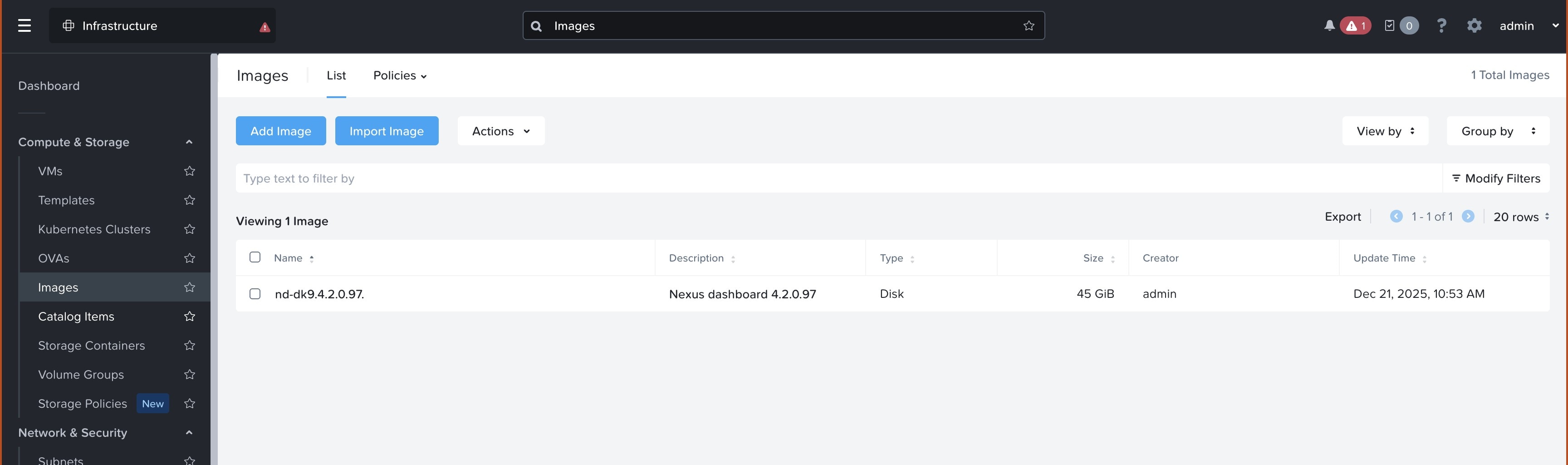
Image upload — Checks if the qcow2 image already exists in Prism Central (matched by filename). If not, uploads it and waits
until it becomes active.
Subnet resolution — Resolves network_name (and data_network_name if set) to Prism subnet UUIDs.
VM creation — Creates the VM in a powered-off state with:
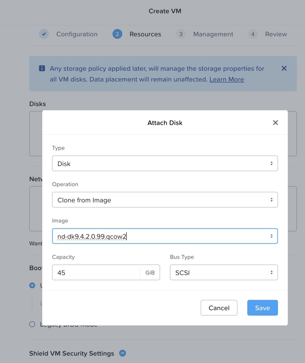
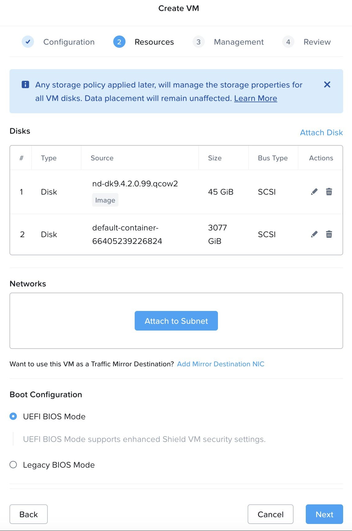
A boot disk cloned from the uploaded image
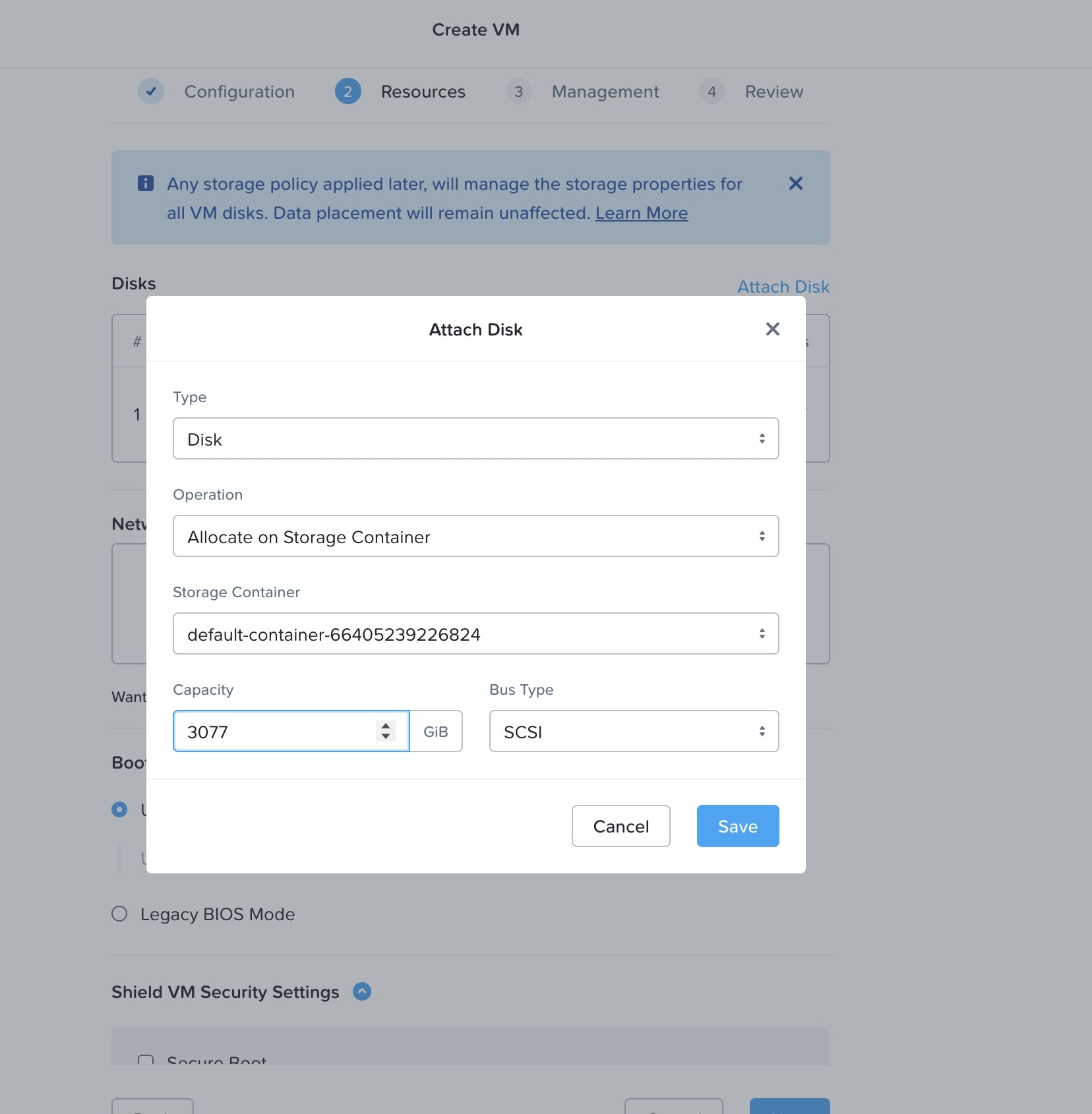
A secondary 3077 GiB raw data disk
NIC(s) attached to the resolved subnet(s)
Cloud-init user data carrying the admin password, management IP, and gateway
Power on — Powers on the VM and waits for the task to complete.
Step 7
Complete the post-deployment steps.
Cluster formation — Once all the nodes are running, complete the Nexus Dashboard cluster setup through the Nexus Dashboard UI using the management
IP addresses from your config.
Optional post-deployment tasks
Troubleshooting
Symptom
Check
Connection refused / timeout
Verify Prism Central is reachable on port 9440 from your machine
Authentication failure
Verify username and password in the config
Image upload hangs
Ensure image_path points to a valid qcow2 file and there is sufficient storage in Prism
Subnet not found
Verify network_name matches the exact subnet name shown in Prism Central
VM not getting IP
Check that cloud-init management_network uses valid CIDR notation and the gateway is correct
VM stuck at boot
Use Prism Element (https://<prism_element_ip>:9440) to open the VM serial console and check boot logs
Storage issues
Check available storage containers and disk space in Prism Element
Destroy the deployment
If you want to destroy the deployment, enter this command:
$ kvm_deployer destroy --config nutanix_3node_deploy.yaml
Destroying VM node1 using nutanix
Destroying VM node1 using nutanix
 Looking for VM: node1
 Found VM node1 with UUID: 94fe9518-5196-4807-a6cc-183d1abe760e
 Powering off VM: 94fe9518-5196-4807-a6cc-183d1abe760e
 VM power off request submitted
 Deleting VM: 94fe9518-5196-4807-a6cc-183d1abe760e
 VM deletion task submitted: 8178938b-5014-474b-b168-34c3bf5b1577
 Waiting for task completion: 8178938b-5014-474b-b168-34c3bf5b1577
  Task status: RUNNING, progress: 0%
  Task status: SUCCEEDED, progress: 100%
 [✔] Task completed successfully (status: SUCCEEDED)
 [✔] VM deleted successfully
[✔] VM node1 destroyed successfully
Destroying VM node2 using nutanix
Destroying VM node2 using nutanix
 Looking for VM: node2
 Found VM node2 with UUID: f1424251-182d-4518-9acc-f06ba89d4883
 Powering off VM: f1424251-182d-4518-9acc-f06ba89d4883
 VM power off request submitted
 Deleting VM: f1424251-182d-4518-9acc-f06ba89d4883
 VM deletion task submitted: a8d41687-3d84-4a38-91cc-5dfee0688351
 Waiting for task completion: a8d41687-3d84-4a38-91cc-5dfee0688351
  Task status: RUNNING, progress: 0%
  Task status: SUCCEEDED, progress: 100%
 [✔] Task completed successfully (status: SUCCEEDED)
 [✔] VM deleted successfully
[✔] VM node2 destroyed successfully
Destroying VM node3 using nutanix
Destroying VM node3 using nutanix
 Looking for VM: node3
 Found VM node3 with UUID: 8cdc2037-fc83-43af-90f6-869c00aa2fdc
 Powering off VM: 8cdc2037-fc83-43af-90f6-869c00aa2fdc
 VM power off request submitted
 Deleting VM: 8cdc2037-fc83-43af-90f6-869c00aa2fdc
 VM deletion task submitted: 710c58a7-0728-4c4e-b63a-f6d90e3b2669
 Waiting for task completion: 710c58a7-0728-4c4e-b63a-f6d90e3b2669
  Task status: RUNNING, progress: 0%
  Task status: SUCCEEDED, progress: 100%
 [✔] Task completed successfully (status: SUCCEEDED)
 [✔] VM deleted successfully
[✔] VM node3 destroyed successfully
$
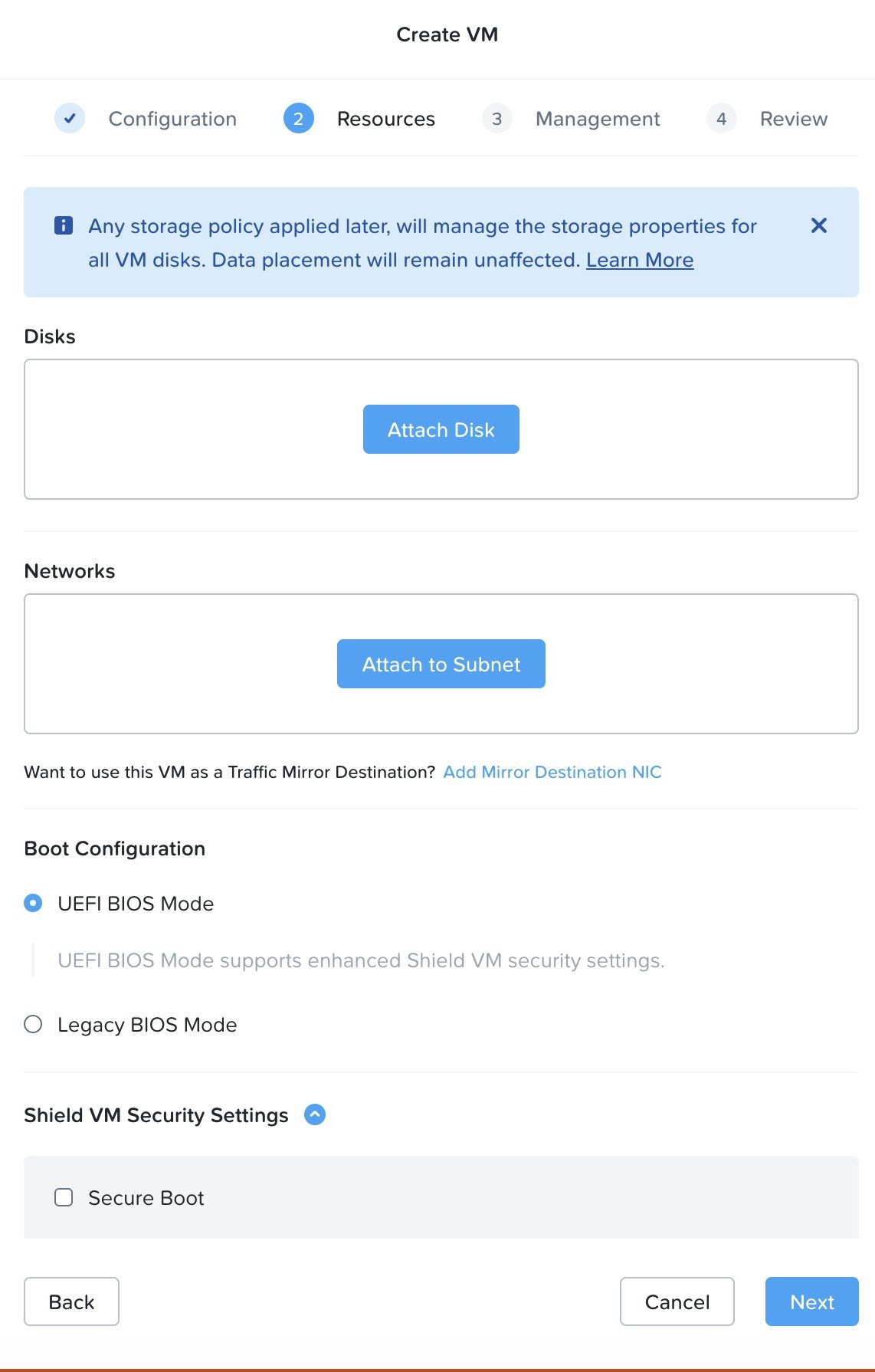
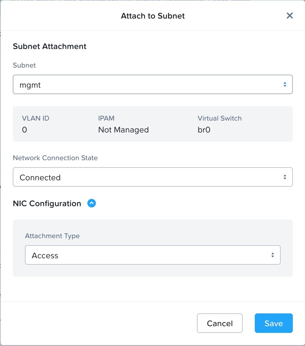
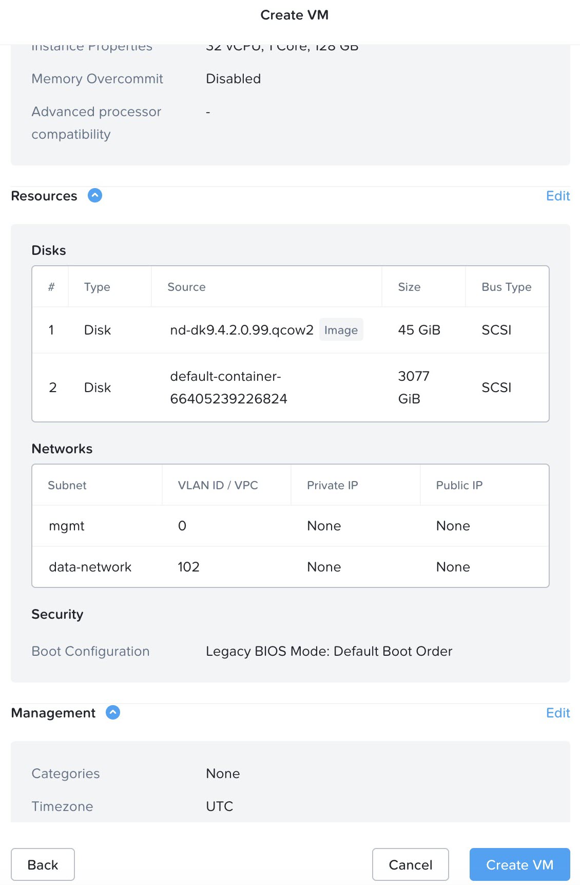
In the 2. Resources window, click Attach to Subnet and make the necessary configurations for the first subnet.
Note
Management and data interfaces must be created with subnets of the same type, where both subnets are either VLAN Basic or VLAN. Deployment of vND in Nutanix will fail if different subnet types are used for management and data interfaces.
In the Subnet field, choose the management subnet.
Configure the entry in the Attachment type field to reflect your environment.
Click Save when you have completed the configurations in this window.
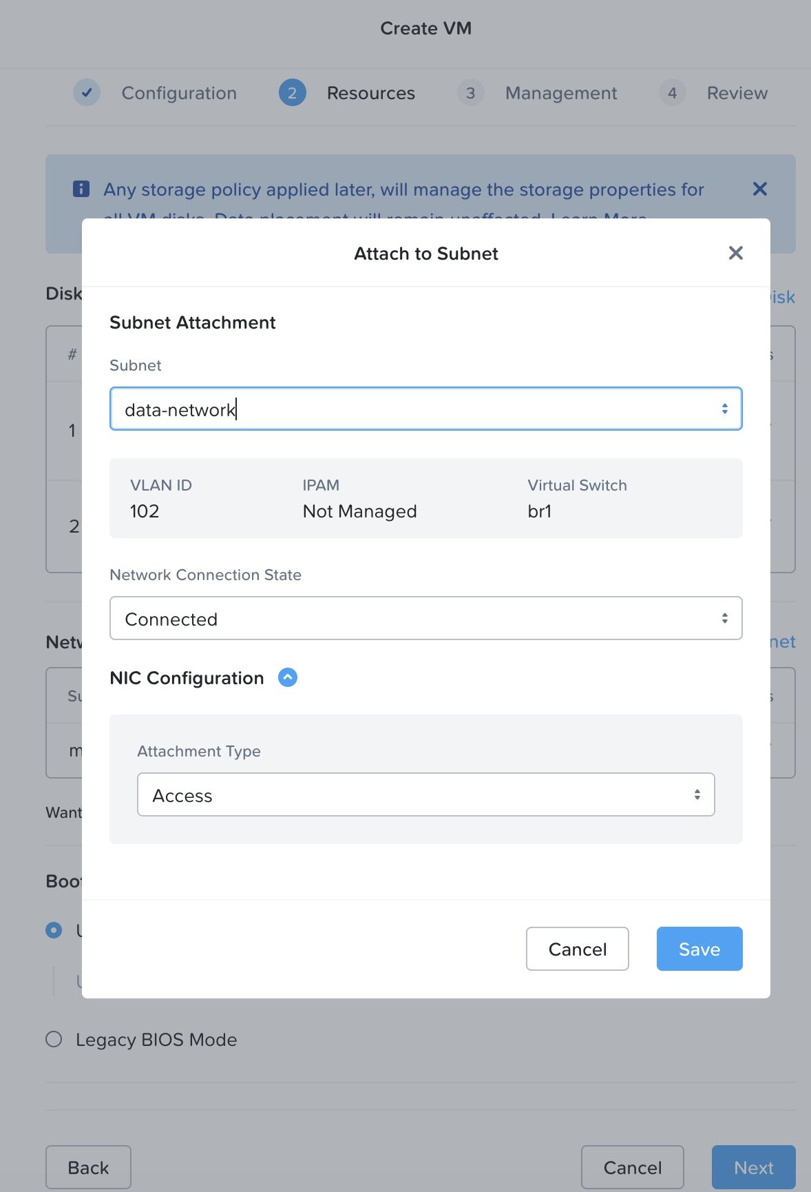
In the 2. Resources window, click Attach to Subnet and make the necessary configurations for the second subnet.
In the Subnet field, choose the data subnet.
Configure the entry in the Attachment type field to reflect your environment.
Click Save when you have completed the configurations in this window.
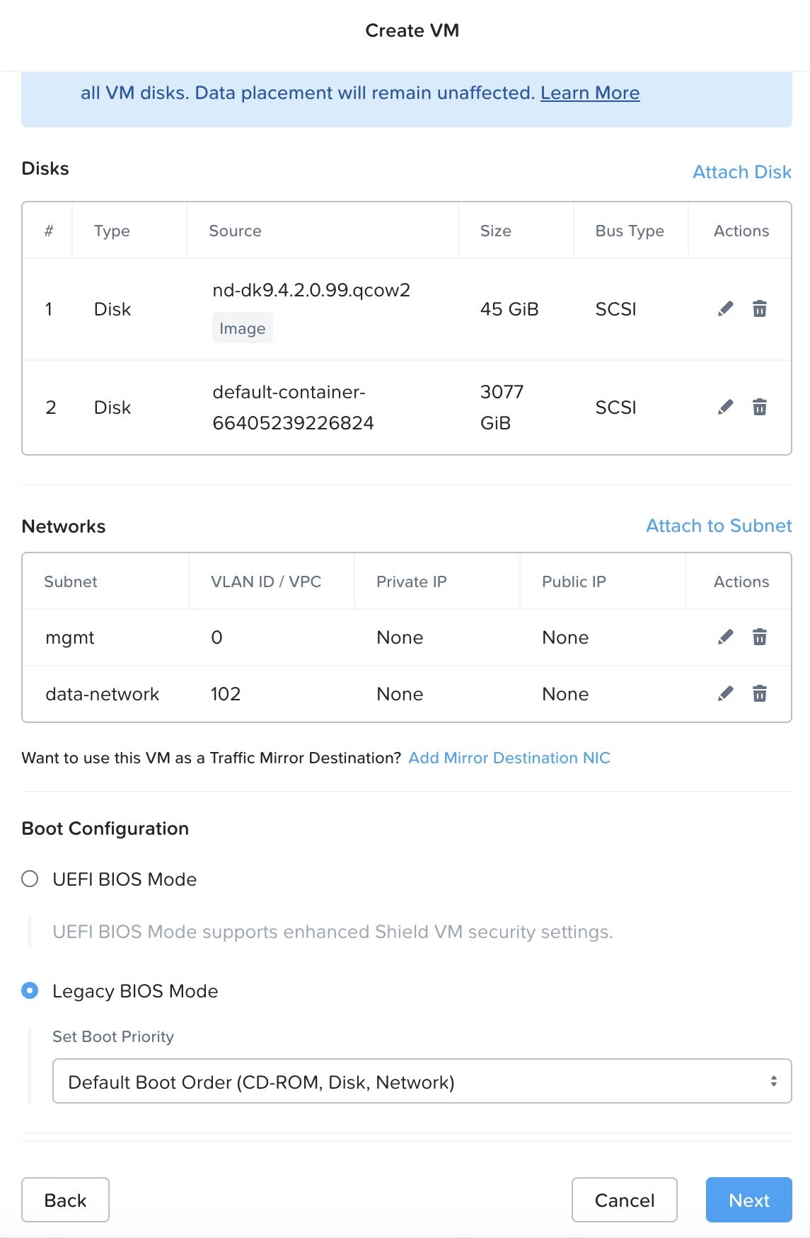
In the 2. Resources window, in the Boot Configuration area, choose Legacy BIOS Mode and confirm the choice.
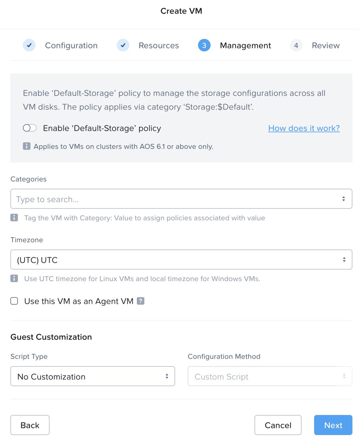
Navigate through the Management window and click Next without making changes.
Click Create VM.
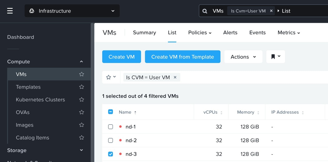
Do not power on the VM after the deployment.
If you are deploying in a 3-node cluster, repeat these steps for each Nexus Dashboard node in the cluster.
Attach a serial console to a VM.
Nexus Dashboard requires a serial port for the configuration and bootstrap. To manage and add a new serial port, log on to
any CVM CLI using SSH.
Open one of the node's console and configure the node's basic information.
Press any key to begin initial setup.
You will be prompted to run the first-time setup utility:
[ OK ] Started atomix-boot-setup.
       Starting Initial cloud-init job (pre-networking)...
       Starting logrotate...
       Starting logwatch...
       Starting keyhole...
[ OK ] Started keyhole.
[ OK ] Started logrotate.
[ OK ] Started logwatch.

Press any key to run first-boot setup on this console...
Enter and confirm the admin password
This password will be used for the rescue-user SSH login as well as the initial GUI password.
Note
You must provide the same password for all nodes or the cluster creation will fail.
Admin Password:
Reenter Admin Password:
Enter the management network information.
Management Network:
  IP Address/Mask: <nodeIP>/<subnet>
  Gateway: <gatewayIP>
For the first node only, designate it as the "Cluster Leader".
You will log into the cluster leader node to finish configuration and complete cluster creation.
Is this the cluster leader?: y
Review and confirm the entered information.
You will be asked if you want to change the entered information. If all the fields are correct, choose n to proceed. If you want to change any of the entered information, enter y to re-start the basic configuration script.
Please review the config
Management network:
  Gateway: <gatewayIP>
  IP Address/Mask: <nodeIP>/<subnet>
Cluster leader: yes

Re-enter config? (y/N): n
Step 10
Repeat previous step to configure the initial information for the second and third nodes.
You do not need to wait for the first node configuration to complete, you can begin configuring the other two nodes simultaneously.
Note
You must provide the same password for all nodes or the cluster creation will fail.
The steps to deploy the second and third nodes are identical with the only exception being that you must indicate that they
are not the Cluster Leader.
Step 11
Wait for the initial bootstrap process to complete on all nodes.
After you provide and confirm management network information, the initial setup on the first node (Cluster Leader) configures the networking and brings up the UI, which you will use to add two other nodes and complete the cluster deployment.
Please wait for system to boot: [#########################] 100%
System up, please wait for UI to be online.

System UI online, please login to https://<gatewayIP>72 to continue.
Step 12
Open your browser and navigate to https://<node-mgmt-ip> to open the GUI.
The rest of the configuration workflow takes place from one of the node's GUI. You can choose any one of the nodes you deployed
to begin the bootstrap process and you do not need to log in to or configure the other two nodes directly.
Enter the password you entered in a previous step and click Login
Step 13
After logging in, review the Meet Nexus Dashboard welcome screens, then proceed to the Journey screen. Click on Go under the Cluster bringup step to begin the bootstrap process.
Step 14
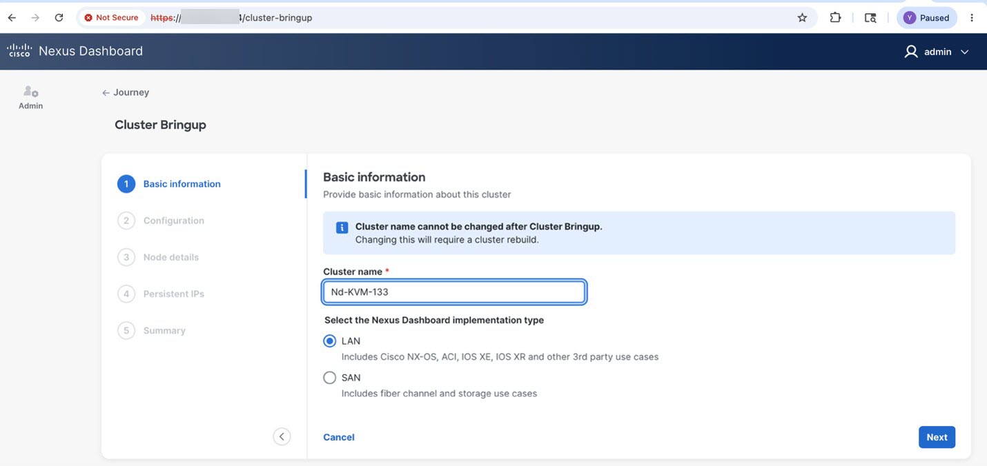
Enter the requested information in the Basic Information page of the Cluster Bringup wizard.
For Cluster Name, enter a name for this Nexus Dashboard cluster.
The cluster name must follow the RFC-1123 requirements.
For Select the Nexus Dashboard Implementation type, choose either LAN or SAN then click Next.
Step 15
Enter the requested information in the Configuration page of the Cluster Bringup wizard.
(Optional) If you want to enable IPv6 functionality for the cluster, put a check in the Enable IPv6 checkbox.
Click +Add DNS provider to add one or more DNS servers, enter the DNS provider IP address, then click the checkmark icon.
(Optional) Click +Add DNS search domain to add a search domain, enter the DNS search domain IP address, then click the checkmark icon.
(Optional) If you want to enable NTP server authentication, put a check in the NTP Authentication checkbox.
If you enabled NTP authentication, click + Add Key, enter the required information, and click the checkmark icon to save the information.
Key–Enter the NTP authentication key, which is a cryptographic key that is used to authenticate the NTP traffic between the Nexus
Dashboard and the NTP servers. You will define the NTP servers in the following step, and multiple NTP servers can use the
same NTP authentication key.
ID–Enter a key ID for the NTP host. Each NTP key must be assigned a unique key ID, which is used to identify the appropriate
key to use when verifying the NTP packet.
Authentication Type–Choose authentication type for the NTP key.
Put a check in the Trusted checkbox if you want this key to be trusted. Untrusted keys cannot be used for NTP authentication.
If you want to enter additional NTP keys, click + Add Key again and enter the information.
If you enabled NTP authentication, click +Add NTP Host Name/IP Address, enter the required information, and click the checkmark icon to save the information.
NTP Host–Enter an IP address; fully qualified domain names (FQDN) are not supported.
Key ID–Enter the key ID of the NTP key you defined in the previous substep.
If NTP authentication is disabled, this field is grayed out.
Put a check in the Preferred checkbox if you want this host to be preferred.
Note
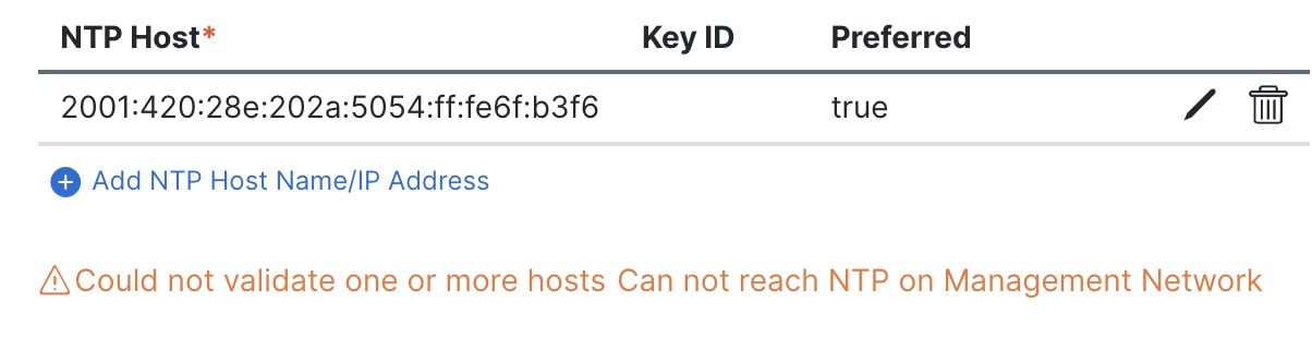
If the node into which you are logged in is configured with only an IPv4 address, but you have checked Enable IPv6 in a previous step and entered an IPv6 address for an NTP server, you will get the following validation error:
This is because the node does not have an IPv6 address yet and is unable to connect to an IPv6 address of the NTP server.
You will enter IPv6 address in the next step. In this case, enter the other required information as described in the following
steps and click Next to proceed to the next page where you will enter IPv6 addresses for the nodes.
If you want to enter additional NTP servers, click +Add NTP Host Name/IP Address again and enter the information.
For Proxy Server, enter the URL or IP address of a proxy server.
For clusters that do not have direct connectivity to Cisco cloud, we recommend configuring a proxy server to establish the
connectivity. This allows you to mitigate risk from exposure to non-conformant hardware and software in your fabrics.
You can click +Add Ignore Host to enter one or more destination IP addresses for which traffic will skip using the proxy.
If you do not want to configure a proxy, click Skip Proxy then click Confirm.
(Optional) If your proxy server requires authentication, put a check in the Authentication required for Proxy checkbox and enter the login credentials.
(Optional) Expand the Advanced Settings category and change the settings if required.
Under advanced settings, you can configure these settings:
App Network–The address space used by the application's services running in the Nexus Dashboard. Enter the IP address and netmask.
Service Network–An internal network used by Nexus Dashboard and its processes. Enter the IP address and netmask.
App Network IPv6–If you put a check in the Enable IPv6 checkbox earlier, enter the IPv6 subnet for the app network.
Service Network IPv6–If you put a check in the Enable IPv6 checkbox earlier, enter the IPv6 subnet for the service network.
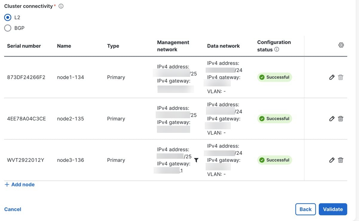
In the Node Details page, update the first node's information.
You have defined the Management network and IP address for the node into which you are currently logged in during the initial
node configuration in earlier steps, but you must also enter the Data network information for the node before you can proceed
with adding the other primary nodes and creating the cluster.
For Cluster Connectivity, if your cluster is deployed in L3 mode, choose BGP. Otherwise, choose L2.
You can enable BGP at this time or in the Nexus Dashboard GUI after the cluster is deployed. All remaining nodes need to configure
BGP if it is configured. You must enable BGP now if the data network of nodes have different subnets.
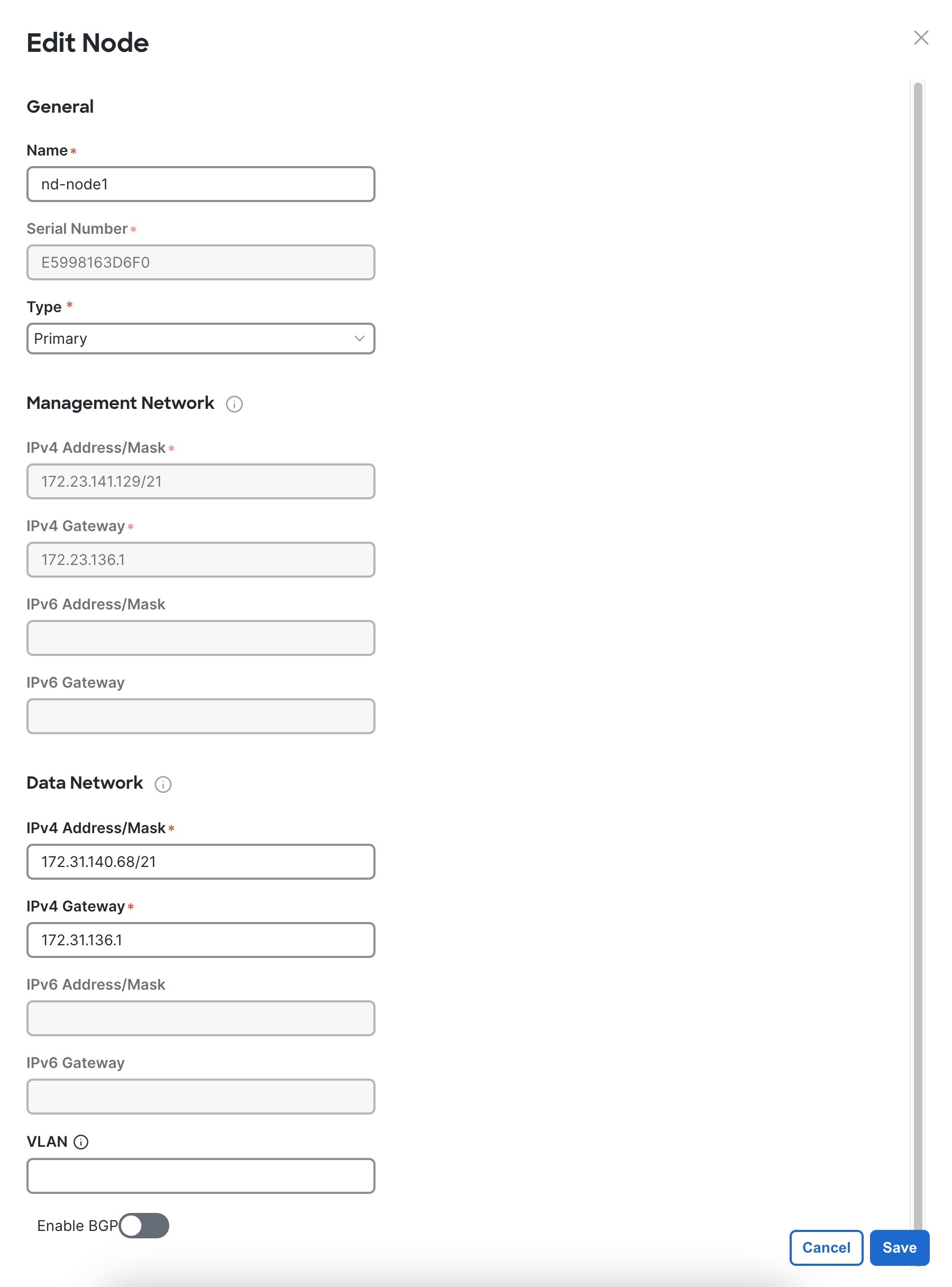
Click the Edit button next to the first node.
The node's Serial Number, Management Network information, and Type are automatically populated, but you must enter the other information.
For Name, enter a name for the node.
The node's Name will be set as its hostname, so it must follow the RFC-1123 requirements.
Note
If you need to change the name but the Name field is not editable, run the CIMC validation again to fix this issue.
For Type, choose Primary.
The first nodes of the cluster must be set to Primary. You will add the secondary nodes in a later step if required for higher scale.
In the Data Network area, enter the node's data network information.
Enter the data network IP address, netmask, and gateway. Optionally, you can also enter the VLAN ID for the network. Leave
the VLAN ID field blank if your configuration does not require VLAN. If you chose BGP for Cluster Connectivity, enter the ASN.
If you enabled IPv6 functionality in a previous page, you must also enter the IPv6 address, netmask, and gateway.
Note
If you want to enter IPv6 information, you must do so during the cluster bootstrap process. To change the IP address configuration
later, you would need to redeploy the cluster.
All nodes in the cluster must be configured with either only IPv4, only IPv6, or dual stack IPv4/IPv6.
If you chose BGP for Cluster Connectivity, then in the BGP peer details area, enter the peer's IPv4 address and ASN.
You can click + Add IPv4 BGP peer to add addition peers.
If you enabled IPv6 functionality in a previous page, you must also enter the peer's IPv6 address and ASN.
Click Save to save the changes.
Step 17
In the Node Details screen, click Add Node to add the second node to the cluster.
If you are deploying a single-node cluster, skip this step.
In the Deployment Details area, provide the Management IP Address and Password for the second node
You defined the management network information and the password during the initial node configuration steps.
Click Validate to verify connectivity to the node.
The node's Serial Number and the Management Network information are automatically populated after connectivity is validated.
Provide the Name for the node.
From the Type dropdown, select Primary.
The first 3 nodes of the cluster must be set to Primary. You will add the secondary nodes in a later step if required for higher scale.
In the Data Network area, provide the node's Data Network information.
You must provide the data network IP address, netmask, and gateway. Optionally, you can also provide the VLAN ID for the network.
For most deployments, you can leave the VLAN ID field blank.
If you had enabled IPv6 functionality in a previous screen, you must also provide the IPv6 address, netmask, and gateway.
Note
If you want to provide IPv6 information, you must do it during cluster bootstrap process. To change IP configuration later,
you would need to redeploy the cluster.
All nodes in the cluster must be configured with either only IPv4, only IPv6, or dual stack IPv4/IPv6.
(Optional) If your cluster is deployed in L3 mode, Enable BGP for the data network.
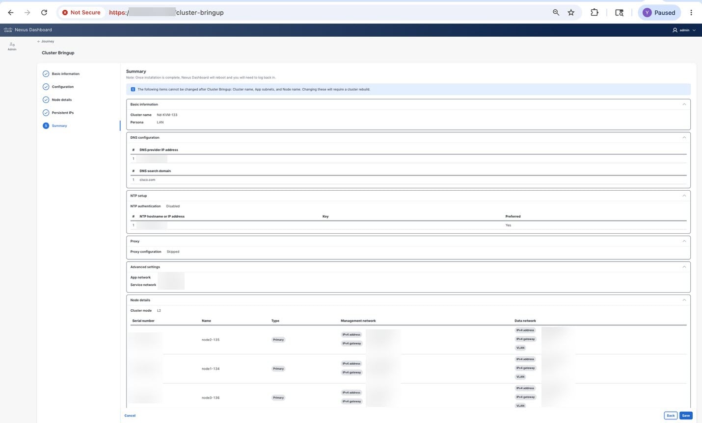
In the Summary screen, review and verify the configuration information and click Save to build the cluster.
During the node bootstrap and cluster bring-up, the overall progress as well as each node's individual progress will be displayed
in the UI. If you do not see the bootstrap progress advance, manually refresh the page in your browser to update the status.
It may take up to 30 minutes for the cluster to form and all the services to start. When cluster configuration is complete,
the page will reload to the Nexus Dashboard GUI.
Step 21
Verify that the cluster is healthy.
After the cluster becomes available, you can access it by browsing to any one of your nodes' management IP addresses. The
default password for the admin user is the same as the rescue-user password you chose for the first node. During this time, the UI will display a banner at the top stating "Service Installation
is in progress, Nexus Dashboard configuration tasks are currently disabled".
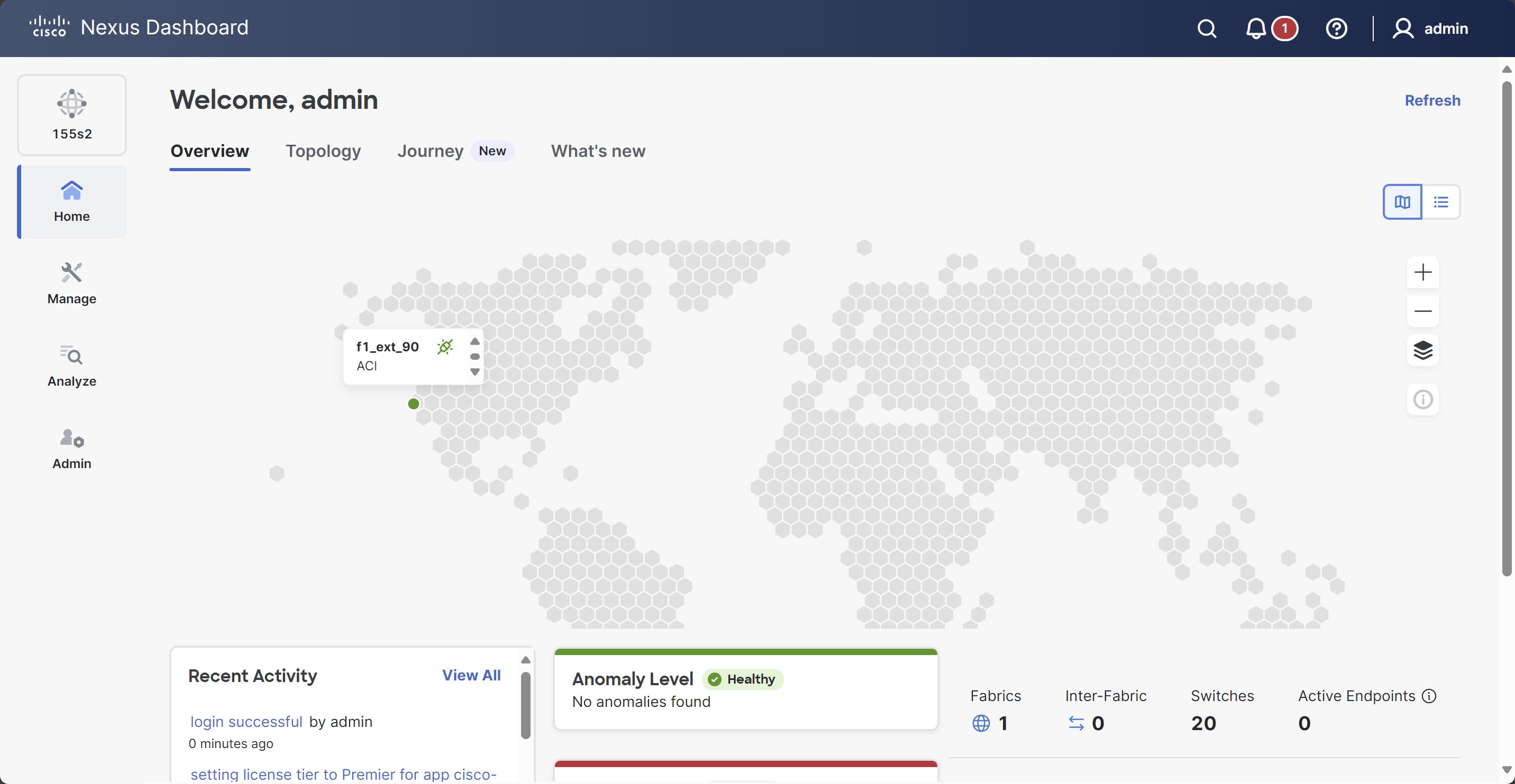
After all the cluster is deployed and all services are started, you can look at the Anomaly Level on the Home > Overview page to ensure the cluster is healthy:
Alternatively, you can log in to any one node using SSH as the rescue-user using the password you entered during node deployment and using the acs health command to see the status:
While the cluster is converging, you may see the following output:
$ acs healthk8s install is in-progress
$ acs healthk8s services not in desired state - [...]
$ acs healthk8s: Etcd cluster is not ready
When the cluster is up and running, the following output will be displayed:
$ acs health
All components are healthy
Note
In some situations, you might power cycle a node (power it off and then back on) and find it stuck in this stage:
deploy base system services
This is due to an issue with etcd on the node after a reboot of the physical Nexus Dashboard cluster.
To resolve the issue, enter the acs reboot clean command on the affected node.
Step 22
(Optional) Connect your Cisco Nexus Dashboard cluster to Cisco Intersight for added visibility and benefits. Refer to Working with Cisco Intersight for detailed steps.
Step 23
After you have deployed Nexus Dashboard, see the collections page for this release for configuration information.
What to do next
The next task is to create the fabrics and fabric groups. See the Creating Fabrics and Fabric Groups article for this release on the Cisco Nexus Dashboard collections page.

 Feedback