Configuring HBA Link Diagnostics

Overview

The HBA Link Diagnostics feature helps in validating the health of links between Host Bus Adapters (HBAs) and Cisco MDS switches in a network.

Servers connect to Storage Area Networks (SANs) through hardware devices called HBAs. This connectivity comprises of many optical and electrical components that may develop faults during their lifetime. This feature allows identification of faulty cables, transceivers, ASICs, drivers, firmware issues or software issues, thereby eliminating dropped frames and ensuring reliable I/O operations of the server.

Supported Platforms

HBA Link Diagnostics is supported on the following platforms:

  • Cisco MDS 48-Port 16-Gbps Fibre Channel Switching Module: DS-X9448-768K9

  • Cisco MDS 48-Port 32-Gbps Fibre Channel Switching Module: DS-X9648-1536K9

  • Cisco MDS 24/10 SAN Extension Module (FC ports only): DS-X9334-K9

  • Cisco MDS 9132T Multilayer Fabric Switch

  • Cisco MDS 9148T Multilayer Fabric Switch

  • Cisco MDS 9396S Multilayer Fabric Switch

  • Cisco MDS 9396T Multilayer Fabric Switch

Guidelines and Limitations

  • From Cisco MDS NX-OS Release 8.3(1), the HBA Link Diagnostics feature is supported in N port virtualization (NPV) mode and switch mode. This feature is supported on the following platforms:

    • Cisco MDS 9132T Multilayer Fabric Switch

    • Cisco MDS 9148T Multilayer Fabric Switch

    • Cisco MDS 9396T Multilayer Fabric Switch

    • Cisco MDS 9396S Multilayer Fabric Switch

  • In Cisco MDS NX-OS Release 8.2(1), the HBA Link Diagnostics feature is supported only in switch mode on the Cisco MDS 9396S Multilayer Fabric Switch, the HBA Link Diagnostics feature in N port virtualization (NPV) mode is not supported.

  • HBA links can be established in F port mode or Auto mode however, HBA link diagnostics tests can be run on interfaces in F port mode only.

  • When link diagnostics tests are running, the generator and host bus adapter (HBA) ports cannot be used for regular Fibre Channel (FC) traffic or for other tests, such as, Inter Switch Link (ISL) diagnostics.

  • There must be at least one free or unused port in the switch available to be used as the traffic generator port. This port needs to be in admin shutdown status during the HBA link diagnostic tests.

  • When a chassis reloads, switch over, or a module hosting the generator or diagnostic ports reloads, the diagnostic tests will be terminated.

  • When more than one loopback test fails, only the lowest level failure is reported. We recommend that you first fix the reported failure, and then rerun the tests.

  • The port LEDs on the diagnostic port are solid green color even when traffic tests are running.

  • The maximum line rate of the diagnostic port that can be tested depends on the generator port's capability and the user specified line rate. For example, if the diagnostic port is running on a 32 Gbps switching module and the generator port is running on a 16 Gbps switching module, and the rate of traffic generation is set to 50%, then the maximum line rate that is supported by the diagnostic port is 8 Gbps.

  • HBA link diagnostics tests are not supported on FEC-enabled links at 16 Gbps.

HBA Link Diagnostics Tests

HBA link diagnostics is a useful tool to validate the performance and isolate faulty remote-peer and HBA components. Different types of tests are available to verify the operation of different components in the path to, and the stack of, the target device.

Link diagnostics tests are configured and controlled from the MDS switch. The target HBA and SFP must support the intended types of tests. The link is set to a diagnostic mode which removes it from the SAN fabric. The test traffic can then be run exclusively on the specific link without interfering with the fabric traffic. When the tests are complete, the link can be taken out of the diagnostic mode and returned to service in the SAN fabric.

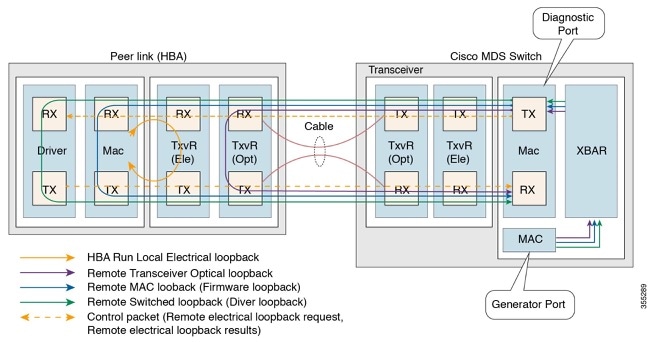
Two ports, a diagnostic port and a generator port, are required to run the tests. The diagnostic port is the port on which the tests are run. The generator port generates traffic required to run the tests. If the generator port is not explicitly specified by the user while starting the diagnostics tests, then any port that is in admin shutdown status is selected as the generator port.

The following are the different types of link diagnostics tests available on Cisco MDS switches:

  • Latency Test

  • Loopback Traffic Tests

Both the link diagnostics tests can be run at different supported levels. For more information, see the Levels of HBA Link Diagnostics Tests section.

Latency Test

The Latency test measures the round-trip latency of the link between the HBA and the Cisco MDS switch.

The test frame is looped back by the HBA port to the generator switch port where timestamps are captured. Timestamps allow the latency of the link to be measured in both directions as well as the latency of the HBA port.

The latency test with optical loopback helps in determining the cable length. The cable length calculations are not applicable to any other latency tests. The accuracy of the reported cable length is within +/- 5 meters.

Loopback Traffic Tests

A loopback test sends and receives data from a single port to verify if that port is operational. The loopback traffic tests can be run at different levels. For more information, see the Levels of HBA Link Diagnostics Tests section.

Levels of HBA Link Diagnostics Tests

The HBA Link Diagnostics feature supports the following levels at which link diagnostics tests can be performed:

  • Remote Switched

  • MAC

  • Electrical

  • Optical

The following figure denotes the different levels of HBA link diagnostics tests:

Figure 1. Levels of HBA Link Diagnostics Tests

Remote Switched

Frames are looped back by the peer device at the highest layer that is supported by diagnostics in the stack (FC-2 or above). This functionality is implemented in the FC driver on the peer server CPU.


Note


Only 100 frames will be transferred in the following scenarios:

  • User input of duration as x seconds

  • User input of frame-count greater than 100 frames

The requested number of frames is sent when the frame count is less than 100 frames.


MAC

Frames are looped back by the peer device at the MAC (FC-1) layer of the peer HBA. This functionality is implemented in the firmware code on the HBA.

Electrical

Frames are looped back by the peer device at the electrical stage of the transceiver (FC-0) of the peer HBA. This functionality is implemented by the peer HBA firmware programming the local transceiver for electrical loopback.


Note


The electrical loopback level does not support Latency test.


Optical

A frame loopback is done in the optical part of the transceiver (FC-0) at the HBA side. The optical loopback is achieved by programming the transceiver from the firmware layer of the HBA.

Configuring HBA Link Diagnostics

To run HBA link diagnostic tests, first set the port connected to the HBA into diagnostic mode and then run the tests from this port.

When link testing is finished, move the port connected to the HBA back to service.

Configuring Link Diagnostic Mode on a Port

To configure link diagnostic mode on a port, perform the following tasks:

Before you begin

  • Ensure that supported SFPs are used on the HBA.

  • Install supported versions of the driver or firmware on the HBA and configure the diagnostic parameters.

Procedure


Step 1

Enter global configuration mode:

switch# configure terminal

Step 2

Specify the interface to be used as the diagnostic port and enter interface configuration mode:

switch(config)# interface fc slot/port

Step 3

Gracefully shut down the interface and administratively disable the traffic flow

switch(config-if)# shutdown

Note


Configurations done through ASCII files will not enter link diagnostic mode if the interface is not in admin shut state.

Step 4

Configure the link diagnostic mode on the specified port:

switch(config-if)# switchport link-diag

Note


To unconfigure the link diagnostic mode on the specified port, use the no switchport link-diag command.

Step 5

Enable the interface:

switch(config-if)# no shutdown

Step 6

Exit the interface:

switch(config-if)# end


Example


Note


  • The diagnostic port will be in initializing state when it is configured using the configurations listed in "Configuring Link Diagnostic Mode on a Port" section.

  • Unconfigure and reconfigure the link diagnostic mode on the switch whenever there is a change in the HBA such as driver load, unload, HBA port reset, and so on.


The following running configuration shows how to enable link diagnostic mode on an interface. Replace the placeholders with relevant values for your setup.


configure terminal
 interface fc <1/1>
 	shutdown
 	switchport link-diag
 	no shutdown
	 end

Running Link Diagnostic Tests on a Port

To run link diagnostic tests on a port, perform the following task:

Procedure


Run link diagnostic tests on a specified port:

switch# diagnostic start interface fc slot/port test link-diag [ duration seconds | frame-count count ] [ frame-size min min_bytes max max_bytes step step_size ] [ gen-interface fc slot/port ] [ level { remote levels |remote-all} ] [ payload { random | fixed fixed_payload } ] [ rate line_rate]

Note

 
  • By default, tests are run at all supported levels if it is not explicitly selected using the level remote levels option.

  • The generator port is autoselected if it is not explicitly configured using the gen-interface fc slot/port option. For more information about this command, see the Cisco MDS 9000 Series Command Reference.

  • User specified frame-count count may not match the actual number of transmitted frames due to in-switch drops.

  • Avoid clearing counters or statistics on interfaces where link diagnostic tests are running.

  • On interfaces where link diagnostic tests are running, new configurations that are attempted will be successful only after the completion of the link diagnostic tests.


Running Link Diagnostic Tests on a Port

This example shows how to run link diagnostic tests on a diagnostic port. In the following example, link diagnostic mode is configured on fc1/1 interface.

switch# diagnostic start interface fc1/1 test link-diag

The following command outputs display the result of the tests that are running on a diagnostic port:

switch# show diagnostic result interface fc1/1 test link-diag
PWWN of peer port: 21:00:00:24:ff:17:09:ac
Status: Supported (Reflector)
Reflector loopback capabilities:  Xcvr-optical Electrical
Time of Test: Thu Sep 14 00:20:11 2017
Total time taken: 30 seconds
===================|=================|=================|===========================|==================|=================
                   |                 |                 |     Discards              |    Latency (ns)  |
Loopback Level     |    Tx Frames    |    Rx Frames    |  IN    |  OUT   |BAD WORDS|In-Switch|External|    Status
===================|=================|=================|========|========|=========|=========|========|=================
Remote-Switched(R) |                0|                0|       0|       0|        0|        0|       0|       -NA-
Mac(R)             |                0|                0|       0|       0|        0|        0|       0|       -NA-
Xcvr-optical(R)    |          1000000|          1000000|       0|       0|        0|     2136|     632|    Success
Electrical(R)      |            20000|            20000|            -NA-           |     -NA-|    -NA-|    Success
========================================================================================================================
 
Overall Status                          : Success
Cable Length (approx. +/- 5 metres)     : 38.2 metres

Note


The annotation (R) denotes the remote-peer or HBA port.


The following command output displays the link diagnostics capabilities of the peer device:

switch# show diagnostic result interface fc1/1 test link-diag peer-capability
pWWN of Peer Port: 10:23:34:90:fa:cd:16:6c
Status: Supported (Reflector)
Reflector Loopback Capabilities:   Remote-switched MAC Xcvr-optical


The following running configuration shows how to unconfigure the link diagnostic mode on an interface. Replace the placeholders with relevant values for your setup.


configure terminal
 interface fc <1/1>
 	shutdown
 	no switchport link-diag
 	no shutdown
	 end

Terminating Link Diagnostic Tests on a Port

To terminate link diagnostic tests on a port, perform the following task:

Procedure


Terminate link diagnostic tests on a specified port:

switch# diagnostic stop interface fc slot/port test link-diag


Example: Terminating Link Diagnostic Tests on a Port

The following example shows how to terminate link diagnostic tests on a port. In the following example, link diagnostic mode is configured on fc1/1 interface.

switch# diagnostic stop interface fc 1/1 test link-diag

The following command output displays the result of the terminated tests on a diagnostic port:

switch# show diagnostic result interface fc 1/1 test link-diag
PWWN of peer port: 10:00:00:90:fa:c7:e1:e9
Status: Supported (Reflector)
Reflector loopback capabilities:  Remote-switched MAC Xcvr-optical
Time of Test: Wed Sep 20 12:54:59 2017
Total time taken: 10 seconds
===================|=================|=================|===========================|==================|=================
                   |                 |                 |     Discards              |    Latency (ns)  |
Loopback Level     |    Tx Frames    |    Rx Frames    |  IN    |  OUT   |BAD WORDS|In-Switch|External|    Status
===================|=================|=================|========|========|=========|=========|========|=================
Remote-Switched(R) |                0|                0|       0|       0|        0|        0|       0|       -NA-
Mac(R)             |                0|                0|       0|       0|        0|        0|       0|       -NA-
Xcvr-optical(R)    |              439|              439|            -NA-           |        0|       0|    Stopped
Electrical(R)      |                0|                0|       0|       0|        0|        0|       0|       -NA-
========================================================================================================================

Overall Status                          : User Stop/Module Reload/PortDown/ELS error
                                          [DIAG TEST STOPPED]
Cable Length (approx. +/- 5 metres)     : -NA-

Note


The annotation (R) denotes the remote-peer or HBA port.


Troubleshooting HBA Link Diagnostics

The following commands can be used to troubleshoot common HBA link diagnostics issues:

  • To check if link diagnostics is enabled on an interface, use the show interface fc slot/port command.
    switch# show interface fc1/1
    fc1/1 is down (Initializing)
    Hardware is Fibre Channel, SFP is short wave laser w/o OFC (SN)
        Port WWN is 20:25:40:55:39:0c:70:80
        Admin port mode is auto, trunk mode is on
        snmp link state traps are enabled
        Port vsan is 1
        Receive data field Size is 2112
        Beacon is turned off
        Logical type is edge
        Link Diagnostics enabled
        5 minutes input rate 0 bits/sec,0 bytes/sec, 0 frames/sec
        5 minutes output rate 0 bits/sec,0 bytes/sec, 0 frames/sec
          26654656 frames input,53267399028 bytes
            0 discards,0 errors
            0 invalid CRC/FCS,0 unknown class
            0 too long,0 too short
          26654687 frames output,53267399756 bytes
            0 discards,0 errors
          31 input OLS,31  LRR,33 NOS,0 loop inits
          61 output OLS,0 LRR, 27 NOS, 0 loop inits
        Last clearing of "show interface" counters :  never
  • To check if an interface is being used as the generator port, use the show interface fc slot/port command.
    switch# show interface fc 1/1
    fc1/2 is down (Administratively down)
        Hardware is Fibre Channel, SFP is short wave laser w/o OFC (SN)
        Port WWN is 20:02:8c:60:4f:0d:20:80
        Admin port mode is auto, trunk mode is on
        snmp link state traps are enabled
        Port vsan is 1
        Receive data field Size is 2112
        Beacon is turned off
        Logical type is Unknown(0)
        Link Diagnostics generator port
        5 minutes input rate 0 bits/sec,0 bytes/sec, 0 frames/sec
        5 minutes output rate 0 bits/sec,0 bytes/sec, 0 frames/sec
          0 frames input,0 bytes
            0 discards,0 errors
            0 invalid CRC/FCS,0 unknown class
            0 too long,0 too short
          0 frames output,0 bytes
            0 discards,0 errors
          0 input OLS,0  LRR,0 NOS,0 loop inits
          0 output OLS,0 LRR, 0 NOS, 0 loop inits
        Last clearing of "show interface" counters :  never
    
  • To check the link diagnostics tests that are running on the switch, use the show diagnostic test link-diag status command.
    switch# show diagnostic test link-diag status
    ---------------------------------------------------------------------------------------------------------------------
    Index  Diag-Interface    Gen-Interface    Link-diag Status
    ----------------------------------------------------------------------------------------------------------------------
                                              Remote-Switched(R)      MAC(R)          Electrical(R)    Xcvr-optical(R)
    ----------------------------------------------------------------------------------------------------------------------
    1       fc2/9             fc2/1             NA                   Running                 NA                 NA
  • To collect information for Cisco technical support for this feature, use the show tech-support link-diag command.