
Prepare a failed switch for Return Merchandise Authorization (RMA)
Preparing a failed switch for RMA and installing the replacement
A failed switch Return Merchandise Authorization (RMA) is a replacement workflow that removes a failed switch from an existing Cisco Nexus Hyperfabric fabric and returns a like-for-like replacement switch to the same logical node.
This workflow differs from initial onboarding because the goal is not to add a new logical node in the fabric blueprint. The goal is to restore an existing node in the fabric by replacing the failed physical switch. The physical switch changes, but the intended node functionality in the fabric stays the same.
How the RMA workflow works
Summary
The workflow starts with a failed switch that is already claimed and bound to a node in the fabric blueprint before the replacement starts. The workflow ends when the replacement switch is bound to the node and operating as expected.
Workflow
These are the stages of the RMA workflow.
- Confirm RMA as directed from Cisco Technical Assistance Center (TAC), and verify that your physical switch requires replacement.
- Unbind the failed switch from the node in the fabric blueprint, commit the change, and unclaim the failed switch from inventory.
- Install and onboard the replacement switch, claim it, and bind it to the logical node that is in an unbound state. When the replacement switch is bound to the node and committed, the previous node configuration from the blueprint will be automatically applied. Other than the serial number of the physical device, the intended node-level configuration remains the same.
Prepare the failed switch for RMA process
Complete this task to remove the failed switch from the logical node in the fabric blueprint and make that node available for the replacement switch. This task covers the cleanup actions for the failed switch only.
Use this task only when Cisco Technical Assistance Center (TAC) has instructed you to perform the RMA process for a failed switch that is already claimed and bound to the fabric.
Before you start:
- Confirm that no active traffic is passing through the failed switch.
- Identify the failed switch by noting its hostname, serial number, and node location.
- Ensure that you have permission to modify the fabric and unclaim devices.
Step 1 | Select Fabrics, then select the fabric that contains the failed switch. |
Step 2 | If the fabric is not in the edit mode, select Switch to edit mode. |
Step 3 | In the Topology area, select the failed switch in the fabric and verify that you are removing the correct switch. Compare the displayed device details with the known information for the failed switch, such as the hostname, serial number, or node location. |
Step 4 | Select Unbind to unbind the failed switch from its logical position in the fabric. Unbinding the switch removes the device assignment from the logical node so that the node becomes available for the replacement switch. |
Step 5 | Commit the fabric change.
|
Step 6 | Unclaim the failed switch in the inventory.
|
The failed switch is no longer bound to the fabric node and is no longer claimed in inventory. The logical node is ready for the replacement switch.
Install and onboard the replacement switch
This procedure covers the high-level tasks to bring the replacement switch online and prepare it for claiming. Use the normal onboarding flow for the replacement switch so that it can connect to the Cisco Nexus Hyperfabric cloud service. For more information, refer to Getting Started.
The replacement switch should be a supported like-for-like replacement for the failed switch.
Step 1 | Physically install the replacement switch.
|
Step 2 | Power on the replacement switch. |
Step 3 | Complete the craft console procedure for switch onboarding. |
Step 4 | Verify that the replacement switch connects to the Cisco Nexus Hyperfabric cloud service. |
Step 5 | Allow the replacement switch to complete any required switch software version and agent updates. When you connect the replacement switch to the Cisco Nexus Hyperfabric cloud service, the switch software and the agent will be automatically upgraded to the latest version. During this process, the switch might reboot. Expect this reboot and do not turn off or unplug the switch while it is updating to make sure everything works correctly. |
The replacement switch is reachable, connected to the cloud service, and ready to be claimed.
Claim the replacement switch
Complete this task so that Cisco Nexus Hyperfabric recognizes the replacement switch as a claimed device that is ready to bind to the logical node.
The replacement switch must already be connected to the cloud before you begin the claim process.
Step 1 | If using a claim code, log in to the switch and get the claim code that is shown in the serial console menu. The claim code that displays in the console changes every two minutes, although a code is valid for four minutes. Use the claim code that matches the replacement hardware. 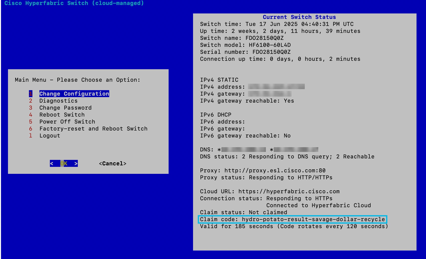
|
Step 2 | In the Nexus Hyperfabric GUI, choose Inventory |
Step 3 | Select Claim devices |
Step 4 | If you have a claim code:
|
Step 5 | If you are not using a claim code:
Cisco Nexus Hyperfabric recognizes the replacement switch as a claimed device that is ready to bind to the logical node. |
The replacement switch is claimed in inventory. You can now bind the replacement switch to the fabric blueprint.
Bind the replacement switch to the fabric blueprint
Complete this task to restore the logical node in the fabric by attaching the claimed replacement switch to it. This task is where the logical node configuration is restored to the replacement switch.
Step 1 | Select Fabrics, then select the fabric that contains the logical node as the target for the replacement switch. |
Step 2 | If the fabric is not in the edit mode, select Switch to edit mode. |
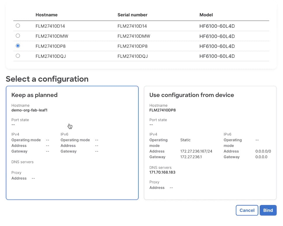
Step 3 | Bind the replacement switch.
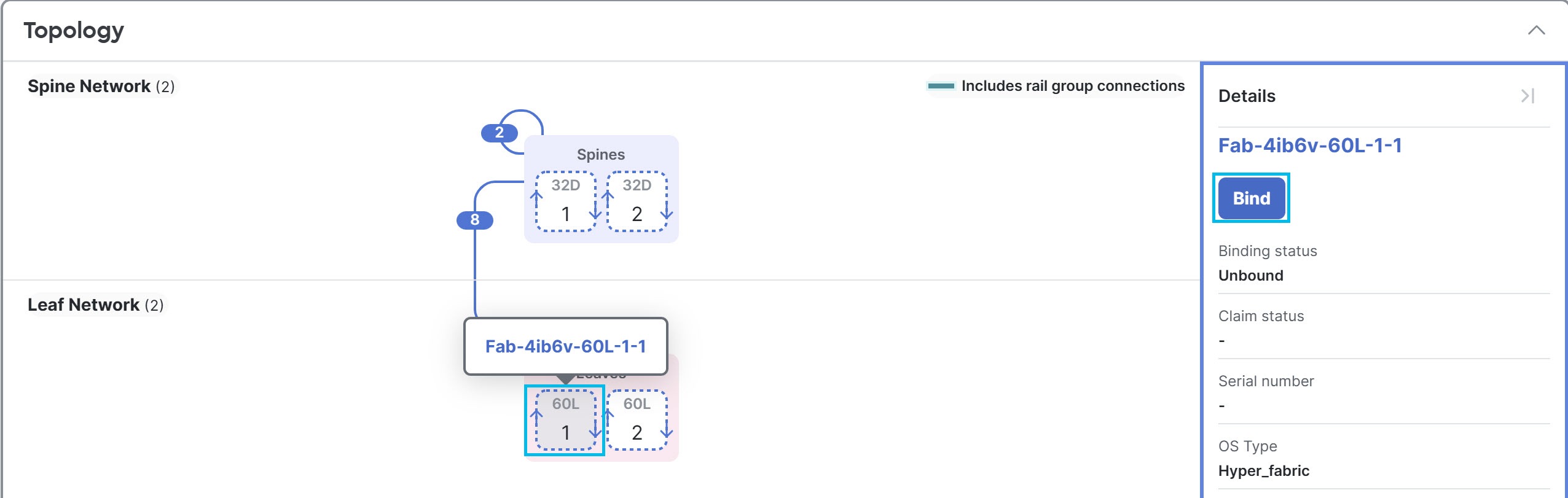
|
Step 4 | Commit the fabric change.
|
The replacement switch is bound to the logical node and gets its node configuration from the fabric blueprint. If the switch software version in the fabric blueprint is different from the version the replacement switch was last updated to when connected to the Cisco Nexus Hyperfabric cloud service (refer to the last step in Install and onboard the replacement switch), the switch will change to the version defined in the blueprint. This causes the switch to reboot. During this update, do not turn off or unplug the switch to ensure it works properly. For more information, refer to Software Lifecycle Management.