Multi-Pod

This chapter contains the following sections:

About Multi-Pod

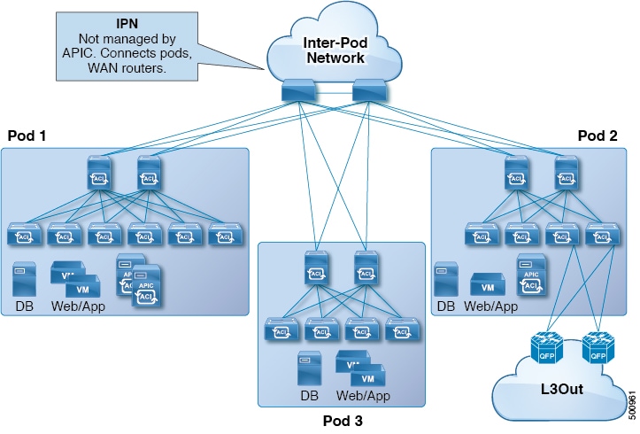
Multi-Pod enables provisioning a more fault-tolerant fabric comprised of multiple pods with isolated control plane protocols. Also, Multi-Pod provides more flexibility with regard to the full mesh cabling between leaf and spine switches. For example, if leaf switches are spread across different floors or different buildings, Multi-Pod enables provisioning multiple pods per floor or building and providing connectivity between pods through spine switches.

Multi-Pod uses MP-BGP EVPN as the control-plane communication protocol between the ACI spines in different pods.

In releases before Cisco APIC Release 5.2(3), OSPF is used in the underlay to peer between the physical spines and the IPN. Beginning with Cisco APIC Release 5.2(3), the underlay protocol can be OSPF or BGP (eBGP only) or a mixture, with some pods using OSPF and some using BGP.

WAN routers can be provisioned in the Inter-Pod Network (IPN), directly connected to spine switches, or connected to border leaf switches. Spine switches connected to the IPN are connected to at least one leaf switch in the pod.

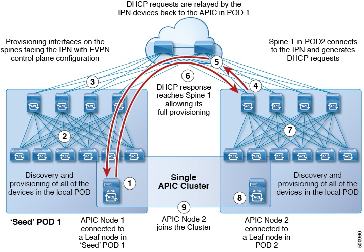
Multi-Pod uses a single APIC cluster for all the pods; all the pods act as a single fabric. Individual APIC controllers are placed across the pods but they are all part of a single APIC cluster.

Figure 1. Multi-Pod Overview

Note


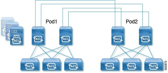
Beginning with Cisco APIC Release 5.2(3), a fabric consisting of only two pods can be connected directly, without an IPN. For information about this Multi-Pod Spines Back-to-Back topology, see About Multi-Pod Spines Back-to-Back.

Multi-Pod Provisioning

The IPN is not managed by the APIC. It must be preconfigured with the following information:

  • Configure the interfaces connected to the spines of all pods. Use Layer 3 sub-interfaces tagging traffic with VLAN-4 and increase the MTU at least 50 bytes above the maximum MTU required for inter-site control plane and data plane traffic.

    If remote leaf switches are included in any pods, see Remote Leaf Switches and the Cisco ACI Remote Leaf Architecture White Paper.

  • If the IPN underlay protocol will be OSPF, enable OSPF on sub-interfaces with the correct area ID. Beginning with Cisco APIC Release 5.2(3), the IPN underlay protocol can be either OSPF or BGP (eBGP only).

  • Enable DHCP Relay on IPN interfaces connected to all spines.

  • Enable PIM.

  • Add bridge domain GIPO range as PIM Bidirectional (bidir) group range (default is 225.0.0.0/15).

    A group in bidir mode has only shared tree forwarding capabilities.

  • Add 239.255.255.240/28 as PIM bidir group range.

  • Enable PIM and IGMP on the interfaces connected to all spines.


Note


When deploying PIM bidir, at any given time it is only possible to have a single active RP (Rendezvous Point) for a given multicast group range. RP redundancy is hence achieved by leveraging a Phantom RP configuration. Because multicast source information is no longer available in Bidir, the Anycast or MSDP mechanism used to provide redundancy in sparse-mode is not an option for bidir.
Figure 2. Multi-Pod Provisioning

Guidelines for Setting Up a Cisco ACI Multi-Pod Fabric

To configure a Cisco ACI Multi-Pod fabric, follow these guidelines:

  • Cisco ACI Multi-Pod is supported on the following:

    • All ACI-mode spine switches

    • All Cisco Nexus 9000 Series ACI-mode leaf switches

    • All of the Cisco Nexus 9500 platform ACI-mode switch line cards and fabric modules

  • Create the associated node group and Layer 3 Outside (L3Out) policies.

  • Before you make any changes to a spine switch, ensure that there is at least one operationally “up” external link that is participating in the Cisco ACI Multi-Pod topology. Failure to do so could bring down the Cisco ACI Multi-Pod connectivity.

  • If you have to convert a Cisco ACI Multi-Pod setup to a single pod (containing only Pod 1), the Cisco Application Policy Infrastructure Controllers (APICs) connected to the pods that are decommissioned should be re-initialized and connected to the leaf switches in Pod 1, which will allow them to re-join the cluster after going through the initial setup script. See Moving an APIC from One Pod to Another Pod for those instructions. The TEP pool configuration should not be deleted.

  • Cisco ACI GOLF (also known as Layer 3 EVPN Services for Fabric WAN) and Cisco ACI Multi-Pod can be deployed together over all the switches used in the Cisco ACI Multi-Pod and EVPN topologies.

    For more information on GOLF, see Cisco ACI GOLF.

  • In a Cisco ACI Multi-Pod fabric, the Pod 1 configuration (with the associated TEP pool) must always exist on Cisco APIC, as the Cisco APIC nodes are always addressed from the Pod 1 TEP pool. This remains valid also in the scenario where the Pod 1 is physically decommissioned (which is a fully supported procedure) so that the original Pod 1 TEP pool is not re-assigned to other pods that may be added to the fabric.

  • In a Cisco ACI Multi-Pod fabric setup, if a new spine switch is added to a pod, it must first be connected to at least one leaf switch in the pod. This enables the Cisco APIC to discover the spine switch and join it to the fabric.

  • After a pod is created and nodes are added in the pod, deleting the pod results in stale entries from the pod that are active in the fabric. This occurs because the Cisco APIC uses open source DHCP, which creates some resources that the Cisco APIC cannot delete when a pod is deleted

  • If you connect spine switches belonging to separate pods with direct back-to-back links, an OSPF neighborship might get established on the peer interface between the two spine switches. If there is a mismatch between the peer interfaces, with one of the peers having the Cisco ACI Multi-Pod direct flag disabled, the session won't be up and forwarding will not happen. Even though the system will throw a fault in this situation, this is expected behavior.

  • Beginning with Cisco APIC release 5.2(3), the IPN underlay protocol can be external BGP (eBGP). Internal BGP (iBGP) is not supported as the underlay protocol.

    When preparing to migrate a Cisco ACI Multi-Pod fabric between OSPF and BGP as the IPN underlay, follow these guidelines:

    • A BGP underlay is not supported if the Cisco ACI fabric is connected to a cloud site or to a GOLF router.

    • A BGP underlay supports only an IPv4 address family, not an IPv6 address family.

  • When deploying Cisco APIC cluster connectivity to the fabric over a Layer 3 network, which was introduced in Cisco APIC release 5.2(1), the IPN network can use OSPF as the underlay protocol, or a BGP underlay if the Cisco APIC connects to the fabric using the same network that provides Cisco ACI Multi-Pod or remote leaf switch connectivity.

  • If you delete and recreate the Cisco ACI Multi-Pod L3Out, for example to change the name of a policy, a clean reload of some of the spine switches in the fabric must be performed. The deletion of the Cisco ACI Multi-Pod L3Out causes one or more of the spine switches in the fabric to lose connectivity to the Cisco APICs and these spine switches are unable to download the updated policy from the Cisco APIC. Which spine switches get into such a state depends upon the deployed topology. To recover from this state, a clean reload must be performed on these spine switches. The reload is performed using the setup-clean-config.sh command, followed by the reload command on the spine switch.


Note


Cisco ACI does not support IP fragmentation. Therefore, when you configure Layer 3 Outside (L3Out) connections to external routers, or Multi-Pod connections through an Inter-Pod Network (IPN), it is recommended that the interface MTU is set appropriately on both ends of a link. On some platforms, such as Cisco ACI, Cisco NX-OS, and Cisco IOS, the configurable MTU value does not take into account the Ethernet headers (matching IP MTU, and excluding the 14-18 Ethernet header size), while other platforms, such as IOS-XR, include the Ethernet header in the configured MTU value. A configured value of 9000 results in a max IP packet size of 9000 bytes in Cisco ACI, Cisco NX-OS, and Cisco IOS, but results in a max IP packet size of 8986 bytes for an IOS-XR untagged interface.

For the appropriate MTU values for each platform, see the relevant configuration guides.

We highly recommend that you test the MTU using CLI-based commands. For example, on the Cisco NX-OS CLI, use a command such as ping 1.1.1.1 df-bit packet-size 9000 source-interface ethernet 1/1.


Note


Cisco APIC will always establish a TCP connection to fabric switches with an MTU of 1496 bytes (TCP MSS 1456) regardless of the CP-MTU setting. The IPN network for remote pods and remote leaf switches must support at least 1500 byte MTU for fabric discovery.


  • You can set the global MTU for control plane (CP) packets sent by the nodes (Cisco APIC and the switches) in the fabric at System > System Settings > Control Plane MTU.

  • In a Cisco ACI Multi-Pod topology, the MTU set for the fabric external ports must be greater than or equal to the CP MTU value set. Otherwise, the fabric external ports might drop the CP MTU packets.

  • If you change the IPN or CP MTU, we recommend changing the CP MTU value first, then changing the MTU value on the spine of the remote pod. This reduces the risk of losing connectivity between the pods due to MTU mismatch. This is to ensure that the MTU across all the interfaces of the IPN devices between the pods is large enough for both control plane and VXLAN data plane traffic at any given time. For data traffic, keep in mind the extra 50 bytes due to VXLAN.

  • To decommission a pod, decommission all the nodes in the pod. For instructions, see Decommissioning and Recommissioning a Pod in Cisco APIC Troubleshooting Guide.

Setting Up the Multi-Pod Fabric

In Cisco Application Policy Infrastructure Controller (APIC) 4.0(1) and later, a wizard was added to the GUI to simplify Multi-Pod configuration. To configure Multi-Pod using the GUI, follow the procedures in this section.

Setting up Multi-Pod between two physical pods involves preparing an existing physical pod to communicate over the interpod network (IPN) with the new pod. You then add the physical pod, and Cisco Cisco APIC creates the Multi-Pod fabric.

You can also configure Multi-Pod using the NX-OS style CLI and REST API. See the sections Setting Up Multi-Pod Fabric Using the NX-OS CLI and Setting Up Multi-Pod Fabric Using the REST API in this guide for instructions.

Preparing the Pod for IPN Connectivity

Before you create a new pod, you first must ensure that the existing physical pod can communicate with the new pod.

Procedure


Step 1

Log in to the Cisco APIC.

Step 2

Navigate to Fabric > Inventory.

Step 3

Expand Quick Start and click Add Pod.

Step 4

In the work pane, click Add Pod.

Step 5

In the Configure Interpod Connectivity STEP 1 > Overview panel, review the tasks that are required to configure interpod network (IPN) connectivity, and then click Get Started.

Step 6

In the Configure Interpod Connectivity STEP 2 > IP Connectivity dialog box, complete the following steps:

  1. If you see a Name field in an L3 Outside Configuration area, choose an existing fabric external routing profile from the Name drop-down list.

  2. Using the Spine ID selector, choose the spine.

    Click the + (plus) icon to add the IDs of more spines.

  3. In the Interfaces area, in the Interface field, enter the spine switch interface (slot and port) used to connect to the IPN.

    Click the + (plus) icon to add more interfaces.

  4. In the IPV4 Address field, enter the IPv4 gateway address and network mask for the interface.

  5. From the MTU (bytes) drop-down list, choose a value for the maximum transmit unit of the external network.

    The range is 1500 to 9216.

  6. Click Next.

Step 7

In the Configure Interpod Connectivity STEP 3 > Routing Protocols dialog box, you configure the underlay protocol to peer between the physical spines and the IPN. In releases before Cisco APIC Release 5.2(3), Open Shortest Path First (OSPF) is the only supported underlay. For those earlier releases, or in a later release if you choose OSPF as the Underlay, complete the following substeps in the OSPF area:

  1. Leave the Use Defaults checked or uncheck it.

    When the Use Defaults check box is checked, the GUI conceals the optional fields for configuring OSPF. When it is unchecked, it displays all the fields. The check box is checked by default.

  2. In the Area ID field, enter the OSPF area ID.

  3. In the Area Type area, choose an OSPF area type.

    You can choose NSSA area or Regular area. Stub area is not supported.

  4. (Optional) With the Area Cost selector, choose an appropriate OSPF area cost value. This field appears only when the Use Defaults checkbox is unchecked.

  5. From the Interface Policy drop-down list, choose or configure an OSPF interface policy.

    You can choose an existing policy, or you can create one with the Create OSPF Interface Policy dialog box.

Step 8

Beginning with Cisco APIC Release 5.2(3), the underlay protocol can be either OSPF or BGP. For releases before Cisco APIC Release 5.2(3), or if you chose OSPF as the Underlay in the preceding step, skip this step. If you choose BGP as the Underlay in the Configure Interpod Connectivity STEP 3 > Routing Protocols dialog box, complete the following substeps in the BGP area to configure the BGP underlay:

In the MP-BGP area, leave the Use Defaults check box checked. The GUI conceals the fields for configuring Multiprotocol Border Gateway Protocol (MP-BGP).

  1. Note the nonconfigurable values in the Spine ID, Interface, and IPv4 Address fields.

  2. In the Peer Address field, enter the IP address of the BGP neighbor.

  3. In the Remote AS field, enter the Autonomous System (AS) number of the BGP neighbor.

  4. Click Next.

Step 9

In the Configure Interpod Connectivity STEP 4 > External TEP dialog box, complete the following steps:

  1. Leave the Use Defaults checked or uncheck it.

    When the Use Defaults check box is checked, the GUI conceals the optional fields for configuring the external TEP pool. When it is unchecked, it displays all the fields. The check box is checked by default.

  2. Note the nonconfigurable values in the Pod and Internal TEP Pool fields.

  3. In the External TEP Pool field, enter the external TEP pool for the physical pod.

    The external TEP pool must not overlap the internal TEP pool or external TEP pools belonging to other pods.
  4. In the Data Plane TEP IP field enter the address that is used to route traffic between pods. This address must have a /32 subnet mask.

    You can accept the default address that is generated when you configure the External TEP Pool. Alternatively, you can enter another address, but it must be outside of the external TEP pool.

  5. In the Router ID field, enter the IPN router IP address.

  6. (Optional) In the Loopback Address field, enter the IPN router loopback IP address.

    If you uncheck the Use Defaults, the Cisco APIC displays the nonconfigurable Unicast TEP IP and Spine ID fields.

  7. Click Finish.

    The Summary panel appears, displaying details of the IPN configuration. You can also click View JSON to view the REST API for the configuration. You can save the REST API for later use.

What to do next

Take one of the following actions:

Adding a Pod to Create a Multi-Pod Fabric

The Add Physical Pod dialog enables you to set up a Multi-Pod environment. You define a new physical pod ID and tunnel endpoint (TEP) pool. You also configure the new pod network settings and the subinterfaces for the physical spines.

Before you begin

You have performed the following tasks:

Procedure


Step 1

Log in to Cisco Application Policy Infrastructure Controller (APIC).

Step 2

Take one of the following actions:

  • If you completed the procedure Preparing the Pod for IPN Connectivity and have not closed the Configure Interpod Connectivity dialog box, skip Step 3 through Step 5, and resume this procedure at Step 6.
  • If you have completed the procedure Preparing the Pod for IPN Connectivity and have closed the Configure Interpod Connectivity dialog box, proceed to Step 3 in this procedure.

Step 3

Choose Fabric > Inventory.

Step 4

Click Quick Start and click Add Pod.

Step 5

In the work pane, click Add Pod.

Step 6

In the Add Physical Pod STEP 2 > Pod Fabric dialog box, complete the following steps:

  1. In the Pod ID field, choose the pod ID.

    The pod ID can be any positive integer; however, it must be unique in the Cisco ACI fabric.

  2. In the Pod TEP Pool field, enter the pool address and subnet.

    The pod TEP pool represents a range of traffic encapsulation identifiers and is a shared resource and can be consumed by multiple domains.

  3. With the Spine ID selector, choose the spine ID.

    Choose more spine IDs by clicking the + (plus) icon.

  4. In the Interfaces area, in the Interface field, enter the spine switch interface (slot and port) that is used to connect to the interpod network (IPN).

  5. In the IPv4 Address field, enter the IPv4 gateway address and network mask for the interface.

  6. In the MTU (bytes) field, choose a value for the maximum transmit unit (MTU) of the external network.

    You can configure another interface by clicking the + (plus) icon.

Step 7

In the Add Physical Pod STEP 3 > External TEP dialog box, complete the following steps:

  1. Leave the Use Defaults check box checked or uncheck it to display the optional fields to configure an external TEP pool.

  2. Note the values in the Pod and Internal TEP Pool fields, which are already configured.

  3. In the External TEP Pool field, enter the external TEP pool for the physical pod.

    The external TEP pool must not overlap the internal TEP pool.

  4. In the Dataplane TEP IP field, enter the address that is used to route traffic between pods.

  5. (Optional) In the Unicast TEP IP field, enter the unicast TEP IP address.

    Cisco APIC automatically configures the unicast TEP IP address when you enter the data plane TEP IP address.

  6. (Optional) Note the value in the nonconfigurable Node field.

  7. (Optional) In the Router ID field, enter the IPN router IP address.

    Cisco APIC automatically configures the router IP address when you enter the data plane TEP address.

  8. In the Loopback Address field, enter the router loopback IP address.

    Leave the Loopback Address blank if you use a router IP address.

  9. Click Finish.


Sample IPN Configurations for Multi-Pod For Cisco Nexus 9000 Series Switches

For releases before Cisco APIC Release 5.2(3), the IPN underlay protocol is OSPF. Beginning with Cisco APIC Release 5.2(3), the IPN underlay protocol can be either OSPF or BGP (eBGP only).


Note


  • The deployment of a dedicated VRF in the IPN for Inter-Pod connectivity is optional, but is a best practice recommendation. You can also use a global routing domain as an alternative.

  • For the area of the sample configuration that shows ip dhcp relay address 10.0.0.1, this configuration is valid based on the assumption that the TEP pool of Pod 1 is 10.0.0.0/x.


Sample IPN Configuration with OSPF Underlay Protocol


  (pod1-spine1)-----2/7[ IPN-N9K ]2/9-----(pod2-spine1)
 
 
feature dhcp
feature pim
 
service dhcp
ip dhcp relay
ip pim ssm range 232.0.0.0/8
 
# Create a new VRF for Multipod.
vrf context fabric-mpod
  ip pim rp-address 12.1.1.1 group-list 225.0.0.0/15 bidir
  ip pim rp-address 12.1.1.1 group-list 239.255.255.240/28 bidir
  ip pim ssm range 232.0.0.0/8
 
interface Ethernet2/7
  no switchport
  mtu 9150
  no shutdown
 
interface Ethernet2/7.4
  description pod1-spine1
  mtu 9150
  encapsulation dot1q 4
  vrf member fabric-mpod
  ip address 201.1.2.2/30
  ip router ospf a1 area 0.0.0.0
  ip pim sparse-mode
  ip dhcp relay address 10.0.0.1
  ip dhcp relay address 10.0.0.2
  ip dhcp relay address 10.0.0.3
  no shutdown
 
 
interface Ethernet2/9
  no switchport
  mtu 9150
  no shutdown
 
interface Ethernet2/9.4
  description to pod2-spine1
  mtu 9150
  encapsulation dot1q 4
  vrf member fabric-mpod
  ip address 203.1.2.2/30
  ip router ospf a1 area 0.0.0.0
  ip pim sparse-mode
  ip dhcp relay address 10.0.0.1
  ip dhcp relay address 10.0.0.2
  ip dhcp relay address 10.0.0.3
  no shutdown
 
interface loopback29
  vrf member fabric-mpod
  ip address 12.1.1.1/32
 
router ospf a1
  vrf fabric-mpod
    router-id 29.29.29.29

Sample IPN Configuration with BGP Underlay Protocol

Beginning with Cisco APIC Release 5.2(3), the IPN underlay protocol can be BGP instead of OSPF. The following configuration can be appended to the previous example and the OSPF configuration can be removed.


router bgp 200
  router-id 29.29.29.29
  vrf fabric-mpod
  address-family ipv4 unicast
neighbor 201.1.2.3
  remote-as 65000
  address-family ipv4 unicast
  disable-peer-as-check
neighbor 203.1.2.3
  remote-as 65000
  address-family ipv4 unicast
  disable-peer-as-check

Moving an APIC from One Pod to Another Pod

Use this procedure to move an APIC from one pod to another pod in an Multi-Pod setup.

Procedure


Step 1

Decommission the APIC in the cluster.

  1. On the menu bar, choose System > Controllers.

  2. In the Navigation pane, expand Controllers > apic_controller_name > Cluster as Seen by Node.

  3. In the Navigation pane, click an apic_controller_name that is within the cluster and not the controller that is being decommissioned.

  4. In the Work pane, verify that the Health State in the Active Controllers summary table indicates the cluster is Fully Fit before continuing.

  5. In the Work pane, click Actions > Decommission.

  6. Click Yes.

    The decommissioned controller displays Unregistered in the Operational State column. The controller is then taken out of service and no longer visible in the Work pane.

Step 2

Move the decommissioned APIC to the desired pod.

Step 3

Enter the following commands to reboot the APIC.


apic1# acidiag touch setup
apic1# acidiag reboot

Step 4

In the APIC setup script, specify the pod ID where the APIC node has been moved.

  1. Log in to Cisco Integrated Management Controller (CIMC).

  2. In the pod ID prompt, enter the pod ID.

Note


Do not modify the TEP Pool address information.

Step 5

Recommission the APIC.

  1. From the menu bar, choose SYSTEM > Controllers.

  2. In the Navigation pane, expand Controllers > apic_controller_name > Cluster as Seen by Node.

  3. From the Work pane, verify in the Active Controllers summary table that the cluster Health State is Fully Fit before continuing.

  4. From the Work pane, click the decommissioned controller that displaying Unregistered in the Operational State column.

  5. From the Work pane, click Actions > Commission.

  6. In the Confirmation dialog box, click Yes.

  7. Verify that the commissioned Cisco APIC controller is in the operational state and the health state is Fully Fit.


Migrating from an OSPF IPN Underlay to a BGP IPN Underlay

Beginning with Cisco APIC Release 5.2(3), the IPN underlay protocol can be either OSPF or BGP. To migrate a pod from using an OSPF underlay to a BGP underlay, add a BGP interface to the Logical Interface Profile under the existing IPN-connected L3Out. When that interface is successfully connected to a running BGP peer, you can delete the OSPF Interface Profile.


Note


When both OSPF and BGP are used in the underlay for Multi-Pod, Multi-Site, or Remote Leaf, do not redistribute router-ids into BGP from OSPF on IPN routers. Doing so may cause a routing loop and bring down OSPF and BGP sessions between the spine switch and IPN routers.


Note


Migrating the underlay protocol is a disruptive action and should be done only during a maintenance window.

Procedure


Step 1

From the APIC menu bar, navigate to Tenants > infra > Networking > L3Outs > your IPN L3Out, where your IPN L3Out is the L3Out that connects to the IPN.

Step 2

In the Navigation pane, expand your IPN L3Out and navigate to Logical Node Profiles > your IPN node profile > Logical Interface Profiles > your IPN interface, where your IPN interface is the Logical Interface Profile for the current IPN connection.

The Logical Interface Profile table appears in the work pane.

Step 3

In the work pane, click the Policy tab and the Routed Sub-Interfaces tab below the Policy tab.

Step 4

In the Routed Sub-Interfaces table, double-click the interface of the current IPN connection.

The Routed Sub-Interface dialog box opens.

Step 5

In the Routed Sub-Interface dialog box, perform the following actions:

  1. Click the + icon in the BGP Peer Connectivity Profiles bar to add a BGP peer connection.

    The Create Peer Connectivity Profiles dialog box opens.

  2. In the Peer IPv4 Address field, enter the IP address of the BGP peer.

  3. Configure any other desired settings for the BGP peer connection.

    Note

     
    If you are configuring for migration but not actually migrating at this time, you can set the Admin State to Disabled for now and return to this step when you are ready to migrate. Migration should be done during a maintenance window.
  4. Click Submit to return to the Routed Sub-Interface dialog box.

Step 6

In the Routed Sub-Interface dialog box, click Submit.

Step 7

In the Navigation pane, navigate to Logical Node Profiles > your IPN node profile > Configured Nodes > your IPN node. Follow these steps to verify that the BGP neighbor is UP.

  1. Expand your IPN node and locate the BGP entry, such as BGP for VRF-overlay-1.

  2. Expand the BGP entry and click Neighbors.

  3. In the Neighbors table, find the peer IP address that you configured in Peer IPv4 Address, and verify that the State is "established."

Step 8

In the Navigation pane, under Logical Interface Profiles, right-click the current OSPF Interface Profile and select Delete.

Note

 
Before deleting the OSPF Interface Profile, make sure that the BGP neighbor is UP.

Step 9

In the Navigation pane, navigate to Tenants > infra > Networking > L3Outs > your IPN L3Out.

Step 10

In the work pane, click the Policy tab and the Main tab below the Policy tab.

Step 11

In the work pane, in the Enable BGP/EIGRP/OSPF section, uncheck OSPF, leaving BGP checked.

Step 12

Click Submit.


About Multi-Pod Spines Back-to-Back

Beginning with Cisco APIC Release 5.2(3), the ACI Multi-Pod architecture is enhanced to support connecting the spines of two Pods directly with back-to-back ("B2B") links. With this solution, called Multi-Pod Spines Back-to-Back, the IPN requirement can be removed for small ACI Multi-Pod deployments. Multi-Pod Spines Back-to-Back also brings operational simplification and end-to-end fabric visibility, as there are no external devices to configure.

In the Multi-Pod Spines Back-to-Back topology, the back-to-back spine link interfaces are implemented as L3Outs in the infra tenant. These links are typically carried on direct cable or dark fiber connections between the Pods. Multi-Pod Spines Back-to-Back supports only Open Shortest Path First (OSPF) connectivity between the spine switches belonging to different Pods.

The following figure shows a Multi-Pod Spines Back-to-Back topology with back-to-back spines connected between Pod1 and Pod2.

For detailed information about Multi-Pod Spines Back-to-Back, see the Cisco knowledge base article Cisco ACI Multi-Pod Spines Back-to-Back.

Troubleshooting Multi-Site and Multi-Pod

This section describes how to troubleshoot Multi-Site and Multi-Pod.

Error:400

If you receive the following error:

Error:400 - Invalid Configuration Following Intersite Spines are not configured as Mpod Spines: 1202 

You must enable the fabric external connectivity for all the existing spines and if you are trying to add new spines use the Setup Multipod GUI wizard.

There are two ways to resolve this issue.

  • Enable all the spines under the external routed network:

    • In the APIC GUI, on the menu bar, click Tenant > infra.

    • In the Navigation pane, expand Networking > External Routed Networks, right-click on the external routed network and choose Enable Fabric External Connectivity.

  • Add new spines under the external routed network:

    • In the APIC GUI, on the menu bar, click Fabric.

    • In the Navigation pane, expand Quick Start > Node or Pod Setup > Setup Multipod and complete the Multipod setup.