New and Changed Information
The following table provides an overview of the significant changes up to this current release. The table does not provide an exhaustive list of all changes or of the new features up to this release.
|
Cisco APIC Release Version |
Feature |
Description |
|---|---|---|
|
Release 5.2(3) |
This feature was introduced. |
-- |
About Multi-Pod and Multi-Pod Spines Back-to-Back Without IPN
The Cisco® Application Centric Infrastructure (Cisco ACI™) Multi-Pod solution is an evolution of the stretched-fabric use case. Multiple Pods provide intensive fault isolation in the control plane along with infrastructure cabling flexibility. In a typical application, Multi-Pod connects multiple Cisco ACI Pods using a Layer 3 inter-pod network (IPN).
Beginning with Cisco APIC Release 5.2(3), the ACI Multi-Pod architecture is enhanced to support connecting the spines of two Pods directly with back-to-back ("B2B") links. With this solution, called Multi-Pod Spines Back-to-Back, the IPN requirement can be removed for small ACI Multi-Pod deployments. Multi-Pod Spines Back-to-Back also brings operational simplification and end-to-end fabric visibility, as there are no external devices to configure.
In the Multi-Pod Spines Back-to-Back topology, the back-to-back spine link interfaces are implemented as L3Outs in the infra tenant. These links are typically carried on direct cable or dark fiber connections between the Pods. Multi-Pod Spines Back-to-Back supports only Open Shortest Path First (OSPF) connectivity between the spine switches belonging to different Pods.
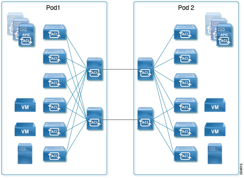
The following figures show two possible Multi-Pod Spines Back-to-Back topologies with back-to-back spines connected between Pod1 and Pod2. The first figure shows the recommended topology, with a full mesh interconnection between Pod1 spines and Pod2 spines. The second figure, showing a simpler interconnection between pods, is also supported.

Guidelines and Limitations for Multi-Pod Spines Back-to-Back
-
Only two Pods are supported with Multi-Pod Spines Back-to-Back links. If you need to add a third pod, you must use the full Cisco ACI Multi-Pod architecture with IPN core connectivity instead.
-
Cisco ACI Multi-Site, Cisco Nexus Dashboard Orchestrator, remote leaf switches, vPod, Cisco APIC cluster connectivity to the fabric over a Layer 3 network, and GOLF are not supported with Multi-Pod Spines Back-to-Back. These features and any other feature that requires an IPN connection are not supported when two Pods are connected with back-to-back spine links. IPN links and back-to-back spine links can coexist only during migration from one topology to the other, and data integrity is not guaranteed during that time.
-
As with IPN links, redundant links are recommended, but not all spines in each pod are required to have inter-pod links.
-
A spine switch with a Multi-Pod Spines Back-to-Back connection must have an active leaf-facing link (LLDP must be up). Otherwise, it is deemed unused and cannot be used by the fabric.
-
At least one spine switch must be configured with a BGP EVPN session for peering with spines in the remote pod.
-
In a Multi-Pod Spines Back-to-Back connection, if a spine link in one pod has MultiPod Direct enabled but the connected spine link in the other pod does not, OSPF neighborship might be established but no forwarding will occur. A fault is generated for this mismatch.
-
MACsec from spine ports is supported for Multi-Pod Spines Back-to-Back connections.
-
Migration to a Multi-Pod Spines Back-to-Back topology is disruptive, as is migration from a Multi-Pod Spines Back-to-Back topology to an IPN topology.
-
After migrating to Multi-Pod Spines Back-to-Back, you should remove any IPN links. If both IPN links and Multi-Pod Spines Back-to-Back links are present, the system will use the Multi-Pod Spines Back-to-Back links, but we do not recommend having IPN links in the Multi-Pod Spines Back-to-Back topology.
-
For a Multi-Pod Spines Back-to-Back configuration, the back-to-back links are treated as fabric links. You must create a MACsec fabric policy when enabling MACsec on the spine back-to-back links.
For information about creating a MACsec fabric policy, see the "Configuring MACsec for Fabric Links Using the GUI" procedure in the Cisco APIC Layer 2 Networking Configuration Guide.
-
Both back-to-back links must use the same MACsec policy. If you used pod polices, then both pods should deploy the same MACsec policy.
-
Multi-Pod back-to-back spines must be configured with OSPF network type Point-to-Point.
-
First generation spine switches are not supported.
Preparing APIC for Multi-Pod Spines Back-to-Back
Before configuring Multi-Pod Spines Back-to-Back, perform the general APIC configuration described in the following sections.
Define the Multi-Pod environment
In a Multi-Pod setup, you define a TEP pool for each Pod. The leaf and spine switches in each Pod are assigned TEP addresses from the Pod's TEP pool.
Establish the Interface Access Policies for the Second Pod
You can reuse the access policies of Pod1 only if the back-to-back spine interfaces on Pod1 and Pod2 are the same. In some cases, the spine interfaces connecting the two pods will not be the same because Pod2 may have a smaller spine. If the spine interfaces in both Pods are the same and the ports in all the switches are also the same, you need only to add the spine switches in Pod2 to the switch profile that you have defined for the spines in Pod1.
Configuring the Multi-Pod Spines Back-to-Back Interface
Cisco APIC provides a wizard to configure the Multi-Pod Spines Back-to-Back connection. The wizard configures the following components:
-
An L3Out interface in the infra tenant specifying the spine nodes and interfaces for the back-to-back links.
-
An internal TEP pool to be assigned to the remote Pod (Pod2).
-
An external TEP pool to be assigned to each Pod. The external TEP pool provides the Data Plane TEP IP used for MP-BGP EVPN forwarding across Pods. The pool is also used to assign an anycast TEP address to each Pod.
 Note |
Alternatively, you can configure the necessary infra L3Out interfaces without the Add Pod wizard. Follow the instructions in the "Multi-Pod" chapter of the Cisco APIC Layer 3 Networking Configuration Guide for the Create L3Out procedure, making sure to enable the MultiPod Direct setting in the configuration. |
Before you begin
-
The first Pod (Pod1) in the ACI fabric has already been successfully brought up.
-
The spine nodes in Pod2 have been powered up and are physically connected to the Pod1 spines with direct links. Cisco recommends the use of full mesh connections between the spine nodes deployed in the two Pods for redundancy and for better traffic convergence in link/node failure scenarios.
-
The leaf nodes in Pod2 have been powered up and properly cabled to connect with spine nodes in Pod2.
-
The Multi-Pod Spines Back-to-Back wizard is enabled for adding a second Pod.
Note
The Multi-Pod Spines Back-to-Back wizard is disabled in the following situations:-
Multiple Pods already exist in the fabric.
To migrate a two-pod fabric to Multi-Pod Spines Back-to-Back, follow the procedure in Migrating From an IPN to a Multi-Pod Spines Back-to-Back Topology.
-
The fabric is configured for Multi-Site, Remote Leaf, or vPod.
-
Procedure
|
Step 1 |
On the APIC GUI menu bar click . |
|
Step 2 |
In the Navigation pane, expand Quick Start and click Add Pod. |
|
Step 3 |
In the Add Pod pane of the working pane, click Add MPod B2B. The Add Pod wizard appears. |
|
Step 4 |
In the 1: IP Connectivity page, select the Pod1 spine nodes and their specific interfaces for connecting to the Pod2 spine nodes. Assign IP addresses to the interfaces. Perform the following actions:
|
|
Step 5 |
In the 2: Routing Protocol page, configure the OSPF routing protocol options for the back-to-back connections. Perform the following actions: |
|
Step 6 |
In the 3: Add Pod page, configure the interface settings for the remote Pod (Pod2). Perform the following actions: |
|
Step 7 |
In the 4: External TEP page, perform the following actions for each Pod:
|
|
Step 8 |
In the 5: Confirmation page, review the Pod details and the list of policies the wizard will create. Perform the following actions: |
|
Step 9 |
Click Save. The infra configuration required to connect Pod2 is complete, and the auto-discovery process begins. |
 ) to the right of the External TEP pane.
What to do next
Perform the registration procedure in Registering the Second Pod Nodes to register the Pod2 spines and switches.
Registering the Second Pod Nodes
With the links established between the Pods, the auto-discovery process finds all spine and leaf nodes in Pod2. As each node is discovered, you must register the node so that its configuration can be dynamically provisioned.
Before you begin
-
The Multi-Pod Spines Back-to-Back connection has been configured as described in Configuring the Multi-Pod Spines Back-to-Back Interface.
-
The Pod2 spine and leaf nodes are powered on and ready to be discovered.
Procedure
|
Step 1 |
On the APIC GUI menu bar click . |
|
Step 2 |
In the Navigation pane, choose Fabric Membership. |
|
Step 3 |
In the work pane, click the Nodes Pending Registration tab. |
|
Step 4 |
In the Nodes Pending Registration table, locate a switch with an ID of 0 or a newly connected switch with the serial number you want to register. |
|
Step 5 |
Right-click the row of that switch, choose Register, and perform the following actions:
|
|
Step 6 |
Repeat the registration for each Pod2 node in the Nodes Pending Registration table. When you have completed the registration, the spines in Pod1 should have successfully established OSPF peering with the directly connected spines in Pod2. |
What to do next
-
Run the setup script on any APIC node connected to a leaf node in Pod2.
-
Verify the configuration using the procedure in Verifying the Multi-Pod Spines Back-to-Back Configuration.
Verifying the Multi-Pod Spines Back-to-Back Configuration
Follow the steps in this section to verify the preceding configuration.
Verifying Fabric Membership and Topology
In the Cisco Application Policy Infrastructure Controller (APIC) GUI, go to . In the Fabric Membership list, verify that the spine switches are in an Active state and have their TEP addresses, which allowed discovery of the connected leaf switches.
Verifying OSPF Neighborship on Back-to-Back Links
Establish an SSH connection to the Pod1 spine nodes and verify that the OSPF neighborship is up as shown below.
Pod1-Spine1# vsh -c "show ip ospf multipodDirect neighbors vrf overlay-1"
 OSPF Process ID multiPodDirect VRF overlay-1
 Total number of neighbors: 1
 Neighbor ID     Pri State            Up Time  Address         Interface
 192.168.11.201   1 FULL/ -          00:17:01 192.168.1.2       Eth1/23.54


Pod1-Spine2# vsh -c "show ip ospf multipodDirect neighbors vrf overlay-1"
 OSPF Process ID multiPodDirect VRF overlay-1
 Total number of neighbors: 1
 Neighbor ID     Pri State            Up Time  Address         Interface
 192.168.11.201   1 FULL/ -          00:17:18 192.168.1.10       Eth2/21.57
Verifying Spine MP-BGP EVPN
Establish an SSH connection to each spine switch and verify the MP-BGP EVPN peering and route advertisements. The learned routes represent endpoints learned between the two pods. In the summary command, the number of learned routes will increase as the number of endpoints in the fabric increases.
Pod1-Spine1# show bgp l2vpn evpn summary vrf overlay-1
BGP summary information for VRF overlay-1, address family L2VPN EVPN
BGP router identifier 192.168.10.201, local AS number 100
BGP table version is 3059, L2VPN EVPN config peers 1, capable peers 1
185 network entries and 196 paths using 33664 bytes of memory
BGP attribute entries [6/1056], BGP AS path entries [0/0]
BGP community entries [0/0], BGP clusterlist entries [0/0]

Neighbor        V    AS MsgRcvd MsgSent   TblVer  InQ OutQ Up/Down  State/PfxRcd
192.168.11.201  4   100     103     249     3059    0    0 00:20:37 54
Configuring Multi-Pod Spines Back-to-Back Using the REST API
The Multi-Pod Direct flag in the APIC GUI is implemented in the object model by the Boolean isMultiPodDirect attribute of the infra tenant's L3Out path object l3extRsPathL3OutAtt. The default is False, indicating that the L3Out connection is not a Multi-Pod Spines Back-to-Back link.
The following configuration example shows two infra L3Out interfaces configured as Multi-Pod Spines Back-to-Back links.
<polUni>
  <fvTenant name="infra">
    <l3extOut name="multipod" status="">
      <bgpExtP />
      <ospfExtP areaCost="1" areaId="0" areaType="regular" />
      <l3extRsEctx tnFvCtxName="overlay-1" />
      <l3extLNodeP name="lnp1">
        <l3extRsNodeL3OutAtt rtrId="192.168.10.102" rtrIdLoopBack="no" tDn="topology/pod-1/node-102" />
        <l3extInfraNodeP fabricExtCtrlPeering="yes" fabricExtIntersiteCtrlPeering="no" status="" />
        </l3extRsNodeL3OutAtt>
        <l3extRsNodeL3OutAtt rtrId="192.168.10.202" rtrIdLoopBack="no" tDn="topology/pod-2/node-202">
          <l3extInfraNodeP fabricExtCtrlPeering="yes" fabricExtIntersiteCtrlPeering="no" status="" />
        </l3extRsNodeL3OutAtt>
        <l3extLIfP name="portIf">
          <ospfIfP authKeyId="1" authType="none">
            <ospfRsIfPol tnOspfIfPolName="ospfIfPol" />
          </ospfIfP>
          <l3extRsPathL3OutAtt addr="10.0.254.233/30" encap="vlan-4" ifInstT="sub-interface" tDn="topology/pod-2/paths-202/pathep-[eth5/2]" isMultiPodDirect="yes" />
          <l3extRsPathL3OutAtt addr="10.0.255.229/30" encap="vlan-4" ifInstT="sub-interface" tDn="topology/pod-1/paths-102/pathep-[eth5/2]" isMultiPodDirect="yes" />
        </l3extLIfP>
      </l3extLNodeP>
      <l3extInstP name="instp1" />
    </l3extOut>
  </fvTenant>
</polUni>
Migration Scenarios
Migrating From an IPN to a Multi-Pod Spines Back-to-Back Topology
Note |
Migrating between IPN-based and Multi-Pod Spines Back-to-Back topologies is a major change in your network design. Migration is disruptive, causes traffic loss, and should be done only during a maintenance window. |
When migrating from IPN-connected Pods to a Multi-Pod Spines Back-to-Back topology, follow these steps:
Before you begin
-
The Cisco ACI Multi-Pod fabric is running successfully with an IPN core network.
-
The fabric has only two pods.
-
The fabric does not have Cisco ACI Multi-Site/Cisco Nexus Dashboard Orchestrator, remote leaf, or vPod configured.
-
For every spine switch in each pod, individual logical node profiles exist under Tenants > infra > L3Outs. This is optional, but recommended for better manageability.
Procedure
|
Step 1 |
Connect the Multi-Pod Spines Back-to-Back links between pods. These links are discovered by LLDP. |
|
Step 2 |
Add logical interface profiles for the back-to-back interfaces, starting with Pod1 interfaces and followed by Pod2 interfaces. |
|
Step 3 |
Establish an SSH connection to the Pod1 spine node and verify that OSPF neighborship is formed between the back-to-back spine interfaces in addition to the existing OSPF neighborship with the IPN device. Use the CLI command shown in the following example: |
|
Step 4 |
For each logical interface profile that contains an IPN link configuration, save the profile for later use. When saved, you can restore the logical interface profile if you need to migrate back to an IPN in the future. |
|
Step 5 |
When OSPF sessions are established, remove the IPN-connected logical interface profiles from and remove the IPN links. Cisco ACI Multi-Pod traffic will move to the back-to-back links. |
|
Step 6 |
Verify that all devices are reachable between pods by using the |
|
Step 7 |
Verify inter-pod communication. |
Migrating From a Multi-Pod Spines Back-to-Back Topology to an IPN
Note |
Migrating between IPN-based and Multi-Pod Spines Back-to-Back topologies is a major change in your network design. Migration is disruptive, causes traffic loss, and should be done only during a maintenance window. |
When migrating from a Multi-Pod Spines Back-to-Back topology to an IPN connection, follow these steps:
Before you begin
-
The Cisco ACI Multi-Pod fabric is running successfully with Multi-Pod Spines Back-to-Back back-to-back spine connections.
-
If, you saved the IPN-connected logical interface profiles for every spine switch in each pod before migrating to Multi-Pod Spines Back-to-Back, have those saved files available.
Procedure
|
Step 1 |
Connect the IPN links between pods. These links are discovered by LLDP, but Cisco ACI Multi-Pod traffic continues to use the Multi-Pod Spines Back-to-Back links. |
||
|
Step 2 |
On the menu bar, choose . |
||
|
Step 3 |
In the Navigation pane, choose . |
||
|
Step 4 |
If you saved the IPN-connected logical interface profiles before migrating to Multi-Pod Spines Back-to-Back, then for each logical interface profile that will connect a spine to the IPN, right-click the profile in the Navigation pane and choose Post ... to upload the previously-saved logical interface profile file. Upload the file that you saved in Migrating From an IPN to a Multi-Pod Spines Back-to-Back Topology for the specific interface. |
||
|
Step 5 |
If you did not save the IPN-connected logical interface profiles before migrating to Multi-Pod Spines Back-to-Back, configure the IPN-facing interfaces for each spine connected to the IPN network in the respective logical interface profiles. |
||
|
Step 6 |
Configure any other required settings for IPN, such as Cisco ACI Multi-Pod QoS translation. For information about configuring Cisco ACI Multi-Pod with IPN, see the Cisco ACI Multi-Pod White Paper and the "Multi-Pod" chapter of the Cisco APIC Layer 3 Networking Configuration Guide. |
||
|
Step 7 |
Verify that the IPN network nodes are configured properly and OSPF neighborship is up on the IPN nodes for both the Pod spines. At this time, OSPF neighborship is active for both IPN and back-to-back interfaces, both learning the remote TEP addresses for Pod2. |
||
|
Step 8 |
Remove the Multi-Pod Spines Back-to-Back back-to-back interfaces from Pod1, followed by Pod2. Multi-Pod traffic will move to the IPN links.
|
||
|
Step 9 |
Verify that all devices are reachable between pods by using the |
||
|
Step 10 |
Verify inter-pod communication. |
 Feedback