Validated Profile: Transportation – Airport (SD-Access) Vertical
Available Languages
Bias-Free Language
The documentation set for this product strives to use bias-free language. For the purposes of this documentation set, bias-free is defined as language that does not imply discrimination based on age, disability, gender, racial identity, ethnic identity, sexual orientation, socioeconomic status, and intersectionality. Exceptions may be present in the documentation due to language that is hardcoded in the user interfaces of the product software, language used based on RFP documentation, or language that is used by a referenced third-party product. Learn more about how Cisco is using Inclusive Language.
- US/Canada 800-553-2447
- Worldwide Support Phone Numbers
- All Tools
 Feedback
 Feedback
Document Purpose and Usage
The purpose of this document is to outline the typical transportation deployment profile that Cisco recommends. It provides guidelines for a typical nonfabric deployment that uses Catalyst Center and also serves as a validation document you can refer to during the process. This document's theoretical sections should be used in conjunction with its practical sections to help a deployment engineer understand the service requirements. The document will also help the deployment engineer make the best decisions for their particular network during deployment and configuration.
Target Audience
The target audience for this transportation profile is the technical staff that is responsible for engineering and operating the network, as well as the implementation teams.
Solution Overview
This document provides guidance and can be used as a design reference for a typical airport transportation network deployment using Catalyst Center and Cisco Software-Defined Access.
Airport networks play a pivotal role in supporting critical airport applications and diverse services, offering managed solutions for airlines and vendors. Maintaining a high level of reliability is imperative for essential operations like flight scheduling, baggage handling, and security systems. Scalability is crucial to meet the rising demands of connected devices and data. Logical separation of network segments enhances security and facilitates efficient management by isolating services, departments, or applications. Additionally, extensive use of wireless technologies is integral for connectivity across various airport services, including passenger Wi-Fi, operational devices, and IoT sensors. However, airports face numerous challenges in their network architecture, stemming from the necessity of end-to-end segmentation for security, compliance requirements, and daily network service management with a security focus. Geographically dispersed networks necessitate resilience at both network and service levels. The integration of IT and OT, coupled with the complexity of business processes, people, technology, and digital twins, presents unique challenges. Security compliance mandates, particularly in safeguarding sensitive passenger information, drive the demand for regulation-compliant wired and wireless networks, requiring macrosegmentation and microsegmentation capabilities. Challenges include staff and device mobility, reliance on IoT endpoints, high availability, resiliency, passenger safety, and asset tracking, contributing to operational complexity. IT staff faces challenges in managing the increasing number of devices, navigating security requirements, dealing with IP-based rule management, and troubleshooting difficulties without onsite support.
Various applications are integral to airport operations, encompassing a diverse range of functions. These include airline check-in systems; flight information display systems; passenger screening; robots employed for various tasks; airport operation command center user machines; gate operation systems; public announcement systems; aviation control systems; location analytics for efficient navigation; kiosks for user interaction; CCTV cameras and monitoring systems for security surveillance; access control systems; attendance systems; scanners, phones, and printers for streamlined processes; digital signage for information dissemination; baggage handling systems; logistics systems; and Wi-Fi connectivity to facilitate seamless connectivity throughout the airport infrastructure. Each of these applications plays a crucial role in ensuring the smooth and secure functioning of airport facilities.
To transform the airport into a smart facility and achieve a comprehensive set of goals, a strategic approach involves several key initiatives. Digitally transforming the airport requires the integration of cutting-edge technologies and innovative solutions. Building a multitenant network is essential for accommodating various stakeholders and applications within the airport ecosystem. Enhancing both passenger and worker experiences involves implementing smart technologies like automated check-in systems, real-time flight information displays, and personalized services. Expanding connectivity to rugged and outdoor areas ensures seamless communication and data exchange in all airport zones, including aprons and maintenance areas. Meeting compliance and regulatory goals requires secure and regulatory-compliant wired and wireless networks, incorporating macro segmentation and micro segmentation capabilities to safeguard sensitive information. Improving operations is achieved through the creation of a more connected and secure environment, with the integration of smart technologies like IoT devices for real-time monitoring, control, and data analytics. The construction of a smart airport involves a holistic digital transformation, building a robust multitenant network, enhancing user experiences, extending connectivity to outdoor areas, meeting compliance standards, and ultimately optimizing operations within a secure and connected environment.
Cisco offers a comprehensive suite of solutions designed to facilitate the development of a smart airport infrastructure. Leveraging Cisco's Intent-Based Networking (IBN), airports can achieve intelligent automation, ensuring efficient network management and enhanced security. Catalyst Center provides a centralized platform for unified network management, while Cisco SD-Access facilitates flexible and secure access policies. For wireless connectivity, Cisco's wireless solution incorporates the Cisco Catalyst 9800 series and Wi-Fi 6 Access Points, ensuring high-performance and reliable wireless communication throughout the airport. The Cisco Next Generation Firewall – Firepower enhances security with advanced threat protection and intrusion prevention capabilities. Identity management is streamlined through the Cisco Identity Services Engine (ISE), offering secure and policy-driven access control. Cisco Application Centric Infrastructure (ACI) provides a dynamic and programmable network infrastructure, optimizing the delivery of applications and services. To enhance user experiences and engagement, Cisco Spaces Captive Portal offers a customizable portal for seamless connectivity. Monitoring and analytics are supported by solutions like ThousandEyes and ServiceNow, providing real-time insights into network performance and user interactions.
Cisco SD-Access represents a shift from traditional enterprise network designs to networks aligned with an organization's intent. Cisco SD-Access operates through an application package within the Catalyst Center software, facilitating the design, provisioning, policy application, and creation of an intelligent airport network. Cisco SD-Access incorporates fabric technology, allowing programmable overlays and network virtualization in wired and wireless networks.
Cisco SD-Access offers several advantages for airport networks. It allows the utilization of edge data to enhance operational insights and optimize processes. The solution enables the creation of new digital experiences for customers, thereby enhancing overall satisfaction. Digitizing the airport infrastructure using Cisco SD-Access opens avenues for generating additional revenue. The centralized management of the enterprise network contributes to reduced operating expenses (OpEx). The solution focuses on simplifying, securing, and providing control over the IT-run airport environment.
Scope of the Document
This document serves as a reference for common use cases, challenges, and how Cisco SD-Access addresses these requirements in airport deployments. Although it doesn’t provide step-by-step instructions to configure, it serves as a valuable reference for understanding the solutions available.
Traditional Networks Versus Cisco SD-Access
The following sections discuss the challenges of traditional network architectures and how Cisco SD-Access can address them.
Challenges in Traditional Networks
Organizations deploying traditional network architectures face mounting challenges as the number of users, devices, and types of devices continue to grow. Identifying, grouping, and analyzing the traffic of all the users and devices is a significant concern for organizations that want to ensure they do not impact their corporate infrastructure should a device or network device become compromised. In traditional networks, the need for many VLANs and manual Access Control Lists (ACLs) across multiple and often disparate devices becomes a recipe for manual misconfiguration disasters. As time goes on and the business expands, more devices and locations are added to increasing complexity and the possibility for errors. New and more complex security rules must be manually updated across the enterprise.
When the organization adds a new branch to the enterprise, the network operations team will need to update the ACLs in both the headquarters (HQ) and branch locations. If an error is made during the update, then the security policy becomes inconsistent and could result in a security breach. Network administrators must spend significant and arduous time planning and configuring network changes to ensure that every device is securely onboarded onto the network using the proper network segment. The traditional ways of building a network do not cater to the requirements of an evolving network and ever-growing security concerns.
The Importance of Cisco SD-Access
Cisco SD-Access is built on an intent-based networking foundation that encompasses visibility, automation, security, and simplification. Using Catalyst Center automation and orchestration, network administrators can implement changes across the entire enterprise environment through an intuitive, UI interface. Using the same controller, they can build enterprise-wide fabric architectures, classify endpoints for security grouping, create and distribute security policies, and monitor network performance and availability.
SD-Access secures the network at the macrosegmentation and microsegmentation levels using Virtual Routing and Forwarding (VRF) tables and Security Group Tags (SGTs), respectively. This is called multi-tier segmentation, which is not optimal in traditional networks. The security boundary is pushed to the very edge of the network infrastructure for both wired and wireless clients.
The security contexts associated with a user or a device are dynamically assigned when they authenticate their network connection. Cisco SD-Access is superior to traditional network deployments because of the following reasons:
● Complexity reduction and operational consistency through orchestration and automation.
● Multitier segmentation, which includes group-based policies.
● Dynamic policy mobility for wired and wireless clients.
Greenfield Cisco SD-Access Fabric Guidelines
For guidelines and recommendations on a new deployment (greenfield deployment) of Cisco SD-Access fabric for an airport network, continue to the following sections. These sections explain the SD-Access fabric components and the benefits that Cisco SD-Access solutions offer to address the airport network requirements and challenges.
Traditional networks can be managed by Cisco Prime Infrastructure. They can also be managed now with Catalyst Center. Catalyst Center can be used to automate, monitor, and gather telemetry for traditional networks as well as SD-Access. If you have an existing network managed by Cisco Prime Infrastructure and are looking to migrate to Catalyst Center, refer to the Cisco Prime Infrastructure to Cisco Catalyst Center Migration Validated Profile.
Cisco Catalyst Center
Catalyst Center is a powerful management system that leverages Artificial Intelligence (AI) to connect, secure, and automate network operations. Catalyst Center simplifies management of Cisco Catalyst network infrastructure and ensures a consistent user experience across wired and wireless networks. It delivers enterprise-scale, secure, seamless, and reliable connectivity among users, applications, and things. Benefits include:
● Leverage AI to simplify and automate network operations, which helps reduce operational costs.
● Improve user experience with deep insights into business-critical applications and client health.
● Accelerate digital agility through business process automation using Cisco and third-party ecosystem.
● Secure the digital enterprise with intuitive security policy management, AI-enabled enforcement, and automated compliance checks.
● Drive sustainability by enabling smart buildings and optimizing Power over Ethernet (PoE) infrastructure.
The Catalyst Center platform is supported in different form factors as both a physical appliance and virtual appliance.
See the Cisco Catalyst Center Data Sheet for a complete supported platform and scale. See also the Cisco Catalyst Center Installation Guides.
Cisco Identity Services Engine
Cisco Identity Services Engine (ISE) is a secure network access platform enabling increased management awareness, control, and consistency for users and devices accessing an organization's network. ISE is an integral and mandatory part of SD-Access for implementing network access control policy. ISE performs policy implementation, enabling dynamic mapping of users and devices to scalable groups, and simplifying end-to-end security policy enforcement. Catalyst Center is used as the pane of glass to manage and create SGTs (scalable group tags) and define their policies. Group and policy services are driven by ISE and orchestrated by Catalyst Center's policy authoring workflows. Policy management with identity services is enabled in an SD-Access network using ISE integrated with Catalyst Center for dynamic mapping of users and devices to scalable groups. This simplifies end-to-end security policy management and enforcement at a greater scale than traditional network policy implementations relying on IP access-lists.
Cisco ISE supports standalone and distributed deployment models. Multiple, distributed nodes can be deployed together to provide failover resiliency and scale. The range of deployment options allows support for hundreds of thousands of endpoint devices. Minimally, a basic two-node Cisco ISE deployment is recommended for SD-Access single site deployments with each Cisco ISE node running all services (personas) for redundancy.
For details on Cisco ISE deployment models, refer to the Cisco Identity Services Engine Administrator Guide. See also the Cisco ISE Performance and Scalability Guide.
Cisco Catalyst 9000 Series Switches
Cisco Catalyst 9000 series switching offers more flexible and highly scalable design options. Switches supported in different fabric roles offer secure, fast, and reliable connectivity to users and endpoints within the network. For details, refer to the data sheet for Catalyst 9000 switches.
Cisco Catalyst Wireless LAN Controller and Access Point
Cisco Catalyst 9800 Series Wireless LAN Controllers (WLC) and Access Points (AP) provide seamless network management and deployment in both on-premises and cloud for wireless clients. For the complete data sheet of Catalyst 9800 and Catalyst 9100 devices, refer to:
● Cisco Access Point and Wireless Controller Selector
Cisco SD-Access Fabric
Cisco Software-Defined Access (SD-Access) is the evolution from traditional campus LAN designs to networks that explicitly implement an organization's intent. SD-Access is a software solution used to automate wired and wireless campus networks. Fabric technology, an integral part of SD-Access, provides wired and wireless campus networks with programmable overlays and easy-to-deploy network virtualization, allowing a physical network to host one or more logical networks to meet the design intent.
In addition to network virtualization, fabric technology in the campus network enhances control of communications, providing software-defined segmentation and policy enforcement based on user identity and group membership. Software defined segmentation is seamlessly integrated using Cisco TrustSec, providing micro-segmentation for groups within a virtual network using scalable group tags (SGTs). Using Cisco Catalyst Center to automate the creation of virtual networks with integrated security and segmentation reduces operational expenses and reduces risk. Network performance, network insights, and telemetry are provided through the Assurance and Analytics capabilities. Cisco SD-Access provides policy mobility for both wired and wireless clients.
Fabric Architecture Overview
The following sections provide an overview of the Cisco SD-Access architecture and solution components.
Solution Components
The Cisco SD-Access solution is provided through a combination of Catalyst Center, the Cisco Identity Services Engine (Cisco ISE), and the wired and wireless device platforms which have fabric functionality. As described later in the Fabric Roles section, the wired and wireless device platforms are used to create the elements of a fabric site. Catalyst Center software, including the SD-Access application package, runs on the Catalyst Center hardware appliance.
Operational Planes
● Control Plane: Messaging and communication protocol between infrastructure devices in the fabric.
● Data Plane: Encapsulation method used for the data packets.
● Policy Plane: Used for security and segmentation.
● Management Plane: Orchestration, assurance, visibility, and management.
In SD-Access, the control plane is based on Locator/ID Separation Protocol (LISP), the data plane is based on Virtual Extensible LAN (VXLAN), the policy plane is based on Cisco TrustSec, and the management plane is enabled and powered by Catalyst Center.
Network Architecture
The SD-Access architecture is supported by fabric technology implemented for the campus, enabling the use of virtual networks (overlay networks) running on a physical network (underlay network) creating alternative topologies to connect devices. In SD-Access, the user-defined overlay networks are provisioned as VRF instances that provide separation of routing tables.
Fabric Roles
A fabric role is an SD-Access software construct running on physical hardware. See the Cisco SD-Access Compatibility Matrix for the hardware models supported for different fabric roles.
● Control Plane Node
The SD-Access fabric control plane node is based on the LISP Map-Server and Map-Resolver functionality combined on the same node. The control plane node’s database tracks all endpoints in the fabric site and associates the endpoints to fabric nodes, decoupling the endpoint IP address or MAC address from the location (closest router) in the network.
● Edge Node
The SD-Access fabric edge nodes are the equivalent of an access layer switch in a traditional campus LAN design. Edge node provides endpoint registration locally and updates the control plane node. It provides the Anycast Layer 3 gateway for the hosts to connect to the fabric network and acts as an authentication relay agent for the hosts.
● Intermediate Node
Intermediate nodes are part of the Layer 3 network used for interconnections among the devices operating in a fabric role such as the interconnections between border nodes and edge nodes. These nodes provide IP reachability, physical connectivity, and support the added MTU requirement to accommodate the larger-sized IP packets encapsulated with fabric VXLAN information.
● Border Node
Fabric border nodes serve as the gateway between the SD-Access fabric site and the networks external to the fabric. The border node can extend network virtualization from inside the fabric to outside of the fabric by using VRF-lite and VRF-aware routing protocols to preserve the segmentation. This may be a single switch, a switch with hardware stacking, or a StackWise Virtual deployment.
● Fabric in a Box
Fabric in a box is an SD-Access construct where the border node, control plane node, and edge node are running on the same fabric node. This may be a single switch, a switch with hardware stacking, or a StackWise Virtual deployment.
For more information on StackWise Virtual deployment, refer to the Cisco Catalyst 9000 Platform StackWise Virtual White Paper.
● Extended Node
SD-Access extended nodes offer the ability to extend the enterprise network by providing connectivity to non-carpeted spaces of an enterprise – commonly called the Extended Enterprise. Extended nodes offer a Layer 2 port extension to a fabric edge node while providing segmentation and group-based policies to the endpoints connected to these switches. For detailed extended node design, refer to the Cisco SD-Access Solution Design Guide.
● Fabric Wireless Controller and Access Points
Fabric wireless controllers and nonfabric wireless controllers provide AP image and configuration management, client session management, and mobility services. Fabric wireless controllers provide added services for fabric integration such as registering MAC addresses of wireless clients into the host tracking database of the fabric control plane nodes. The fabric-mode APs are Cisco Wi-Fi 6 (802.11ax) and 802.11ac Wave 2 APs associated with the fabric wireless controller that have been configured with one or more fabric-enabled SSIDs. Fabric-mode APs continue to support the same wireless media services that traditional APs support such as applying AVC, quality of service (QoS), and other wireless policies.
For more information and details on wireless operations and communications with SD-Access wireless, fabric wireless controllers, and fabric APs, refer to the SD-Access Wireless Design and Deployment Guide.
● SD-Access Embedded Wireless
Wireless controller functionality without a hardware wireless controller in distributed branches and small campuses can be achieved with the Cisco Catalyst 9800 Embedded Wireless Controller for Catalyst 9000 Series Switches as a software package. The Cisco Catalyst 9800 Embedded Wireless Controller for Catalyst 9000 Series Switches is supported for SD-Access deployments with the following three topologies:
◦ Cisco Catalyst 9000 Series switches functioning as collocated border and control plane.
◦ Cisco Catalyst 9000 Series switches functioning as an edge node when the border and control plane nodes are on a routing platform.
◦ Cisco Catalyst 9000 Series switches functioning as a fabric in a box.
● Transit and Peer Network
Transit and peer network are SD-Access constructs that define how Catalyst Center automates the border node configuration for the connections between fabric sites or between a fabric site and the external world. This connectivity may be MAN, WAN, or Internet. There are two distinct types of transit networks available in the SD-Access fabric namely SDA transit and IP transit to connect distributed campuses and the external network.
● Transit Control Plane Nodes
Transit control plane nodes are a fabric role construct supported in SD-Access for distributed campus. It works in the same manner as a site-local control plane node except it services the entire fabric. Transit control plane nodes are needed only when using SD-Access transits. See also the Software-Defined Access for Distributed Campus Deployment Guide.
You can find detailed information on Cisco SD-Access components and architecture here.
High Availability
Cisco SD-Access High Availability (HA) refers to the design and implementation of features and mechanisms that ensure the continuous and reliable operation of the SDA solution. HA is crucial for minimizing downtime and maintaining network functionality, especially in critical environments like airport networks.
Cisco SD-Access HA aims to create a robust and resilient network infrastructure by combining redundancy, failover mechanisms, load balancing, health monitoring, and fast convergence. These features collectively contribute to ensuring continuous and reliable network services, even in the face of unexpected events or hardware or software failures.
The airport SDA network incorporates the following HA components:
● Three-Node Catalyst Center Cluster
Catalyst Center is configured as a three-node cluster. This clustering approach enhances scalability, load distribution, and provides failover capabilities, ensuring continuous operation in the event of a node failure.
● Distributed Cisco ISE Cluster
Cisco ISE has a highly available and scalable architecture that supports standalone and distributed deployments. In a distributed environment, redundant Policy Administration Node (PAN), monitor and Policy Service Node (PSN) are deployed. You can configure one primary administration ISE node to manage the secondary ISE nodes that are deployed in the network.
● FTD Firewall Failover Pair
Firepower Threat Defense (FTD) firewall is deployed in a failover pair configuration. In the event of a failure in one firewall, the standby firewall assumes the active role, preventing disruptions in network security services.
● Catalyst 9800 Series Wireless Controller SSO HA
Catalyst 9800 Series Wireless Controller is configured with Stateful Switch Over (SSO) HA. This ensures a smooth transition in case of a failure, maintaining wireless network services without interruption.
● Catalyst 9500 SVL Pair for Border and Control Plane
A pair of Catalyst 9500 Series switches is configured in StackWise Virtual Link (SVL) mode to handle border and control plane functions. This redundancy enhances the reliability of these critical network components.
● Catalyst 9600 Quad SUP SVL Pair for Border and Control Plane
For high-capacity requirements, a pair of Catalyst 9600 Series switches with Quad Supervisor Engines (SUPs) is configured in SVL mode to serve as the border and control plane node, providing both redundancy and performance.
● Catalyst 9300 Stacking Switch as Fabric Edge
Catalyst 9300 Series switches are configured in a stacking arrangement. Stacking allows these switches to operate as a single logical unit, providing high availability and simplifying management.
● Catalyst 9400 Dual Supervisor as Fabric Edge
Catalyst 9400 Series switches are equipped with dual SUPs to ensure high availability at the fabric edge. The dual SUPs provide redundancy and facilitate uninterrupted operation in case of a SUP failure.
These mechanisms collectively contribute to a resilient and highly available network infrastructure in the Catalyst Center's SD-Access environment, minimizing the impact of potential failures and enhancing the overall reliability of the network.
ThousandEyes
Cisco ThousandEyes is a comprehensive network intelligence platform designed to provide organizations with insights into network performance, internet visibility, and digital experiences. This platform enables the monitoring of internal infrastructure and internet-related performance, offering end-to-end visibility from the user device to the application server. Cisco ThousandEyes features path visualization, allowing organizations to understand and optimize network routes, and it supports cloud and Software as a Service (SaaS) monitoring to enhance the performance of services in these environments. With capabilities for alerting, analytics, and historical performance analysis, Cisco ThousandEyes empowers organizations to proactively manage and troubleshoot network issues, ensuring a robust and optimized digital experience for users. Keep in mind that product details may evolve, and for the latest information, it's advisable to consult Cisco's official documentation or contact Cisco directly.
For more information, refer to Cisco Thousand Eyes.
ServiceNow
ServiceNow is a cloud-based platform offering a comprehensive suite of applications for IT service management (ITSM), IT operations management (ITOM), and IT business management (ITBM). This versatile platform is designed to help organizations streamline and automate various business processes, thereby enhancing overall operational efficiency. Within its ITSM applications, ServiceNow supports processes such as incident management, problem management, change management, and service catalog management. In the realm of IT operations, the platform provides capabilities for service mapping, event management, cloud management, and orchestration. Additionally, ServiceNow's ITBM applications assist organizations in aligning IT resources with business objectives through project portfolio management, demand management, and financial management. With a focus on customer service, the Customer Service Management (CSM) applications offer tools for case management, knowledge management, and customer self-service portals. The platform extends its reach to Human Resources Service Delivery (HRSD) for automating HR processes, as well as Security Operations (SecOps) for integrating security incident and vulnerability response into the overall IT workflow. Known for its flexibility and scalability, ServiceNow is widely used across industries to improve service delivery, automate workflows, and foster collaboration across various business functions.
For more information, refer to the Cisco Catalyst Center ITSM Integration Guide.
Compatibility Matrix
Catalyst Center provides coverage for Cisco enterprise switching, routing, and mobility products. For a complete list of supported Cisco products, refer to:
● Cisco Catalyst Center Compatibility Matrix
● Cisco SD-Access Compatibility Matrix
Airport Profile Deployment
This section offers design guidance for deploying Cisco SD-Access airport network.
Cisco SD-Access Airport Network Topology
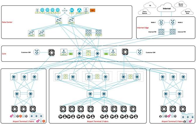
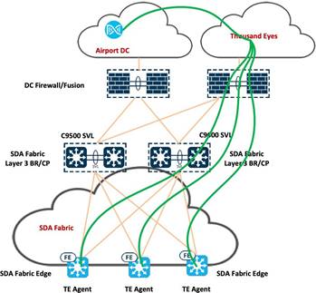
In the transportation topology, a three-node, 112-core Catalyst Center cluster is deployed. This cluster is integrated with a distributed Cisco ISE cluster, comprising of two PANs, two monitoring (MnT) nodes, a pxGrid, and multiple PSNs.
A pair of Cisco Firepower firewalls serve as Cisco SD-Access fusion devices for various virtual networks within the airport network. The Border Gateway Protocol (BGP) facilitates route exchange between the firewall and Cisco SD-Access border and control plane. Meanwhile, Open Shortest Path First (OSPF) operates between the Cisco ACI leaf and the firewall, where mutual redistribution is configured on the firewall between the OSPF and BGP.
Two pairs of Catalyst switches, utilizing Cisco SVL technology, form unified logical switches that act as the border and control plane within the airport fabric site. Both sets of switches are running the BGP with the fusion device (FTD firewall) and the Intermediate System-to-Intermediate System (IS-IS) with two intermediate switches. Another pair of Catalyst 9500 switches, utilizing Cisco SVL technology, form an additional logical switch that serve as the Layer 2 border within the same fabric. These switches connect airport vendors to their own network using the airport fabric. Two Catalyst switches act as intermediate switches that connect to both borders and fabric edges while running ISIS between them. The Catalyst 9300 stack and Catalyst 9400 switches function as fabric edges with user devices, cameras, and wireless APs connected to them.
The following figure illustrates the logical topology of the Transportation Vertical solution test bed.
Solutions to Airport Business Outcomes
The following sections describe the technologies that are used for deploying Cisco SD-Access in an airport network.
Layer 2 Border in the Airport Fabric
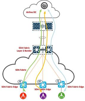
Cisco SD-Access (SDA) Layer 2 border is a crucial component within the SDA architecture. SDA is an intent-based networking solution that aims to simplify network management and enhance security by leveraging automation and policy-based segmentation. The Layer 2 border serves as a boundary within the SDA fabric, responsible for managing the communication between different virtual networks at Layer 2.
In Cisco SD-Access, nonlocal traffic from endpoints traditionally flows through a distributed Layer 3 anycast gateway located on all edge nodes within a fabric site. This gateway, implemented as a switched virtual interface (SVI), ensures optimal forwarding and mobility across various routing locators. However, for scenarios where IP addressing and default gateway are not managed by the airport network administrator, such as an airline and vendor’s network, the Layer 2 virtual network service provides pure Layer 2 connectivity without the need for a Layer 3 anycast gateway.
Using VLAN-based Layer 2 Virtual Network Identifiers (VNIs), SD-Access distinguishes and isolates virtual networks at Layer 2. Each virtual network receives a unique identifier, enabling multiple networks to coexist securely on the same underlay. This is particularly valuable when different tenants or applications share an environment but require logical separation. Layer 2 VNIs are similar to traditional VLANs in non-SD-Access networks, with Layer 2 overlays identified through a VLAN-to-VNI correlation.
Unlike Layer 3 overlays with a Virtual Routing and Forwarding (VRF)-to-VNI correlation, Layer 2 VNIs in SD-Access map to VLAN broadcast domains. Both Layer 2 and Layer 3 VNIs facilitate the isolation of data and control planes for individual virtual networks. Security Group Tags (SGTs) carry user group membership information, ensuring data plane segmentation within the virtualized network.
While deploying a Layer 3 virtual network mandates the use of VRF routing capabilities and precludes the flexibility of employing custom gateways, Layer 2 virtual networks offer a simpler alternative, providing similar outcomes with less complexity.
Within the transportation vertical, each airport has many tenants, such as retail shops, duty-free shops, food and beverage outlets, car rental agencies, travel agencies, currency exchange and banking services, technology and electronic stores, airlines and airlines services, and airport lounges that are utilizing the airport infrastructure to connect their devices back to their networks. Their default gateways are not on the fabric edge, instead they are located outside of the SDA fabric.
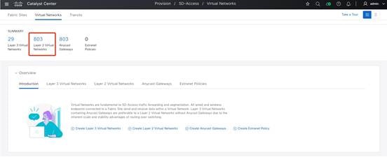
The following procedure provides an example of how to set up the Layer 2 virtual network for different vendors using Catalyst Center. In this example, two Layer 3 virtual networks are created on Catalyst Center: Vendor 1 and Vendor 2. 500 Layer 2 virtual networks are created under Vendor 1 and 300 Layer 2 virtual networks are created under Vendor 2, respectively.
Step 1. In the Catalyst Center GUI, click the menu icon and choose Provision > Virtual Networks.
Step 2. Navigate to the required Layer 2 virtual network.
Step 3. In the Fabric Infrastructure tab, choose the required Layer 2 border node and click the Configure option under the Fabric tab.
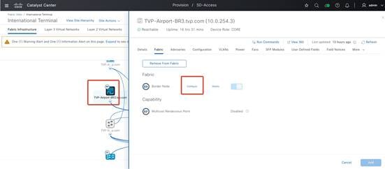 |
Step 4. Click the Layer 2 Handoff tab.
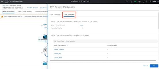
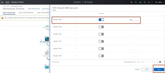
Step 5. Enable the Layer 2 virtual network for Vendor 1 and click Save.
 |
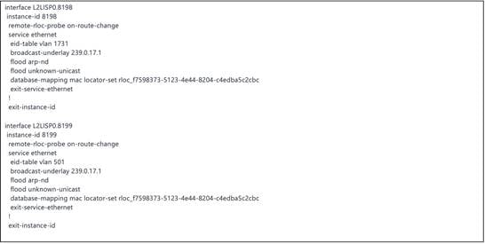
Layer 2 border LISP-related configurations are created and pushed from Catalyst Center to the fabric edges and Layer 2 borders, as shown in the following example.
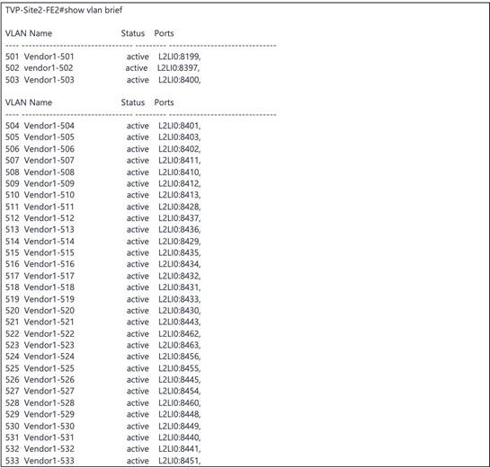
VLANs are created and pushed from Catalyst Center to the fabric edges and Layer 2 borders. The following example shows the VLANs configured on a fabric edge.
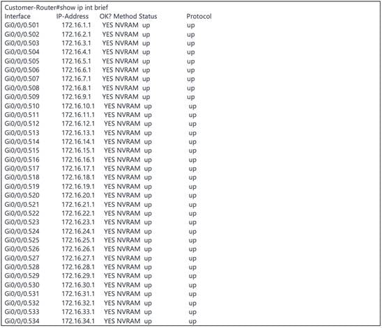
On the customer gateway, the subinterfaces (as shown in the following example) are created as gateways for all the VLANs.
Cisco Firepower 9300 as the SD-Access Fusion Device
Network segmentation plays a crucial role in safeguarding vital business assets. In SD-Access, security is seamlessly integrated into the network through segmentation. Segmentation involves separating specific groups of users or devices from others for security reasons. SD-Access employs two key types of segmentation: macrosegmentation and microsegmentation.
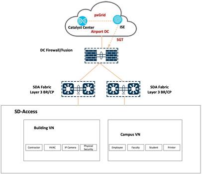
Macrosegmentation (Virtual Networks)
Macrosegmentation in SD-Access entails breaking down a single large network with a unified routing table into numerous smaller logical networks (segments or virtual networks). This process provides isolation between segments, reduces the attack surface, and introduces enforcement points between them. SD-Access facilitates secure network deployment for environments like airports by offering a straightforward approach to understanding, designing, implementing, and supporting networks. In the SD-Access fabric, the VXLAN network identifier (VNI) field carries information identifying the virtual network and SGT within the VXLAN-GPO header.
Macrosegmentation logically divides a network topology into smaller virtual networks using a unique network identifier and separate forwarding tables. This is realized as a VRF instance on switches or routers, referred to as a virtual network in Catalyst Center.
A virtual network within the SD-Access fabric is a logical network instance providing Layer 2 or Layer 3 services and defining a Layer 3 routing domain. The VNI field in the VXLAN header carries information identifying the virtual network within the SD-Access fabric, supporting both Layer 2 (Layer 2 VNI) and Layer 3 (Layer 3 VNI) segmentation.
LISP is employed within the SD-Access fabric to provide control plane forwarding information. The LISP instance ID ensures unique address spaces in the control plane, supporting virtualization. Externally, at the SD-Access border, virtual networks directly map to VRF instances, which can extend beyond the fabric.
This segmentation approach enhances security, simplifies network management, and enables scalable deployments in complex environments like airports.
Microsegmentation (SGT)
Cisco Group-Based Policy simplifies the way we manage security and flexibility in our network. Instead of dealing with complex technical details, we organize devices into groups based on their roles. These groups can be used across different parts of the network, making it easier to set up and manage security rules.
Think of it like sorting devices into user-friendly categories, such as the type of device or its role in the network. Unlike traditional methods that rely on complicated IP addresses, our approach uses these simple categories to define security rules. This makes it much easier for us to control and manage security measures.
The scalable groups, also known as security groups, provide valuable information about the devices, like their role, the applications they use, or even the threat level they pose. This additional insight helps us streamline the setup of firewall rules, web security policies, and access controls in various network devices, like switches and routers.
Cisco Group-Based Policy is straightforward to enable and manage, unlike older methods that involve complex VLAN-based segmentation. This simplicity not only makes our job easier but also avoids putting extra strain on our network devices.
In SD-Access, network segmentation occurs at both macro and micro levels using virtual networks and SGTs respectively. Virtual networks act as isolated domains within the SD-Access fabric, providing macrosegmentation between different virtual networks and allowing communication among devices within each virtual network. By default, devices within a virtual network can communicate with each other, but to facilitate communication between different virtual networks, an external device like a fusion router or firewall is necessary to handle inter-VRF forwarding. On a finer scale, microsegmentation is achieved through SGTs, enabling more granular control over communication within a virtual network. This approach ensures a structured and secure network environment within SD-Access.
A fusion device in SD-Access facilitates VRF leaking across fabric domains, enabling host connectivity to shared services like DHCP, DNS, NTP, ISE, Catalyst Center, and wireless LAN controllers in the data center or service block. While this role can be performed by various devices, this document focuses on the Cisco FTD routed mode firewall as a fusion device. To provide shared services to all virtual networks in the campus, BGP peerings are created between border nodes and the FTD firewall. The fusion device leaks fabric VRF subnets, requiring access to shared services, into the Global Routing Table (GRT) or a shared services VRF, and conversely.
This validation uses a virtual router on Cisco Firepower firewall for control plane and data plane separation. Virtual routers maintain separate routing tables for groups of interfaces on a single firewall.
 |
Multicast Design in the Airport Network
In networking, multicast is a communication method that allows one-to-many or many-to-many communication. It is particularly useful in scenarios where multiple devices need to receive the same data simultaneously. In the context of an airport network, multicast can be employed for various applications, such as broadcasting information to multiple displays, distributing audio or video streams, or updating software on multiple devices simultaneously.
Considerations and potential use cases for multicast in an airport network include:
● Flight Information Displays (FIDs)
Airports often use large display screens to provide real-time flight information to passengers. Multicast can be utilized to efficiently distribute this information to all the display screens, reducing network congestion compared to unicast transmission to each display screen individually.
● Public Address Systems
Broadcasting announcements or emergency alerts throughout the airport can be achieved using multicast. This ensures that the same message reaches all relevant areas without overwhelming the network with individual unicast streams.
● Video Surveillance
Airports typically have extensive video surveillance systems. Multicast can be employed to stream video feeds from cameras to multiple monitoring stations or recording devices simultaneously.
● Software Updates
When updates or patches need to be applied to numerous devices, such as kiosks, check-in counters, or security systems, multicast can be more efficient than individually addressing each device with unicast traffic.
● Collaborative Applications
In airport business operations, collaborative applications, such as video conferencing or collaborative document editing, can benefit from multicast to efficiently distribute data to multiple participants.
Implementing multicast in an airport network involves configuring network devices, such as routers and switches, to support multicast routing and forwarding. Additionally, network protocols such as Internet Group Management Protocol (IGMP) are often used to manage multicast group memberships.
The Catalyst Center UI workflow is used to enable multicast in the SD-Access network. The configuration is pushed to devices in the fabric including borders or control plane and the fabric edges. Multicast forwarding on SD-Access uses two methods for distributing traffic on the underlay: head-end replication and native multicast.
Head-End Replication
With head-end replication, packets for multicast flows in the overlay virtual network need to be transported in the underlay. The packets are transported in unicast VXLAN tunnels between the Routing Locators (RLOCs) in the fabric. If we look at the packet trace, the inner IP packet is the multicast packet in the overlay virtual network, while the outer IP header contains the source and destination RLOC. The packets are forwarded only to those destinations which have interested receivers for the multicast group.
Native Multicast
With native multicast, the multicast packets in the overlay virtual networks are forwarded as multicast in the underlay. One of the prerequisites of native multicast is to enable multicast and configure Source-Specific Multicast (SSM) on the underlay. Native multicast works in conjunction with SSM in the underlay. Based on the overlay multicast group address to which the receivers are subscribed, the fabric edge derives an underlay SSM group and sends out a Protocol Independent Multicast (PIM) to join the border node. The SSM groups used in the underlay are derived as follows:
● For Any Source Multicast (ASM) in the overlay, the ASM group address is used to derive the SSM group address.
● For SSM in the overlay space, the source and group address are used to derive the SSM group address.
The principle for generating the SSM group address ensures that all fabric devices which have receivers generate the exact same SSM group address.
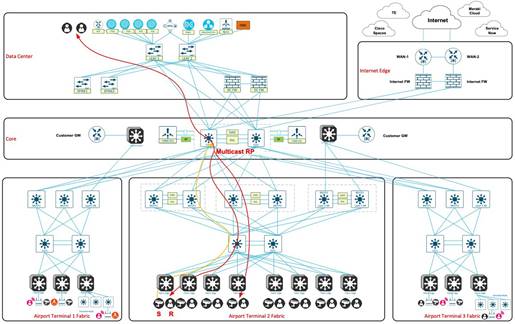
In the airport SDA network, a multicast Rendezvous Point (RP) is configured on a pair of Catalyst 9500 SVL core switches. The network utilizes native multicast, and during the testing phase in the transportation vertical, 8000 multicast entries is tested on the fabric devices. The multicast forwarding mechanism employed is ASM. This configuration ensures efficient handling and distribution of multicast traffic within the network architecture.
 |
Wireless Design in the Airport Network
The wireless network at the airport is characterized by high mobility and dynamism. It incorporates various modes, such as wireless Over the Top (OTT), which implies connectivity beyond the traditional network infrastructure. Additionally, SD-Access wireless, also known as fabric-enabled wireless, is implemented to enhance network flexibility and management. A mixed mode approach is also employed, where both fabric and nonfabric configurations coexist on the same wireless LAN controller, providing a versatile and adaptive wireless environment.
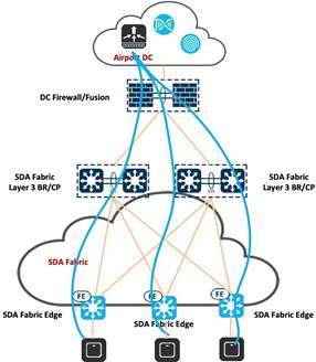
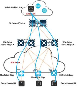
OTT Wireless in SDA Fabric Architecture
Wireless OTT operates seamlessly with the existing WLC, AP, and IOS/AireOS components, making it compatible with various software and hardware configurations. It is particularly useful in scenarios involving the support for SD-Access incompatible devices and serves as a migration step towards full SD-Access adoption. The deployment employs Control and Provisioning of Wireless Access Points (CAPWAP) for both the control plane and data plane functionalities and using the Cisco SD-Access fabric purely as a transport network. This approach is suitable when there are no immediate advantages of transitioning to SD-Access for wireless operations, or when a stepwise migration is preferred, allowing time for different operational teams to manage wired and wireless components independently. It caters to scenarios where customers prioritize migrating the wired infrastructure first, aligning with distinct operational cycles or when limitations such as older APs or software certification hinder an immediate transition to the fabric for wireless networks. With OTT-based wireless deployments, the control, management, and data plane traffic flow through the SD-Access fabric via a CAPWAP tunnel connecting APs and WLC.
 |
Cisco SDA Wireless
Airports can seamlessly integrate wireless functionality into SD-Access through two additional components: fabric wireless controllers and fabric mode APs. Cisco Wireless LAN Controllers, when configured as fabric wireless controllers, communicate with the fabric control plane, registering essential information such as Layer 2 client MAC addresses, SGT, and Layer 2 VNI. Fabric mode APs are associated with these controllers and configured with fabric-enabled service set identifiers (SSIDs).
In SD-Access wireless, the control plane is centralized, maintaining a CAPWAP tunnel between APs and WLC. The key distinction is that the data plane is distributed using VXLAN directly from the fabric-enabled APs. WLC and APs seamlessly integrate into the fabric, with APs connecting to the fabric overlay network as special clients.
Some notable benefits of SDA wireless include:
● Centralized wireless control plane.
● Leveraging existing innovative RF features.
● Optimized distributed data plane for enhanced performance and scalability.
● Seamless Layer 2 roaming across the campus.
● Simplified guest and mobility tunneling without the need for an anchor WLC.
● Policy simplification by breaking dependencies between policies and network constructs.
Segmentation is facilitated end-to-end in the fabric by following a hierarchical structure based on VNIs and SGTs, ensuring consistent application of segmentation policies for both wired and wireless users. For airport deployments, all SSIDs should be fabric-enabled, fabric-enabled APs should terminate VXLAN directly into the fabric edge, and the WLC should be physically located on the same site as APs.
Key considerations include using client MAC addresses as endpoint identifier (EID), WLC interaction with the host tracking DB for client MAC address registration, and the responsibility of the WLC in updating the host tracking DB with roaming information for wireless clients. These advantages can be realized at any airport with future-ready Wi-Fi 6 APs and a Cisco WLC, ensuring best-in-class wireless connectivity.
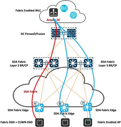
Mixed Mode Wireless (Fabric and Nonfabric on the same WLC)
Airports have the option to implement mixed mode setups, enabling the coexistence of both fabric and nonfabric wireless networks on a single WLC. This configuration facilitates the utilization of both SD-Access fabric wireless and OTT connections through the same WLC and AP. This approach can serve as a transitional step towards achieving a fully integrated SD-Access wireless infrastructure. Additionally, it accommodates the requirement for certain SSIDs to continue operating under the Cisco Unified Wireless Network OTT framework. Mixed mode deployment is applicable for both greenfield deployments and scenarios necessitating the concurrent operation of fabric and nonfabric wireless solutions.
 |
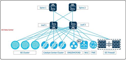
Airport Data Center with Cisco ACI
Cisco Application Centric Infrastructure (ACI) is an integrated and scalable architecture designed for comprehensive network management. It features centralized automation, policy-driven application profiles, and a fabric foundation that combines hardware, software, and ASIC innovations. ACI supports both physical and virtual networks, promoting rapid integration, customization, and visibility. The architecture fosters agility and reduced deployment time for IT by providing a common management framework for network, application, security, and virtualization teams. ACI is optimized for current and future application architectures, ensuring multitenancy, security, and telemetry for SLAs. It allows IT teams to offer cloud-based services with specific SLAs and performance requirements, and its open-programmable nature supports various data center management choices. Key characteristics include simplified automation, centralized management, mixed workload optimization, secure multitenancy, and openness for DevOps teams and ecosystem partner integration. ACI aims to provide comprehensive investment protection and lower overall total cost of ownership (TCO).
The Catalyst Center cluster, Cisco ISE cluster, DHCP server, NTP server, and CA server are connected to the ACI leaf switch within the airport data center.
 |
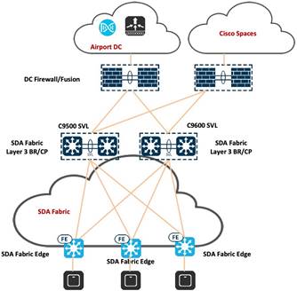
Cisco Spaces Captive Portal with Catalyst 9800 Wireless Controller
Cisco Spaces Captive Portal is a feature within the Cisco Spaces platform that allows organizations to create and manage captive portals for guest Wi-Fi access. Captive portals are web pages that users are redirected to when they attempt to connect to a Wi-Fi network. These portals often require users to log in or agree to terms of service before gaining access to the internet.
Using Cisco Spaces Captive Portal, organizations can create a secure and branded onboarding experience for guest users connecting to their Wi-Fi networks. This feature is particularly valuable in environments such as retail spaces, hotels, airports, and other public venues where providing Wi-Fi access to guests is common.
Key features of Cisco Spaces Captive Portal include:
● Customization
The ability to customize the appearance of the captive portal to align with the organization's branding. This can include adding logos, background images, and other visual elements.
● Authentication Methods
Support for various authentication methods, such as social media login (for example, Facebook, Google), email authentication, or custom registration forms. This allows organizations to choose the method that best suits their guest access policies.
● Access Policies
Configuration of access policies and restrictions for guest users, such as session duration, bandwidth limits, and other network-specific policies.
● Analytics and Insights
Integration with Cisco Spaces analytics to provide insights into user interactions with the captive portal. This can include data on the number of logins, user demographics, and other relevant metrics.
● User Experience Optimization
Features to enhance the overall user experience, such as easy navigation, clear instructions, and user-friendly interfaces.
● Integration with Cisco Spaces
● Seamless integration with the broader Cisco Spaces platform, which may include additional location-based services, analytics, and management capabilities.
 |
The following procedure shows how to integrate Cisco Spaces with Catalyst Center and Catalyst 9800 Series Wireless Controller.
Create SSIDs on Cisco Spaces
Step 1. In the Cisco Spaces dashboard, click Captive Portals.
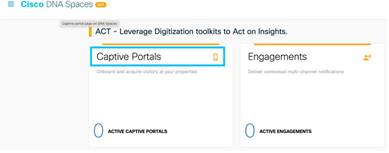 |
Step 2. In the Captive Portals window, click the menu icon in the top-left corner and choose SSIDs.
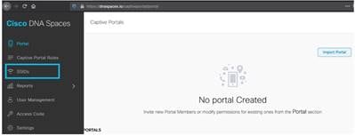
Step 3. Click Import/Configure SSID and choose Cisco Unified Wireless Network (CMX or WLC) as the wireless network type and enter the SSID name.
 |
For more information about configuring Cisco Spaces for guest access, refer to Configure DNA Spaces Captive Portal with Catalyst 9800 WLC.
ThousandEyes Integration with Catalyst Center
Cisco ThousandEyes is a network intelligence platform that provides visibility into the performance of applications and services across the internet. Organizations use ThousandEyes to monitor and analyze network performance, identify potential issues, and optimize the delivery of applications to end users.
There are two approaches for installing the ThousandEyes Enterprise Agent on Catalyst 9000 Series Switches. The first method involves manual configuration through the CLI, while the second option is an automated process facilitated by Catalyst Center. When deploying the ThousandEyes Enterprise Agent on a limited number of switches, using the CLI can be a viable initial step. However, for larger-scale deployments, relying on the CLI may become cumbersome and challenging to manage over time. In such scenarios, Catalyst Center proves to be the optimal solution, offering not only a streamlined installation process but also comprehensive management of the application lifecycle.
 |
The following procedure shows how to integrate ThousandEyes Enterprise Agents on Catalyst Center.
For more information on the configuration details, refer to ThousandEyes Enterprise Agent Deployment Guide on Catalyst 9300 and 9400 Switching Platforms.
Step 1. From the top-left corner, click the menu icon and choose Provision > Services > Application Hosting.
Step 2. Add the ThousandEyes application for switches.

Step 3. Verify that the application has been installed properly.

Step 4. Verify that the ThousandEyes Enterprise Agents are running on the fabric switches.
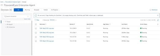 |
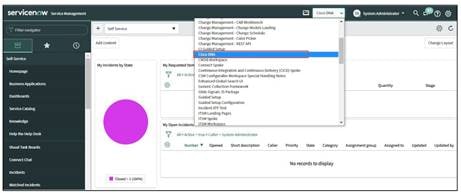
ServiceNow Integration with Catalyst Center
Catalyst Center supports the integration with ServiceNow.
The Catalyst Center application is installed within the ServiceNow instance and can perform various tasks by integrating with Catalyst Center Bundles. Catalyst Center Bundles are prebuilt solutions within Catalyst Center that enable integration between Catalyst Center and ServiceNow to execute various tasks.
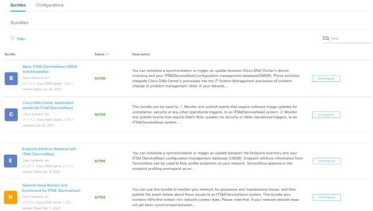
Catalyst Center Bundles are prebuilt solutions that enable integration between Catalyst Center capabilities and specific IT domains. The following Bundles can be configured and used:
● Basic ITSM (ServiceNow) CMDB Synchronization
Schedules one-way synchronization of Catalyst Center discovered devices into the ServiceNow Configuration Management Database (CMDB) using Catalyst Center inventory as a source of truth.
● Catalyst Center Automation Events for ITSM (ServiceNow)
Supports integration of Catalyst Center with ServiceNow for an automated way to create Change Request (CR) tickets in ServiceNow for network events performed on Catalyst Center like SWIM upgrades and adding or deleting devices from SDA fabric.
● Endpoint Attribute Retrieval with ITSM (ServiceNow)
Schedules one-way synchronization of endpoint assets from ServiceNow asset table to Catalyst Center AI Endpoint Analytics. This endpoint information can be used to profile the endpoints on Catalyst Center.
● Network Issue Monitor and Enrichment for ITSM (ServiceNow)
Facilitates to monitor a network for assurance and maintenance issues by retrieving subscribed events from Catalyst Center Assurance and publishing them to ServiceNow during the event’s occurrence.
An incident is created in ServiceNow for the event, which can be tracked until final resolution.
 |
 |
 |
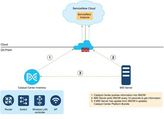 |
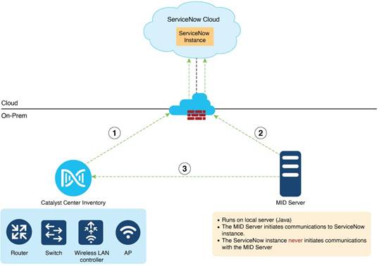
The workflow consists of the following components:
● Catalyst Center: On-premises Catalyst Center managing the network components (Switches/Routers/Wireless LAN controllers/APs)
● ServiceNow Instance: Enterprise customer’s ServiceNow account hosted on ServiceNow cloud.
● Management Instrumentation and Discovery Server (MID Server): Local server (Windows or Linux) to facilitate communication between ServiceNow and Catalyst Center. MID Server polls ServiceNow every 15 seconds and updates it to the Catalyst Center platform bundle.
For more information, refer to the Cisco Catalyst Center Administrator Guide.
Validated Solution Use Cases
The following sections describe some of the important use cases validated for Airport networks that serve as trusted templates. This empowers organizations to construct their IT infrastructure with certainty, knowing that these designs have undergone thorough testing and are tailored to effectively fulfill their unique business requirements.
Day-0 Operation Use Cases
Bring up a new terminal with wired devices in Catalyst Center:
● Provision a network through LAN automation.
● Discover devices and topologies.
● Provision configurations.
● Create a fabric.
● Add the device to the fabric.
Deploy wireless networks for a new terminal in Catalyst Center:
● Upload a floor map to a Catalyst Center site.
● Add new APs with Plug and Play, assign new APs to the new site location, and locate them on the floor map.
● Create and provision wireless profiles and policies on the new site.
● Integrate with Cisco Spaces. Monitor real-time device locations and client behavior.
Day-1 Operation Use Cases
Manage and provision wireless networks with Catalyst Center:
● Modify wireless settings and network profiles.
● Create new SSIDs and update existing SSIDs.
● Update profiles, tags, AP zones, and so on.
● Onboard new APs with Plug and Play.
● Replace or refresh APs through Catalyst Center workflows.
● Change AP locations and reprovision APs.
Manage and provision network security with Catalyst Center:
● Monitor threats and manage rogue rules and Advanced Wireless Intrusion Prevention System (aWIPS) profiles.
● Configure guest access Wi-Fi with traffic segmentation.
● Apply MAC Authentication Bypass (MAB) or Dot1x authentication for AP onboarding.
● Configure wired and wireless endpoint security policies, such as Dot1x authentication and a preshared key (PSK).
● Scan network devices and provide security advisories.
Network Management, Monitoring, and Troubleshooting Use Cases
Manage network inventory with Catalyst Center:
● Onboard devices through Plug and Play.
● Discover devices by IP address or Cisco Discovery Protocol (CDP).
● Replace broken devices.
● Run compliance checks.
● Move devices between locations.
● Manage device certificates.
● Manage password changes.
Manage device configurations with Catalyst Center:
● Use device templates to deploy new configurations.
● Track device configuration changes.
● Use Assurance audit logs to monitor any errors that occurred during configuration.
Manage device software and schedule upgrades with Catalyst Center:
● Upgrade network routers and switches, including SLV pairs and stack switches.
● Upgrade wireless devices, including wireless controller SSO pairs and C9800-CL.
● Schedule AP rolling upgrade.
● Generate software image management (SWIM) report.
Monitor network and device health, client endpoints, and network utilizations with Assurance:
● Monitor network device health and utilizations.
● Monitor system health for each location.
● Monitor network services, such as AAA and DHCP.
● Monitor wireless controllers and APs.
● Monitor the number of wired and wireless clients and details.
Troubleshoot network issues with Catalyst Center:
● Access devices and run CLI commands through SSH.
● Compare device configuration changes.
● Run a path trace and discover any link failures.
● Analyze the root cause of high CPU utilization.
● Check audit logs for troubleshooting applications or device public key infrastructure (PKI) certificates.
System and Network Robustness Use Cases
Verify system-level resiliency during the following events:
● Wireless controller SSO.
● Single AP failure.
Verify system-level resiliency during the following events:
● SVL border and control plane failover.
● SVL border and control plane link failure.
● Stack access switch member failure.
● Link failure between the distribution and fabric edge.
● Link failure between the distribution and fabric border and control plane node.
Verify system-level resiliency during the following events:
● Policy Service Node (PSN) failure.
● Policy Administration Node (PAN) failover.
● Cisco ISE PSN change.
● Cisco ISE upgrade.
Scale Matrix
The solution is verified with the scale numbers listed in the following table. For the software and hardware compliance, refer to the Cisco Catalyst Center Data Sheet.
| Attribute |
Airport SDA Scale Numbers |
| APs |
4,000 |
| Fabric edges |
500 |
| Wireless endpoints |
100,000 |
| Network profiles |
10 |
| Buildings and floors |
500 |
| SSIDs |
20 |
| Wireless controllers |
Two for wireless controller SSO HA pairs, two for an N+1 HA wireless controller, and one for a guest anchor |
| Wireless endpoints per AP |
20 wireless endpoints per AP |
| Layer 3 virtual networks |
16 |
| Layer 2 virtual networks |
800 |
| Guest clients |
80,000 |
| Airport, airline, and vendor clients |
20,000 |
Note: Catalyst Center on ESXi virtual appliance supports the same scale and performance as a 44-core physical appliance for small scale environment. For more information, refer to Cisco Catalyst Center on ESXi Deployment Guide.
Hardware and Software Specifications
The solution is validated with the hardware and software listed in this table. For a complete list of supported hardware and software, refer to the Cisco Catalyst Center Compatibility Matrix.
| Role |
Hardware platform |
Software version |
Software version |
| Catalyst Center |
DN3-HW-APL-XL |
2.3.7.9 |
2.3.7.10 |
| Catalyst Center |
DNA-SW-OVA |
2.3.7.9 |
2.3.7.10 |
| Identity Management, RADIUS Server |
SNS-3695-K9 |
Cisco ISE 3.3 Patch 4 |
Cisco ISE 3.4 Patch 3 |
| Cisco Wireless Controller |
C9800-80-K9, C9800-CL |
17.9.6, 17.12.5 |
17.12.5, 17.15.4d, 17.18.3 |
| Cisco SD-Access Fabric Edge |
C9200, C9300, C9400 |
17.9.6a, 17.12.5, 17.15.3 |
17.12.6, 17.15.4d, 17.18.3 |
| Fabric Border/Control Plane |
C9500-40x/C9606R |
17.9.6a, 17.12.5, 17.15.3 |
17.12.6, 17.15.4d, 17.18.3 |
| Cisco Firepower Threat Defense Security Appliances |
FPR9300, FPR4100 |
7.4.2 |
7.4.2 |
| Cisco Secure Firewall Management Center |
FMC Virtual |
7.4.2 |
7.4.2 |
| Cisco Industrial Ethernet 4000 Extended Node |
IE4000 |
15.2(8)E5 |
15.2(8)E7 |
| Cisco Spaces |
Cisco Spaces Connector |
3.1 |
3.2 |
| ThousandEyes |
Cloud Service |
4.4.4 |
5.1.0 |
● Catalyst Center on ESXi has limitations and restrictions. See the Cisco Catalyst Center on ESXi Release Notes.
● Unlike the Catalyst Center appliance platform, you cannot connect VMs to create three-node clusters. To achieve HA, you must use VMware vSphere. For more information, refer to Cisco Catalyst Center on ESXi Administrator Guide.
Technical References
● Cisco SD-Access Solution Design Guide (CVD)
● Cisco Catalyst Center Administrator Guide
● Support for Multiple Cisco Catalyst Center Clusters with a Single Cisco ISE System
● Cisco Catalyst Center Release Notes
● Cisco Catalyst Center Security Best Practices Guide
● Software Defined Access (SDA) Provisioning Best Practice Guide