Cisco Crosswork Hierarchical Controller 10.0 Installation Guide
Available Languages
Bias-Free Language
The documentation set for this product strives to use bias-free language. For the purposes of this documentation set, bias-free is defined as language that does not imply discrimination based on age, disability, gender, racial identity, ethnic identity, sexual orientation, socioeconomic status, and intersectionality. Exceptions may be present in the documentation due to language that is hardcoded in the user interfaces of the product software, language used based on RFP documentation, or language that is used by a referenced third-party product. Learn more about how Cisco is using Inclusive Language.
- US/Canada 800-553-2447
- Worldwide Support Phone Numbers
- All Tools
 Feedback
 Feedback
This document is an installation guide for Cisco Crosswork Hierarchical Controller.
The document explains:
● Cisco Crosswork Hierarchical Controller Prerequisites
● Install Cisco Crosswork Hierarchical Controller Platform
● Upgrade Cisco Crosswork Hierarchical Controller Platform
● Install Cisco Network Services Orchestrator Crosswork Hierarchical Controller Function Pack
Cisco Crosswork Hierarchical Controller Prerequisites
Cisco Crosswork Hierarchical Controller supports Standalone (SA) or supercluster deployment models.
For geo-redundancy, a supercluster may be deployed in a 1+1+1 scenario, which includes:
● active single-node (worker) cluster
● standby single-node (worker) cluster
● single witness (arbitrator) node
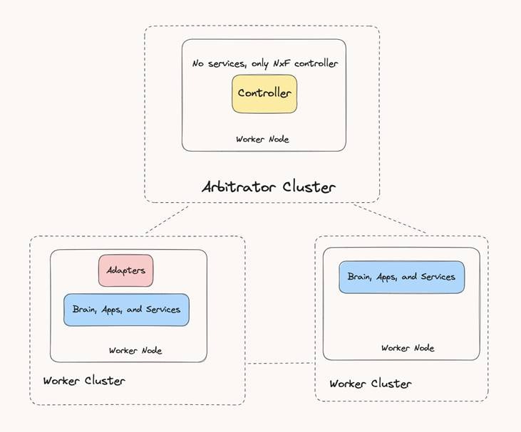
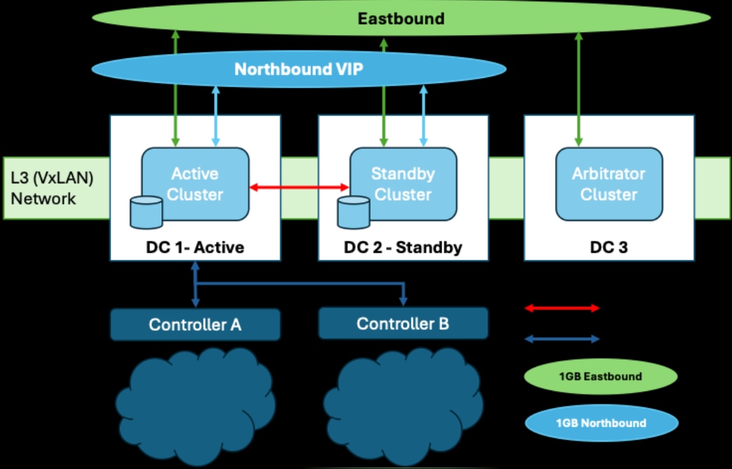
Cisco Crosswork Hierarchical Controller Supercluster Architecture
Cisco Crosswork Hierarchical Controller is released with a single VMWare OVA file distribution. OVA is a disk image deployed using vCenter on any ESXi host. This OVA packages together several components including a file descriptor (OVF) and virtual disk files containing a basic operating system and the Cisco Crosswork Hierarchical Controller installation files.
OVA can be deployed using vCenter on ESXi hosts supporting Standalone (SA) or supercluster deployment models.
● VMware vCenter Server 7.0 Update 3
● VMware ESXi 7.0 Update 3
Note: The system was tested with VMware ESXi version 7.0 Update 3. The system is expected to function as expected with other VMware ESXi 7.0 sub-versions as well. If you are using a sub-version other than VMware ESXi 7.0 Update 3 and you encounter any issues, contact your Cisco support representative.
This spec is for primary or standalone instances of Crosswork Hierarchical Controller.
| Hardware |
Requirement |
| CPU |
10 Cores |
| Memory |
96 GB |
| Multiple ESXi hosts (Control Plane) |
Minimum 1 Gbps required between hosts; up to 10 Gbps in scaled environments. |
| Storage |
500 GB SSD to 2 TB (Scale requirement) Note: This is without considering RAID configurations |
| HW Reservation |
100% for CPU and memory |
| NICs |
2 for standalone 3 for supercluster |
This spec is for the witness (or arbitrator) instance of Crosswork Hierarchical Controller.
| Hardware |
Requirement |
| CPU |
4 Cores |
| Memory |
32 GB |
| Storage |
200 GB SSD |
| HW Reservation |
100% for CPU and memory |
| NICs |
3 for supercluster |
This spec is for the witness (or arbitrator) instance of Crosswork Hierarchical Controller.
| Latency |
Requirement |
| Geo-redundancy (1+1+1) |
<100 milliseconds between clusters (1+1+1) for the Eastbound Network |
The client machine requirements are:
● Windows PC or MAC
● GPU
● Web browser with GPU hardware acceleration support
● Recommended
◦ Screen resolution 1920x1080
◦ Google Chrome Web browser version 75 or later is recommended
Note: GP U is mandatory to properly get all the benefits of the network 3D map.
The table that follows lists the default port assignments. The ports can be customized as necessary to meet your network requirements.
| User |
Role |
Description |
| Inbound |
TCP 22 |
SSH remote management |
| TCP 8443 |
HTTPS for UI access |
|
| Outbound |
TCP 22 |
NETCONF to routers |
| TCP 389 |
LDAP if using Active Directory |
|
| TCP 636 |
LDAPS if using Active Directory |
|
| Customer Specific |
HTTP for access to an SDN controller |
|
| Customer Specific |
HTTPS for access to an SDN controller |
|
| TCP 3082, 3083, 2361, 6251 |
TL1 to optical devices |
|
| syslog |
Customer specific |
TCP/UDP |
| Control Plane Ports (Internal network between cluster nodes, not exposed)
|
Kubernetes |
TCP 443 |
| Kubernetes |
TCP 6443 |
|
| Kubernetes |
TCP 10250 |
|
| etcd |
TCP 2379 |
|
| etcd |
TCP 2380 |
|
| VXLAN |
UDP 8472 |
|
| Ping between nodes (optional) |
ICMP |
The storage volume required for Crosswork Hierarchical Controller production depends on the amount of storage needed for performance counters and for daily DB backups.
The performance monitoring storage is calculated based on the number of client ports and the amount of time the counters are stored. The ballpark figure is 700 MB for 1000 ports.
The detailed formula to calculate the storage is:
<uncompressed data>=<number of ports>*<samples per day>*<number of days>*60
Storage = (<uncompressed data>*0.1)+<daily backup size>*<number of days>*<number of months>
Taking the following assumptions into account:
● Samples – samples per day
● Sample size per port – 60 bytes
● Days – number of days the PM data is stored
● Compression ratio – data is compressed in DB, at a ratio of ~10%
● Daily backup – ~60 MB per day
● Number of backup days – 14 days
● Number of backup months – default is 12 months
Crosswork Hierarchical Controller certified scaling.
| Component |
Maximum Certified |
| Total number of devices |
10,000 |
| Total number of L2 links |
39,127 |
| Total number of L3 links |
48,522 |
| Total physical interfaces |
230,014 |
| Total logical interfaces |
320,061 |
| Total LAG interfaces |
169,898 |
| Total L2 VPN services |
51,038 |
| Total L3 VPN services |
49,931 |
Important: The scale numbers above were certified during integration with Cisco Crosswork Network Controller and validated through the Crosswork Hierarchical Controller Network Inventory and SHQL applications. Support for other controllers or Crosswork Hierarchical Controller applications will be provided on a best-effort basis.
Install Crosswork Hierarchical Controller Platform
Northbound and Eastbound Networks Requirements
The following list contains the pre-requisites of Cisco Crosswork Hierarchical Controller installation.
Before installing Cisco Crosswork Hierarchical Controller:
● Install the ESXi host on servers with vSphere to support creating VMs.
● Create three networks and assign each to a separate zone:
◦ The northbound network is used for communication between the client and a cluster.
◦ The eastbound network is used for communication between the clusters within the supercluster.
◦ The control plane network helps in the communication between the deployed VMs within a cluster.
Note: Although the control plane network is not in use for the standalone or supercluster 1+1+1 configuration, it should still be created.
To create the networks:
1. From the vSphere client, select the Datacenter where you want to add the ESXi host.
2. After adding the ESXi host, create the networks before deploying the standalone or supercluster:
◦ Standalone: Three IPs (v4). Assign a VIP for the northbound interface (for standalone, the VIP and northbound IP are the same), another real IP for the control plane, and a dummy IP for the eastbound interface.
◦ Supercluster: Seven IPs (v4). Assign three IPs each for the northbound and eastbound networks for the active single-node cluster, standby single-node cluster, and single witness (arbitrator) node, and a VIP. The VIP is the IP that exposes the active single-node cluster to the user.
Cisco Crosswork Hierarchical Controller Supercluster Requirements
BGP Installation Requirements
Supercluster:
● BGP is used for traffic routing to the virtual IP from the various locations.
● Configure the BGP password (<BGP_session_password>) on the peer site gateway BGP router. Without this, the BGP session will not start. This is used for Region 1 and 2.
SSH to Crosswork Hierarchical Controller requires a public and private SSH key to be generated upfront before OVA deployment:
● Public SSH key is passed as a parameter during OVA deployment
● Private key is required to execute the remote SSH login
● SSH key must use the ed25519 encryption algorithm
To generate the keys:
1. Execute the ssh-keygen command:
# ssh-keygen -t ed25519 -f <PATH>/<keyname>
This generates the public and private keys:
◦ <keyname>.pub: Public key
◦ <keyname>: Private key
2. Remove the comment from the public key before using it during the OVA deployment.
Install Standalone Crosswork Hierarchical Controller
When you deploy the OVA template it installs the Crosswork Hierarchical Controller platform and the various Crosswork Hierarchical Controller applications.
Note: It is suggested that you keep track of all settings in a spreadsheet before proceeding.
To install Crosswork Hierarchical Controller:
1. Right-click on the ESXi host in the vCenter vSphere Client screen, and then click Deploy OVF Template.
2. On the Select an OVF template page, specify the location of the source OVA template:
◦ URL: A URL to an OVA template located online.
◦ Local file: A location with the OVA template.
3. Click Next.
4. On the Select a name and folder page, specify a unique name for the VM Instance. The Virtual machine name must be a valid DNS name:
◦ contain no more than 253 characters
◦ contain only lowercase alphanumeric characters, '-' or '.'
◦ start with an alphanumeric character
◦ end with an alphanumeric character
5. From the list of options select the location of the VM to be used.
6. Click Next.
7. On the Select a compute resource page, select the destination compute resource on which you want to deploy the VM.
Note: While selecting the compute resource the compatibility check proceeds until it completes successfully.
8. Click Next.
9. On the Review details page, verify the template details.
10. Click Next.
11. On the Select storage page, set the Select virtual disk format based on SSD.
12. Leave the VM Storage Policy set to Datastore Default.
13. Select the storage.
14. Click Next.
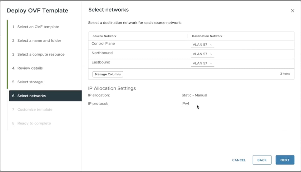
15. In the Select networks page, set the destination networks:
◦ Control Plane: The control plane network.
◦ Northbound: The VM network used for the VIP address for RESTCONF or UI access.
◦ Eastbound: The VM network used for communication within the cluster.
16. Click Next.
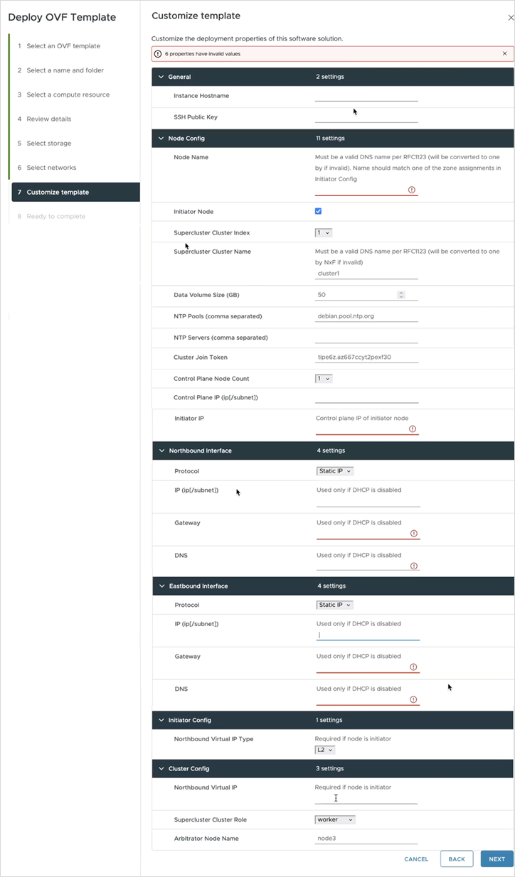
17. In the Customize template page, set the values as follows:
| Key |
Value |
| General |
|
| Instance Hostname |
The instance hostname. This is the same as used in 2. Select a name and folder page and must be a valid DNS name. |
| SSH Public Key |
The ssh public key generated by the customer’s admin. For example: ssh-keygen -t ed25519 -f ~/.ssh/... |
| Node Config |
|
| Node Name |
The standalone node name. This must be a valid DNS name: · contain no more than 253 characters · contain only lowercase alphanumeric characters, '-' or '.' · start with an alphanumeric character · end with an alphanumeric character This must exist in the zone config, that is, the name must match one of the zone assignments in the Initiator Config. |
| Initiator Node |
This is checked by default. Leave as is. The standalone node will be the initiator. |
| Supercluster Cluster Index |
The supercluster cluster index. Leave as is. |
| Supercluster Cluster Name |
The supercluster cluster name. Must be a valid DNS name per RFC1123. Leave as is. |
| Data Volume Size (GB) |
The data storage limit set for the host. See Requirements. Must be at least 500. |
| NTP Pools (comma separated) |
(Optional) A comma-separated list of the NTP pools. |
| NTP Servers (comma separated) |
(Optional) A comma-separated list of the NTP servers. |
| Cluster Join Token |
This is filled in automatically. Leave as is. |
| Control Plane Node Count |
Select 1. |
| Control Plane IP (ip[/subnet]) |
The private IP for the node. For standalone, this must be a local valid IP in the customer’s hypervisor. |
| Initiator IP |
For standalone, use the same IP set as the control plane IP. |
| Northbound Interface |
|
| Protocol |
Select Static IP or DHCP from the menu. |
| IP(ip[/subnet]) - if not using DHCP |
The public IP and subnet mask (in CIDR notation, that is, X.X.X.X/nn) for the instance northbound network if not using DHCP. Note: The subnet mask is mandatory. |
| Gateway - if not using DHCP |
The gateway IP for the instance northbound network if not using DHCP. |
| DNS |
The DNS server IP. |
| Eastbound Interface |
|
| Protocol |
Select Static IP or DHCP from the menu. |
| IP(ip[/subnet]) - if not using DHCP |
The public IP and subnet mask (in CIDR notation, that is, X.X.X.X/nn) for the instance eastbound network if not using DHCP. For standalone this can be the same as the control plane IP. Note: The subnet mask is mandatory. |
| Gateway - if not using DHCP |
The gateway IP for the instance eastbound network if not using DHCP. |
| DNS |
The DNS server IP. |
| Initiator Config |
Complete the entry for the standalone node |
| Northbound Virtual IP Type |
The northbound IP type. Set this to L3. Required as the standalone node is the initiator. |
| Cluster Config |
Complete the entry for the standalone node |
| Northbound Virtual IP |
The IP of the standalone instance used for RESTCONF or UI access. Required as the standalone node is the initiator. This is the same as the IP(ip[/subnet]) - if not using DHCP. |
| Supercluster Cluster Role |
Leave as is (worker). |
| Arbitrator Node Name |
Leave as is. |
18. Click Next.
19. In the Ready to complete page, check the selections.
20. Copy and save the properties as a backup.
21. Click Finish.
22. Right-click on the VM in the vSphere Client screen and select Edit Settings.
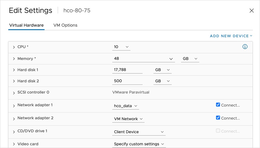
23. For CPU, select 10 and for Memory select 96.
24. Edit the CPU Resources and set the Reservation to 100%.
25. Edit the Memory Resources and set the Reservation to 100%.
26. Click OK.
27. Power on the VM. It may take a few minutes to get SSH access.
28. Try connecting to the VM. For this, use the private key associated with the public key used earlier during customizing public key options. Login to the VM:
# ssh -i <private-key_file> nxf@<hco_management_ip>
◦ If you are prompted for a password, there is probably a problem with the key.
◦ If the command timeouts, check the IP setting.
29. Run the following command to check the system status:
sedo system status
30. Change the default password and access string of the admin user:
sedo security user set --access role/admin -–password admin
Note: You will be prompted to provide a new password.
31. You can use sedo to configure the local users. For more information, see the Crosswork Hierarchical Controller Administration Guide.
32. Browse to the Crosswork Hierarchical Controller application using the Northbound Virtual IP and port 8443:
https://[Northbound Virtual IP]:8443/
Install Supercluster 1+1+1 Crosswork Hierarchical Controller
This procedure describes deploying a geo-redundancy supercluster in a 1+1+1 scenario, which includes:
● active single-node cluster
● standby single-node cluster
● single witness (arbitrator) node
Prerequisites: BGP is used for traffic routing to the virtual IP from the various locations.
Note: Clusters cannot be added/removed or change roles after the clusters join the supercluster.
To install Crosswork Hierarchical Controller:
1. Right-click on the ESXi host in the vSphere Client screen, and then click Deploy OVF Template.
2. On the Select an OVF template page, specify the location of the source OVA template:
◦ URL: A URL to an OVA template located online.
◦ Local file: A location with the OVA template.
3. Click Next.
4. On the Select a name and folder page, specify a unique name for the VM Instance. The Virtual machine name must be a valid DNS name:
◦ contain no more than 253 characters
◦ contain only lowercase alphanumeric characters, '-' or '.'
◦ start with an alphanumeric character
◦ end with an alphanumeric character
5. From the list of options select the location of the VM to be used.
6. Click Next.
7. On the Select a compute resource page, select the destination compute resource on which you want to deploy the VM.
Note: While selecting the compute resource the compatibility check proceeds until it completes successfully.
8. Click Next.
9. On the Review details page, verify the template details.
10. Click Next.
11. On the Select storage page, set the Select virtual disk format based on SSD.
12. Leave the VM Storage Policy set to Datastore Default.
13. Select the storage.
14. Click Next.
15. In the Select networks page, set the destination networks:
◦ Control Plane: The control plane network. This may be the same for the active single-node cluster, standby single-node cluster, and single witness (arbitrator) node. This is not in use for the 1+1+1 configuration.
◦ Northbound: The VM network used for the VIP address for RESTCONF or UI access. This is different for the active single-node cluster, standby single-node cluster, and single witness (arbitrator) node.
◦ Eastbound: The VM network used for communication within the cluster. This is different for the active single-node cluster, standby single-node cluster, and single witness (arbitrator) node.
16. Click Next.
17. In the Customize template page, set the values as follows:
| Key |
Value |
| General |
|
| Instance Hostname |
The instance hostname. This is the same as used in 2. Select a name and folder page and must be a valid DNS name. |
| SSH Public Key |
The ssh public key generated by the customer’s admin. For example: ssh-keygen -t ed25519 -f ~/.ssh/... |
| Node Config |
|
| Node Name |
The node name. This must be a valid DNS name: · contain no more than 253 characters · contain only lowercase alphanumeric characters, '-' or '.' · start with an alphanumeric character · end with an alphanumeric character This must exist in the zone config, that is, the name must match one of the zone assignments in the Initiator Config. |
| Initiator Node |
This is checked by default. · Leave checked. |
| Supercluster Cluster Index |
The supercluster cluster index. Set to 1 (active cluster), 2 (standby cluster), or 3 (arbitrator). |
| Supercluster Cluster Name |
The cluster name. Must be a valid DNS name per RFC1123. This is different for the active single-node cluster, standby single-node cluster, and single witness (arbitrator) node. |
| Data Volume Size (GB) |
The data storage limit set for the host. See Requirements. Must be at least 500. |
| NTP Pools (comma separated) |
(Optional) A comma-separated list of the NTP pools. |
| NTP Servers (comma separated) |
(Optional) A comma-separated list of the NTP servers. |
| Cluster Join Token |
This is filled in automatically. Leave as is. |
| Control Plane Node Count |
Select 1 for all nodes (for supercluster 1+1+1) |
| Control Plane IP (ip[/subnet]) |
The private IP for the node. Not in use externally for supercluster 1+1+1. Can be a dummy IP. |
| Initiator IP |
The same IP as the control plane IP. |
| Northbound Interface |
|
| Protocol |
Select Static IP or DHCP from the menu. |
| IP(ip[/subnet]) - if not using DHCP |
The public IP and subnet mask (in CIDR notation, that is, X.X.X.X/nn) for the instance northbound network if not using DHCP. |
| Gateway - if not using DHCP |
The gateway IP for the instance northbound network if not using DHCP. |
| DNS |
The DNS server IP. |
| Eastbound Interface |
|
| Protocol |
Select Static IP or DHCP from the menu. |
| IP(ip[/subnet]) - if not using DHCP |
The public IP and subnet mask (in CIDR notation, that is, X.X.X.X/nn) for the instance eastbound network if not using DHCP. For standalone this can be the same as the control plane IP. Note: The subnet mask is mandatory. |
| Gateway - if not using DHCP |
The gateway IP for the instance eastbound network if not using DHCP. |
| DNS |
The DNS server IP. |
| Initiator Config |
|
| Northbound Virtual IP Type |
The northbound IP type. Set this to L3. |
| Cluster Config |
|
| Northbound Virtual IP |
The IP used for RESTCONF or UI access. This is the same for the active single-node cluster, standby single-node cluster, and single witness (arbitrator) node. |
| Supercluster Cluster Role |
Set to worker (active cluster), worker (standby cluster), or arbitrator (arbitrator). |
| Arbitrator Node Name |
Leave the default value. Not in use for the 1+1+1 configuration. |
18. Click Next.
19. In the Ready to complete page, check the selections.
20. Copy and save the properties as a backup.
21. Click Finish.
22. Right-click on the VM in the vSphere Client screen and select Edit Settings.
23. For CPU, select 10 and for Memory select 96.
24. Edit the CPU Resources and set the Reservation to 100%.
25. Edit the Memory Resources and set the Reservation to 100%.
26. Click OK.
27. Power on the VM. It may take a few minutes to get SSH access.
28. Try connecting to the VM. For this, use the private key associated with the public key used earlier during customizing public key options. Login to the VM:
# ssh -i <private-key_file> nxf@<hco_management_ip>
◦ If you are prompted for a password, there is probably a problem with the key.
◦ If the command timeouts, check the IP setting.
29. Run the following commands to get the supercluster routing up and running:
Region 1:
sedo ha bgp init <region1_node_name> <region1_northbound_ip> <BGP_AS_1>
sedo ha bgp router add <region1_node_name> <region1_northbound_gateway> <BGP_AS> <BGP_session_password>
Region 2:
sedo ha bgp init <region2_node_name> <region2_northbound_ip> <BGP_AS_2>
sedo ha bgp router add <region2_node_name> <region2_northbound_gateway> <BGP_AS> <BGP_session_password>
In both regions:
sedo ha bgp router list <region{n}_node_name>
30. Run the following command on each node and record the CLUSTER_ID:
sudo sedo supercluster status
31. On the Region 1 node, run the following command to generate a sudo command to run on the Region 2 node:
Region 1 (local) > Region 2 (remote):
sudo sedo supercluster wait-for -b <region1_node_eastboundIP>:10443 <region2_node_CLUSTER_ID>
32. On the Region 2 node, run the generated command.
33. On the Region 1 node, run the following command to generate a sudo command to run on the Region 3 node:
Region 1 (local) > Region 3 (remote):
sudo sedo supercluster wait-for -b <region1_node_eastboundIP>:10443 <region3_node_CLUSTER_ID>
34. On the Region 3 node, run the generated command.
35. On the Region2 node, run the following command to generate a sudo command to run on the Region 3 node:
Region 2 (local) > Region 3 (remote):
sudo sedo supercluster wait-for -b <region2_node_eastboundIP>:10443 <region3_node_CLUSTER_ID>
36. On the Region 3 node, run the generated command.
37. Run the following command on each node to view the peers:
sudo sedo supercluster status
38. Run the following command to check the supercluster connectivity:
sudo sedo supercluster connectivity
39. In region 1, run the following command to start the supercluster (this may take a few minutes):
sudo sedo supercluster start
40. Once connectivity check succeeds, run the following command to check the supercluster status (started):
sudo sedo supercluster status
41. Run:
sedo ha bgp show
42. Change the default password and access string of the admin user:
sedo security user set --access role/admin -–password admin
Note: You will be prompted to provide a new password.
43. You can use sedo to configure the local users. For more information, see the Crosswork Hierarchical Controller Administration Guide.
44. Browse to the Crosswork Hierarchical Controller application using the Northbound Virtual IP and port 8443:
https://[Northbound Virtual IP]:8443/
View Installed Crosswork Hierarchical Controller Applications
To view the installed Crosswork Hierarchical Controller applications:
1. After the installation is complete, ssh to the server.
2. Run the following command to see which applications are installed:
sedo hco apps list
The output displays the installed applications with their name and version.
Add Network Adapters and Discover Network Devices
For instructions on how to add network adapters and discover network devices, refer to the Cisco Crosswork Hierarchical Controller Administration Guide.
Upgrade Cisco Crosswork Hierarchical Controller
This topic describes how to upgrade Crosswork Hierarchical Controller.
Note: To upgrade from Crosswork Hierarchical Controller version 7.1 to version 10 is a three-step process:
1. Upgrade from version 7.1 to version 8.0. Refer to the Crosswork Hierarchical Controller Installation Guide version 8.0.
2. Upgrade from version 8.0 to version 9.0. Refer to the Crosswork Hierarchical Controller Installation Guide version 9.0.
3. Upgrade from version 9.0 to version 10.0
Upgrade Cisco Crosswork Hierarchical Controller 9.0 to 10.0
Upgrading Crosswork Hierarchical Controller version 9.0 to version 10.0, requires you to copy and upload the system pack to one of the nodes, pull It to the other instances, and then apply the upgrade on all nodes.
Note: Also download the adapter service packs. These will be required after the upgrade, and before you re-enable the adapters. The installation command MUST use the adapter names that are in use prior to upgrading, so record the names that appear in Device Manager.
To upgrade Crosswork Hierarchical Controller 9.0 to 10.0:
1. Make a full backup of the system.
2. Disable all the adapters. For each adapter:
a. In the applications bar in Crosswork Hierarchical Controller, select Device Manager > Adapters.
b. Select the required adapter in the Adapters list on the left.
c. Select the General tab.
d. Deselect the Enabled checkbox.
e. Click Save.
3. Disable each of the adapter services, for example, cisco-cnc-adpt:
sedo service disable <adapter_service_name>
4. Check that the adapter services are disabled:
sedo system status
5. Copy the system pack provided to one of the instances (e.g. node1).
6. Upload the system pack (from the node it was copied to, e.g. node1):
sudo sedo system upgrade upload <system-pack-name>
7. List the available upgrades:
sudo sedo system upgrade list
8. Pull the system pack on all other instances (there is no need to pull it to the instance on which it was uploaded):
sudo sedo system upgrade pull <system-pack-name>
9. Apply the upgrade (on all nodes):
sudo sedo system upgrade apply
Note: Wait for apply to be completed on all nodes before proceeding to the next step.
10. Reboot to complete (all nodes):
sudo reboot
11. Check:
sedo version, sedo hco version, sedo nso version
12. Download the adapter service packs.
13. Install the adapter service packs. The installation command MUST use the name that was in use prior to upgrading (if this is not the default adapter name, that is, if the DYNAMIC_APP_GUID param was used in the original installation to modify the name, install the new service pack with DYNAMIC_APP_GUID=[adapter name as it was displayed in Device Manager on v9].
14. Wait until the adapter pods are re-created using the newly installed service pack, and then validate that the adapter pods are restarted:
sedo system status command
15. Re-enable the adapters in Device Manager.
The NSO configuration is not persistent after upgrading to Crosswork Hierarchical Controller v10. For NSO, complete the following procedure while upgrading:
1. Create a backup of NSO using the command on the source version:
sedo nso backup create
Verify that a new backup was created and exported.
For example: ncs-6.1.6@2024-12-12T10:43:52.backup.gz
2. Upgrade Crosswork Hierarchical Controller to v10.
3. Before restoring NSO, modify the backup file name to match the current NSO version. For example:
mv ncs-6.1.6@2024-12-12T10:43:52.backup.gz ncs-6.1.11.2@2024-12-11T11_34_54.backup.gz
Note: Pay extra special attention to the text in bold.
4. Copy the renamed file to the pod using the command:
kubectl cp ncs-6.1.11.2@2024-12-11T11_34_54.backup.gz hco/nso-manager-srv-0:/nso/run/backups/
5. Restore NSO using the command:
sedo nso backup restore ncs-6.1.11.2@2024-12-11T11_34_54.backup.gz
6. Verify that NSO was restored successfully (using sedo logs) and wait for NSO to reload.
7. For devices, login to the NSO pod and create the authgroup.
Install a Cisco Network Services Orchestrator Crosswork Hierarchical Controller Function Pack
NSO Engine Embedded Inside Crosswork Hierarchical Controller
NSO runs as an Crosswork Hierarchical Controller micro-service, alongside the Crosswork Hierarchical Controller applications and adapters.
This exposes the NSO NBI from Crosswork Hierarchical Controller and the NSO UI as an Crosswork Hierarchical Controller application (which will mostly be used for configuration of Function Packs/NEDs).
Note: Crosswork Hierarchical Controller HA and embedded NSO integrate seamlessly. The NSO database exists on both the Crosswork Hierarchical Controller Active and Standby nodes, and the database is synchronized continuously. If the Crosswork Hierarchical Controller Active node fails, and the Standby node takes over and becomes the Active node, NSO is updated automatically and switches nodes too.
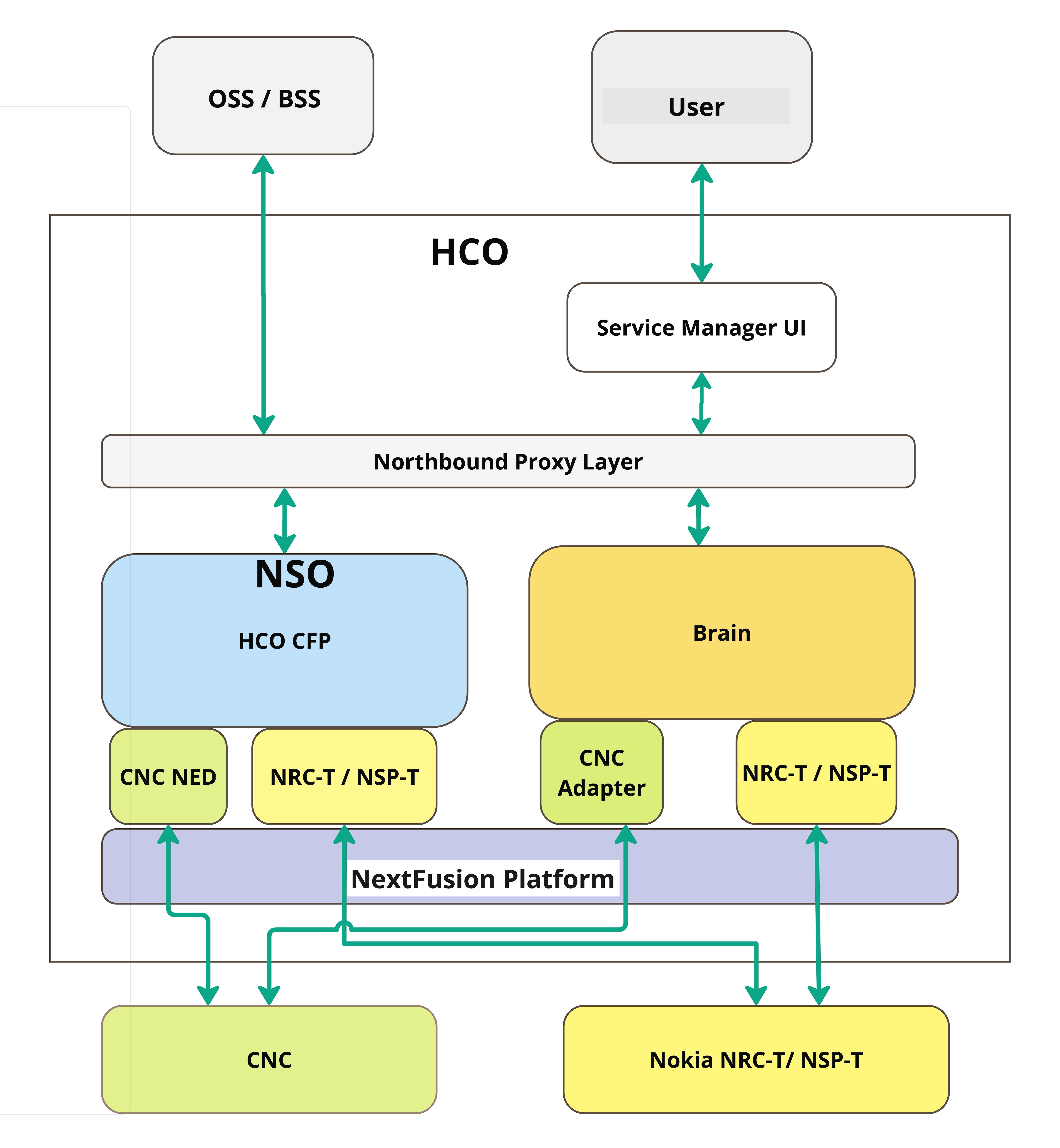
Network Services Orchestrator (NSO)
The Crosswork Hierarchical Controller Function Pack integrates Cisco NSO with a controller to deploy services on the controller. This integration is with either a Nokia Service Provider (NSP) controller or a Cisco Crosswork Network Controller (CNC). The NEDs are installed as part of the Function Pack installation.
For full details on installing and using the Network Services Orchestrator (NSO) Crosswork Hierarchical Controller Function Pack, see the:
● Cisco NSO Crosswork Hierarchical Controller - Function Pack Installation Guide
● Cisco NSO Crosswork Hierarchical Controller - Function Pack User Guide.
For details on Function Pack versions, contact your Cisco Representative.
For full details on installing and using the Cisco NSO Routed Optical Networking Core Function Pack, see the:
● Cisco NSO Routed Optical Networking Core Function Pack Installation Guide
● Cisco NSO Routed Optical Networking Core Function Pack User Guide
Install NSO Function Pack in Crosswork Hierarchical Controller Embedded Instance
The embedded NSO instance is a fully functional standalone container installation of NSO. The installation procedure is the same as the standard installation with one difference: the file system of NSO is not readily available on the host server.
To load the new function pack, the administrator must copy the function pack files onto the NSO pod, and then log into the pod shell and place the files in the correct directories. Once the files are on the NSO pod, follow the instructions in the Function Pack Installation Guide.
To install NSO Function Pack in Crosswork Hierarchical Controller Embedded Instance:
1. Connect to the Crosswork Hierarchical Controller host server via SSH.
2. Download the NSO function pack.
3. Copy the NSO function pack into the NSO pod:
kubectl cp [function-pack-file] <zone-a/zone-b>/nso-manager-srv-0:/usr/app
4. Log into the pod shell:
sedo shell <zone-a/zone-b>/nso-manager-srv
cd /usr/app/nso-temp
5. Continue with function pack extraction and installation as specified in the Function Pack Installation Guide.
Considerations for a High Availability (HA) Deployment
HA in NSO needs to be disabled for installing and updating function packs.
1. On both the active and standby nodes, in the NSO CLI execute:
admin@ncs> request high-availability disable
2. On both the active and standby nodes, install the function pack.
3. Restart the NSO pods to reactivate HA protection:
sudo kubectl --kubeconfig /etc/kubernetes/admin.conf -n zone-a scale statefulset nso-manager-srv --replicas=0
sudo kubectl --kubeconfig /etc/kubernetes/admin.conf -n zone-b scale statefulset nso-manager-srv --replicas=0
sudo kubectl --kubeconfig /etc/kubernetes/admin.conf -n zone-a scale statefulset nso-manager-srv --replicas=1
sudo kubectl --kubeconfig /etc/kubernetes/admin.conf -n zone-b scale statefulset nso-manager-srv --replicas=1
Example of How to Install the RON Function Pack
This describes an example of how to install a RON function pack on the NSO pod. This example refers to a version previously used. For the complete and most updated procedures, you must refer to the related Function Pack Installation Guide.
1. Copy the function pack file into the pod:
kubectl cp nso-6.1-ron-2.1.1.tar.gz zone-a/nso-manager-srv-0:/usr/app
2. Move into the NSO pod:
sedo shell zone-a/nso-manager-srv
cd /usr/app/nso-temp
3. Untar the function pack tar.gz file:
tar xvzf nso-6.1-ron-2.1.1.tar.gz
cd nso-6.1-ron-2.1.1/
4. Copy the function pack packages to the rundir:
cp ron/core-fp-packages/*.tar.gz $NCS_RUN_DIR/packages/
5. Initiate NSO CLI command from the specified path for loading packages:
cd $NCS_RUN_DIR/packages/
ncs_cli -u admin
6. Load the packages:
request packages reload
7. Verify that the function pack has successfully loaded:
show packages package package-version | select build-info ncs version | select build-info file | select build-info package sha1 | select oper-status error-info | select oper-status up | tab
8. Set SSH algorithms public-key:
configure
set devices global-settings ssh-algorithms public-key [ ssh-ed25519 ecdsa-sha2-nistp256 ecdsa-sha2-nistp384 ecdsa-sha2-nistp521 rsa-sha2-512 rsa-sha2-256 ssh-rsa ]
commit
9. Initiate NSO CLI command from the specified path to load merge XMLs:
cd /nso/run/packages/nso-6.1-ron-2.1.1/ron/bootstrap-data
ncs_cli -u admin
10. Load bootstrap data according to the function pack installation guide:
configure
unhide debug
unhide ron
load merge commit-queue-settings.xml
commit
...
<repeat for all files in installation guide>
...
load merge RON-status-codes.xml
commit
The device-type and ned-id depend on the actual device you want to connect, as well as the NED version installed on NSO. Update the commands below accordingly.
To add a device:
1. Add credentials:
set devices authgroups group <credential_name> default-map remote-name <username> remote-password <password>
commit
2. Add device:
set devices device <device_name> address <IP> authgroup <device_authgroup_name> device-type cli ned-id <cisco-iosxr-cli-7.49>
set devices device <device_name> state admin-state unlocked
commit
request devices device <device_name> ssh fetch-host-key
request devices device <device_name> connect
request devices device <device_name> sync-from