Configure and validate radio channel and bandwidth

4900-4990 MHz frequency support for US and Canada with license enforcement

From UIW Release 17.16.1, the Cisco Catalyst IW9167E, IW9165D, and IW9165E APs introduces additional support 4.9 GHz frequency band in URWB mode for Canada (-A) and -B (United States) domains.

When operating in the 4.9 GHz frequency bands for -A and -B domains, devices use 10 MHz and 20 MHz channel bandwidths with 5 MHz channel spacing.

The 4.9 GHz frequency bands are available on both the radio slot 1 and slot 2 and is disabled by default.


Note


The -A and -B domains do not support IEEE 802.11ax rates when operating in 4.9 GHz.


Table 1. 4.9 GHz Frequency Bands Supported for the 10 MHz and 20 MHz Channel Bandwidth

Channel

Channel bandwidth (10 MHz)

Channel bandwidth (20 MHz)

11

4945

NA

19

4985

NA

20

4950

4950

21

4955

4955

22

4960

4960

23

4965

4965

24

4970

4970

25

4975

4975

26

4980

4980

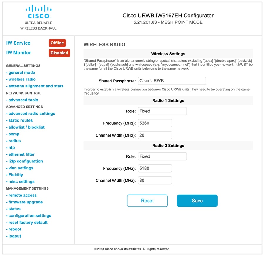
Enable 4900-4990 MHz frequency bands

The IW Service sends the 4.9 GHz frequency band enablement configuration to the AP.

Use this task to enable the 4.9 GHz frequency bands on the AP.

Procedure


Step 1

Configure the 4.9 GHz frequency band enablement using IW Service Cloud-Managed or offline deployment mode.

For more information on how to configure the 4.9 GHz band enablement from IW Service, see the Introduction to Industrial Wireless.

Step 2

Enable or disable 802.11an/ac rates.

Use the command configure dot11Radio <radio> 4.9G high-throughput to enable or disable 802.11 an/ac rates.

Device#configure dot11Radio <radio> 4.9G high-throughput

  disable  disable high-throughput and use 802.11a
  enable   enable hight-throughput (802.11ac/n) in low mode 

Example:

  • Device#configure dot11Radio 1 4.9G high-throughput enable
  • Device#configure dot11Radio 1 4.9G high-throughput disable

Note

 
  • If disabled, the radio interface operates only at 802.11a rates, unlocking high-power profile.

  • If enabled, the radios are allowed to operate at higher rates, limiting the power profile.


5855-5935 MHz frequency support

The Intelligent Transport Systems (ITS) frequency band refers to the radio spectrum allocated in Europe to support ITS.

This band spans 5875–5935 MHz and is subdivided for specific applications:

  • 5875–5915 MHz is designated for Road ITS applications

  • 5915–5935 MHz is allocated for Urban Rail Systems, such as automatic train control systems Communications-Based Train Control (CBTC)

The use of this band is subjected to license approval from the relevant national regulatory authority.

From UIW Release 17.18.1, the Cisco Catalyst IW9167E, IW9165D, and IW9165E APs support the ITS frequency band within the European regulatory domain (-E PID).

New power table for the -E domain

A new power table is introduced for the -E domain. This allows for various frequencies from 5860 MHz to 5930 MHz at 10 MHz intervals. See the table below for channel width, center frequencies, and corresponding channel numbers.

Table 2. 10 MHz channel allocation in the 5.9 GHz band

Channel width

Frequency (MHz)

Channel number

10 MHz

5860

172

10 MHz

5870

174

10 MHz

5880

176

10 MHz

5890

178

10 MHz

5900

180

10 MHz

5910

182

10 MHz

5920

184

10 MHz

5930

186

Restrictions

Here are some unsupported scenarios:

  • The 5 MHz channel width option is not supported.

  • Using frequencies from 5860 MHz to 5930 MHz is allowed only for customers who have obtained local regulatory approval.

  • 5930 MHz is not supported in the IW9165E AP in 17.18.1 release.

Enable 5855-5935 MHz frequency bands

Summary

You can configure the 5.9 GHz frequency band using the IW Service in either Cloud-Managed or Offline Deployment mode. The IW Service sends the 5.9 GHz frequency band enablement configuration to the access point (AP), initiating the activation process. Detailed steps for enabling this frequency band on the AP are provided in the Industrial Wireless documentation.

Workflow

These stages describe the process to configure the 5.9 GHz frequency band using the IW service.

  1. Choose one of the two available deployment modes for the IW Service

    • Cloud-Managed Mode

    • Offline Deployment Mode

  2. Use the IW Service to enable the 5.9 GHz frequency band based on your selected deployment mode

  3. The IW Service transmits the 5.9 GHz enablement configuration to the target AP.

Configure operating channel and bandwidth using CLI

Procedure


Step 1

Use the configure dot11Radio interface channel channel-id command to set the operating channel.

Example:

Device# configure dot11Radio 1 channel 172

Valid channel-id range is from 1 to 256.

Step 2

Use the configure dot11Radio interface band-width bandwidth command to set the bandwidth.

Example:

Device# configure dot11Radio 1 band-width 10

Valid bandwidth is 10 MHz.

Step 3

Use the end command to return to privileged EXEC mode.

Example:

Device# end

Validate operating channel and bandwidth using CLI

To validate radio channel and bandwidth, use the following show command:

Device# show dot11Radio 1 config

Interface:              enabled

Mode:                   fixed infrastructure

Frequency:              5860 MHz
Channel:                172
Channel width:          10 MHz
Antenna number:         2
TX power level:         8
TX power:               2 dBm
Antenna gain:           unselected
Maximum tx mcs:         9
High-efficiency:        disabled
Maximum tx nss:         2
RTS protection:         disabled
guard-interval:         800 ns
ampdu max length:       255
distance:               3000 m

The ampdu Tx
priority 0:             enabled
priority 1:             enabled
priority 2:             enabled
priority 3:             enabled
priority 4:             enabled
priority 5:             enabled
priority 6:             disabled
priority 7:             disabled

Enhanced Distributed Channel Access (EDCA) configuration
vo: aifs=1 cw_min=2 cw_max=3 txop=15
vi: aifs=1 cw_min=3 cw_max=4 txop=31
be: aifs=3 cw_min=4 cw_max=6 txop=31
bk: aifs=7 cw_min=3 cw_max=4 txop=0

Passphrase:             33322f268bd38d6307fb52ffec9f515fe15303ac62ed375b397716bd810d511c
AES encryption:         disabled
AES key-control:        disabled
Key rotation:           disabled
Key rotation timeout:   0(second)

DFS region:             E
DFS radar role:         auto
Radar detected:         0
Indoor deployment:      disable
Rx-SOP Threshold:       0 dBm(AUTO)
Max packet retries:     32


Configure operating channel and bandwidth using GUI

Procedure


Step 1

Choose GENERAL SETTINGS > wireless radio and go to Radio 1 Settings:

Step 2

From the Role drop-down list, select Fixed or Fluidity.

Step 3

From the Frequency (MHz) drop-down list, select the frequency range. See Table 1 for a list of valid frequencies.

Step 4

From the Channel Width (MHz) drop-down list, select 10 MHz.

Step 5

Click Save.

Step 6

(Optional) Choose MANAGEMENT SETTINGS > status. This page displays the status of radio channel, bandwidth configuration, and specific information of each wireless interface.


UNII-3 band with DFS support for Great Britain country code

Dynamic Frequency Selection

Dynamic Frequency Selection (DFS) is a wireless communication feature that

  • scans for radar signals in real-time,

  • automatically adjusts the frequency on a DFS-enabled radio to avoid interference with radar systems, and

  • ensures coexistence with radar systems, especially in the 5 GHz frequency band.

DFS is a regulatory requirement for devices operating in the 5 GHz band to prevent interference with critical radar systems, such as weather or military radars.

UNII-3 frequency band

The Unlicensed National Information Infrastructure (UNII-3) frequency band is part of the radio frequency spectrum ranging from 5725 MHz to 5825 MHz, as defined by the US Federal Communications Commission (FCC).

Support for UNII-3 band DFS channels

From Cisco UIW Release 17.18.1, the Cisco Catalyst IW9165D and IW9167EH APs support the UNII-3 band with DFS channels. These channels range from channel 149 (5745 MHz) to channel 165 (5825 MHz) under the country code GB in the Rest of the World (ROW) regulatory domain (-ROW PID).

Table 3. UNII-3 Band channel with DFS support for Great Britain

Channel Number

Center Frequency (MHz)

149

5745

153

5765

157

5785

161

5805

165

5825

How DFS works

Workflow

These stages describe how the DFS process works:

  1. Radar signal scanning: DFS-enabled radios continuously monitor the operating frequency band for radar signals to ensure compliance with regulatory requirements.

  2. Radar signal detection: If a radar signal is detected, the device identifies the specific frequency being used by the radar.

  3. Frequency avoidance: The radio dynamically selects and prepares to switch to a new frequency within the allowed spectrum to avoid interference with the radar.

  4. Channel availability check: Before switching, the device performs a channel availability check to confirm that the new frequency is clear of radar signals or other interference.

  5. Seamless communication: Once the new frequency is validated, the device switches to it and resumes normal communication without disrupting network operations.

Benefits

APs operating in the UNNI-3 band with DFS.

  • Operates in the 5.8 GHz frequencies ranging from 5745 MHz to 5825 MHz while adhering to UK regulations,

  • Helps to avoid radar interference by switching frequencies, and

  • Improves wireless connectivity and performance in radar environments.

Restrictions

These are the restriction for the UNII-3 band with DFS support.

  • Supports 10 MHz and 160 MHz channel width only.

  • Use of 5.8 GHz frequencies from 5745 MHz to 5825 MHz is permitted only for customers with local regulatory approval.

Configure DFS channel

Use this procedure to configure the DFS channel in GB region.

Before you begin

Ensure that the device's regulatory domain is ROW.

Procedure


Step 1

Use the configure countrycode countrycode command to configure the country code to GB.

Example:

Device# configure countrycode GB

Step 2

(Optional) Use the show controllers dot11Radio 1 frequency command to verify the UNII-3 band with DFS support channels when the country code is set to GB

Example:

Device#show controllers dot11Radio 1 frequency 
wifi1     Link encap:Ethernet  HWaddr 8C:84:42:92:EA:C0  
          BROADCAST MULTICAST  MTU:1500  Metric:1
          RX packets:0 errors:0 dropped:0 overruns:0 frame:0
          TX packets:0 errors:0 dropped:0 overruns:0 carrier:0
          collisions:0 txqueuelen:2699 
          RX bytes:0 (0.0 B)  TX bytes:0 (0.0 B)

Configured Frequency: 5745Mhz Channel: 149 20MHz (DFS enabled)
Serving Frequency: 5745Mhz Channel: 149 20MHz
Allowed Frequency: * Dynamic Frequency Selection (DFS) only
	 *5500MHz(100) *5520MHz(104) *5540MHz(108) *5560MHz(112) *5580MHz(116) *5600MHz(120) *5620MHz(124) *5640MHz(128)
	 *5660MHz(132) *5680MHz(136) *5700MHz(140) *5745MHz(149) *5765MHz(153) *5785MHz(157) *5805MHz(161) *5825MHz(165) 

Configure operating channel using CLI


Note


From UIW Release 17.15.1, the Cisco Catalyst IW9167E, IW9165D, and IW9165E AP supports 4.9 GHz frequency band in URWB mode for -Q domain (Japan).

When operating at 4.9 GHz frequency band, the device supports only 20 MHz channel bandwidth.

The -Q domain supports 802.11ax rates when operating in 4.9 GHz.


Table 4. Supported channels and frequencies for the 4.9 GHz band

Channel number

Frequency (MHz)

184

4920

188

4940

192

4960

196

4980

To configure the operating channel, use these commands given here:

Procedure


Step 1

Configure the wireless device with radio interface number < 1 or 2 >.

Device# configure dot11Radio <interface>

Step 2

Set the operating channel id.

Device# configure dot11Radio [1|2] channel <1 to 256>

Step 3

Returns to privileged EXEC mode.

Device(configure dot11Radio [1|2] channel <1 to 256>)# end

Configure channel bandwidth from CLI

  1. Configure the wireless device with radio interface number <1 or 2>.

    Device#configure dot11Radio <interface>
  2. Set channel bandwidth in MHz.

    • Radio 1 supports 20, 40, and 80 MHz bandwidths.

    • Radio 2 supports 20, 40, 80, and 160 MHz bandwidths.

    Device#configure dot11Radio [1|2] band-width [20|40|80|160]
  3. Returns to privileged EXEC mode.

    Device (configure dot11Radio [1|2] band-width [20|40|80|160])#end

Validating operating channel and bandwidth from CLI

To validate radio channel and bandwidth, use the following show command:

Device# show dot11Radio <interface> config

Example:

Device# show dot11Radio 1 config
Interface : enabled
Mode : fluidmax secondary
Frequency : 5180 MHz
Channel : 36
Channel width : 40 MHz
Device# show dot11Radio 2 config
Interface : enabled
Mode : fluidity
Frequency : 5785 MHz
Channel : 157
Channel width : 40 MHz

Configure radio channel and bandwidth from GUI

To configure Radio channel and bandwidth using GUI, set the operating channel ID, Radio mode as Fluidity or fixed infrastructure and set the Radio frequency range and bandwidth.

Following image shows the configuration of Radio channel and bandwidth:

Following image shows the status of Radio channel and bandwidth configuration and specific information of each wireless interface.

Configure VLAN settings

Default VLAN configuration parameters for the access point are:

Parameter

Default value

Management VLAN ID (MVID)

1

Native VLAN ID (NVID)

1

To connect the access point to a VLAN that is part of the local wireless network, follow these steps:

Procedure


Step 1

In the ADVANCED SETTINGS, click vlan settings.

The VLAN SETTINGS window appears.

Step 2

Check the Enable VLANs checkbox to connect the access point to a VLAN that is part of the local wireless network.

Step 3

Enter the management identification number of the VLAN in the Management VLAN ID field. For detailed info about vlan settings and packet management, see Rules for Packet Management.

Note


The same Management VLAN ID must be used on all the access points that are part of the same mesh network.

Step 4

Enter the native identification number of the VLAN in the Native VLAN ID field.

Step 5

Click Save.


Rules for packet management

Traffic management

The incoming data packets are classified based on the following parameter values:

Access port rules management for incoming packets with an access point in smart mode

Untagged packet

If native VLAN is ON, then the packet is allowed (tagged with NVID)

If native VLAN is OFF, then the packet is dropped

Tagged packet (any VID without any check)

Packet allowed with original tag

Access port rules management for outgoing packets with an access point in smart mode

Packets from the access points (for example: IW Service interface)

Packet tagged with MVID

Signaling traffic

Packet tagged with MVID

Tagged with valid VID (1–4094), but not with NVID

Packet allowed (tagged)

Tagged with null VID (0) or NVID

Packet allowed (untagged)


Note


The packets transmitted through the Cisco VIC SFP+ interface is always tagged with a VLAN header. The interface transmits outgoing packets are classified as untagged with an IEEE 802.1p header with a VLAN ID tag of 0.


Configure Fluidity using GUI

To configure a Fluidity mode using GUI, follow these scenarios:
  1. In the GENERAL SETTINGS, click wireless radio.

    The WIRELESS RADIO window appears.

  2. Choose Radio mode as Fluidity from the Role drop-down list.

Once you choose Radio role as Fluidity, go to Fluidity settings. To go to Fluidity, follow these steps:
  1. In the ADVACED SETTINGS, click Fluidity.

    The FLUIDITY window appears.

  2. In the Fluidity Settings, choose Unit Role from the drop-down list. Make device role as any one of following mode:
    • Infrastructure

    • Infrastructure (wireless relay)

    • Vehicle


    Note


    • Vehicle ID must be unique among all the mobile devices installed on the same vehicle.

    • If the device installed on different vehicles must use different Vehicles IDs'.


  3. Check the Automatic Vehicle ID check box to automatically set Vehicle ID for mobile units.

Following Fluidity configuration shows wireless interface device role configured as infrastructure mode:

The following image shows, both radios must be configured as Fluidity for role Vehicle. if one wireless interface is configured in fixed mode and the other one is configured in Fluidity mode then unit role Vehicle cannot be selected.

Configure fluidity using CLI

To enable Fluidity, use the following CLI commands:


Note


At least one radio interface should be in Fluidity mode.


Device# configure dot11Radio <interface> mode fluidity
  

Example to enable Fluidity for radio 1:

configure dot11Radio 1 mode fluidity 

If the desired Fluidity role is Vehicle both radios should be in Fluidity mode:

configure dot11Radio 1 mode fluidity
configure dot11Radio 2 mode fluidity

Configuring fluidity role using CLI

To configure Fluidity role (infra or client), use the following CLI commands:
  1. Configure the Fluidity role (infrastructure or mobile).

    Device# configure fluidity id
  2. Configure Fluidity id mode.

    Device# configure fluidity id {mode}
    Mode is one of the following values
    vehicle-auto - vehicle mode with automatic vehicle ID selection
    vehicle ID - (alphanumeric) vehicle mode with manual ID.
    infrastructure - infrastructure mode
    wireless-relay - wireless infrastructure with no ethernet connection to the backhaul
  3. To end this configuration, use the following CLI command:

    Device (configure fluidity id {mode}) # end
    Device# wr

    Example:

    Device# configure fluidity id [vehicle-auto | infrastructure | vehicle-id | wireless-relay]

Configure fluidity coloring

Fluidity Coloring is introduced from UIW Release 17.12.1. It enables wayside or outside devices (Fluidity infrastructure devices) to be given specific color codes to enhance or drive the handoff process, and with the standard configuration handoff decision is made based on received signal strength indication (RSSI).

Typical use case: When a train is travelling on one side of the track in one direction (metro line with single tunnel for both track directions) and does not need to connect to the access point located on the opposite side of the tunnel, so mark the access point on each side with a different color to prevent occasional handovers to infrastructure devices on the opposite track.

Fluidity coloring logic

The following image explains the Fluidity coloring logic and painter is a key role for wayside or outside device (Fluidity infrastructure device):

The process of Fluidity coloring as follows:
  • Based on the color code, painter notifies the Fluidity vehicle device which Fluidity infrastructure devices are suitable for the handoff.

  • The Fluidity vehicle device ignores the color settings and continues to use the standard handoff mechanism (based on RSSI level) until it detects a painter.

  • Once the Fluidity vehicle device completes the handoff on a Fluidity infrastructure device with the painter configuration, it starts considering only Fluidity infrastructure devices with the same color code or other painters Fluidity infrastructure devices.

  • Multiple Fluidity infrastructure devices acting as painters are allowed.

The following table explains the Fluidity color role and its corresponding options:

Table 5. Fluidity Coloring Role

Fluidity Coloring Role

Options

Wayside painter (Fluidity infrastructure device)

Only one color code can be assigned to a Fluidity infrastructure device configured as a painter

Wayside standard (Fluidity infrastructure device)

A non-painter Fluidity infrastructure device can be configured with multiple color codes

Fluidity vehicle

Only one color can be assigned to Fluidity vehicle device

Configure fluidity coloring using CLI

To configure a Fluidity color mode, use the following CLI commands:
Device# configure fluidity color mode
                 Disabled: disable coloring
                 Enabled: enable coloring
Device# configure fluidity color value
WORD quoted list of colors from 1 to 7 or "p X" for painter (for example: "1 2 6","4", "p 1"). "clear" to reset
Example (painter):
Device# configure fluidity color mode enabled
Device# configure fluidity color value "p 1"
Device# write
Device# reload
Example (non-painter):
Device# configure fluidity color mode enabled
Device# configure fluidity color value "3 4 5"
Device# write
Devie# reload
Example (clear):
Device# configure fluidity color value clear

Verify fluidity coloring using CLI

To verify a Fluidity color mode, use the following show commands:
Device# #show fluidity config
Example (painter):
Device# show fluidity config
                 ...
                 Color: enabled, current: p 1
                 ...
Example (non-painter):
Device# show fluidity config
                 ...
                 Color: enabled, current: 3 4 5
                 ...
Example (clear):
Device# show fluidity config
                 ...
                 Color: enabled, current: 0
                 ...

Configure fluidity coloring RSSI threshold

The Fluidity vehicle device temporarily ignore the Fluidity coloring settings if there is a coverage hole and the current RSSI is less than the configured RSSI threshold. In this case, the Fluidity vehicle device retain it's Fluidity coloring settings and ignores them until it receives a handoff from a Fluidity infrastructure device that has the current color code. The Fluidity vehicle device resets its Fluidity coloring settings to the default value (no color) after four consecutive handoffs on a Fluidity infrastructure device with color codes differs from the present value.

Configure fluidity coloring RSSI threshold using CLI

Device# configure fluidity color rssi-threshold
         <0-96> COLOR_RSSI_THRESHOLD

Example:

Device# configure fluidity color rssi-threshold 55

Verify fluidity coloring RSSI threshold using CLI

Device# show fluidity config

Example:

Device# show fluidity config
                 ...
                 Color: enabled, current: 0
                 Color min RSSI threshold: 55