This process describes how VLAN mapping translates customer VLAN IDs into unique service-provider IDs to resolve conflicts in multi-tenant environments. It outlines the stages from ingress mapping to egress restoration, ensuring traffic isolation while preserving original customer VLAN configurations across the backbone.
In multi-tenant environments, different customers often use overlapping VLAN IDs across geographically distributed sites. When these sites connect through a service provider network, VLAN ID conflicts can occur. VLAN mapping resolves this by translating customer VLAN IDs to unique service provider VLAN IDs as traffic traverses the backbone.
Summary
The key components in the VLAN mapping process are:
-
Customer sites: Network locations that use customer-specific VLAN IDs.
-
Service-provider network: The backbone infrastructure that transports traffic between customer sites.
-
Customer-connected ports: Edge interfaces on the service provider network where VLAN mapping occurs.
The VLAN mapping process translates customer VLAN IDs to service-provider VLAN IDs at ingress, transports the traffic across the backbone using provider VLANs, and restores the original customer VLAN IDs at egress to maintain connectivity between customer sites.
Workflow
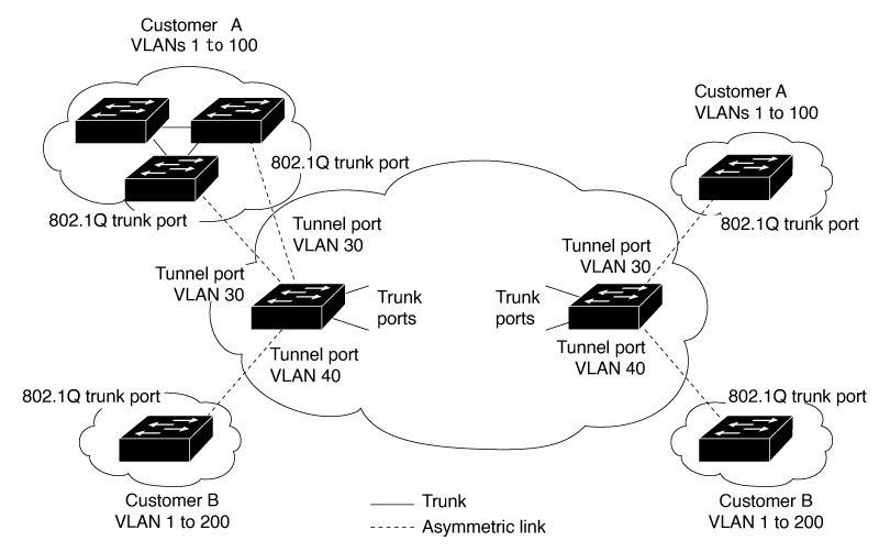
The VLAN mapping process in a service-provider network occurs in several stages.
-
- Traffic from customer A enters the service provider network through a customer-connected port at Site 1.
- The ingress port maps the customer VLAN ID to a unique service provider VLAN ID.
- The packet traverses the service provider backbone using the mapped service-provider VLAN ID.
- At the egress customer-connected port at Site 2, the service provider VLAN ID is mapped back to the original customer VLAN ID.
- The traffic reaches customer A's destination site with the original VLAN ID intact.
- The same mapping process occurs for customer B's traffic, using a different set of service provider VLAN IDs to prevent conflicts.