Configuring Precision Time Protocol

Precision time protocol

Precision Time Protocol (PTP) is a time synchronization protocol that

  • synchronizes clocks in packet-based networks that include distributed device clocks of varying precision and stability

  • requires minimal bandwidth and little processing overhead, and

  • is defined in IEEE 1588 as Precision Clock Synchronization for Networked Measurements and Control Systems.

Protocol characteristics

PTP is designed specifically for industrial, networked measurement and control systems, and is optimal for use in distributed systems.

Cisco Catalyst IE3x00 Rugged, IE3400 Heavy Duty, and ESS3300 Series Switches (referred to as the switch in the rest of the document) support PTP.

Why PTP?

Smart grid power automation applications such as peak-hour billing, virtual power generators, and outage monitoring and management, require extremely precise time accuracy and stability. Timing precision improves network monitoring accuracy and troubleshooting ability.

PTP benefits in ethernet networks

The benefits of using PTP in an Ethernet network include:

  • Low cost and easy setup in existing Ethernet networks

  • Limited bandwidth is required for PTP data packets

Ethernet switches and delays

Ethernet switches and delays are network timing challenges that

  • occur when switches buffer packets during simultaneous transmission attempts, causing timing delays,

  • result from packet processing variations during MAC address table searches and CRC verification, and

  • can cause device clocks on the network to lose synchronization with one another.

Switch delay mechanisms and PTP compensation

In an Ethernet network, switches provide a full-duplex communication path between network devices. Switches use the address information in data packets to determine their destinations. When a switch tries to send multiple packets at once, it buffers some packets to prevent loss before transmission. If the buffer becomes full, the switch delays packet transmission. This delay can cause device clocks on the network to lose synchronization with one another.

Additional delays may occur when entering packets are stored in local memory while the switch searches the MAC address table and verifies packet Cyclic Redundancy Check (CRC) fields. This process causes variations in packet-forwarding time latency, and these variations might result in asymmetrical packet-delay times.

Adding PTP to a network compensates for these latency and delay problems by correctly adjusting device clocks so that they stay synchronized with one another. PTP enables network switches to function as PTP devices, including boundary clocks and transparent clocks.


Note


To learn more about PTP clock devices and their role in a PTP network, see PTP clocks.


Message-based synchronization

Message-based synchronization is a PTP method that requires accurate measurement of communication path delay between the time source (grandmaster clock) and the time recipient. It sends messages between the time source and the time recipient to determine path delay. The method measures the exact transmit and receive times of messages to calculate communication path delay. It then adjusts current time information by the calculated delay to provide more accurate time information.

Path delay calculation and transparent clocks

This delay measurement principle determines the path delay between devices on a network. The local clocks are adjusted for this delay using a series of messages sent between the time source and the time recipient devices. The system calculates the one-way delay time by averaging the path delays of the transmit and receive messages. This calculation assumes a symmetrical communication path. However, switched networks do not necessarily have symmetrical communication paths because of the buffering process.

PTP provides a method—using transparent clocks—to measure and account for the delay in a time-interval field in network timing packets. This approach makes the switches temporarily transparent to the time source and the time recipient nodes on a network. An end-to-end transparent clock forwards all the messages in a network in the same way that a switch does.


Note


The Cisco PTP implementation supports multicast PTP messages only.


To read a detailed description of synchronization messages, refer to PTP event message sequences. To learn more about how transparent clocks calculate network delays, see PTP clocks.

This figure shows a typical 1588 PTP network that includes time source clocks, switches in boundary clock mode, and intelligent electronic devices (IEDs), such as digital relays or protection devices. In this figure, Time Source 1 is the grandmaster clock. If Time Source 1 becomes unavailable, the time recipient boundary clocks synchronize with Time Source 2.
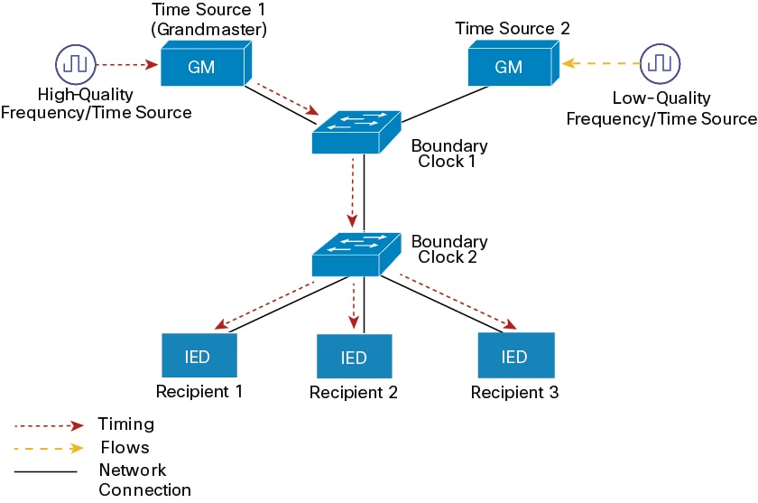
Figure 1. PTP network
A typical 1588 PTP network diagram illustrating time source clocks, boundary clock switches, and intelligent electronic devices, highlighting the role of Time Source 1 as the grandmaster clock and the failover to Time Source 2 for synchronization.

PTP event message sequences

This section describes the PTP event message sequences that occur during synchronization.

How boundary clocks synchronize

Summary

The key components involved in boundary clock synchronization are:

  • Ordinary clocks: Time recipients that receive synchronization messages

  • Boundary clocks: Time sources that send synchronization messages

  • Event messages: Communication protocol using Sync, Delay_Req, Follow_Up, and Delay_Resp messages

  • Timestamps: Four timing values (t1, t2, t3, t4) used to calculate clock offset and propagation delay

Workflow

The boundary clock synchronization process involves these stages:

  1. The time source sends a Sync message to the time recipient and notes the time (t1) at which it was sent.
  2. The time recipient receives the Sync message and notes the time of reception (t2).
  3. The time source sends the timestamp t1 to the time recipient by embedding it in a Follow_Up message.
  4. The time recipient sends a Delay_Req message to the time source and notes the time (t3) at which it was sent.
  5. The time source receives the Delay_Req message and notes the time of reception (t4).
  6. The time source sends the timestamp t4 to the time recipient by embedding it in a Delay_Resp message.

Result

After this sequence, the time recipient possesses all four timestamps. These timestamps can be used to compute the offset of the time recipient clock relative to the time source, and the mean propagation time of messages between the two clocks.

The offset calculation is based on the assumption that the time for the message to propagate from the time source to the time recipient is the same as the time required from the time recipient to the time source. This assumption is not always valid on an Ethernet network because of asymmetrical packet delay times.

How peer-to-peer transparent clocks synchronize

When a network includes multiple levels of boundary clocks in the hierarchy, with non-PTP-enabled devices between them, synchronization accuracy decreases.

The round-trip time is assumed to be equal to mean_path_delay/2. However, this is not always valid for Ethernet networks. To improve accuracy, the resident time of each intermediary clock is added to the offset in the end-to-end transparent clock. Resident time, however, does not take into consideration the link delay between peers, which is handled by peer-to-peer transparent clocks.

Peer-to-peer transparent clocks measure the link delay between two clock ports implementing the peer delay mechanism. The link delay is used to correct timing information in Sync and Follow_Up messages.

Summary

The key components involved in peer-to-peer transparent clock synchronization are:

  • Port 1: Initiates the synchronization process by generating and receiving timing messages

  • Port 2: Responds to timing messages and provides timestamp information

  • Event messages: Pdelay_Req, Pdelay_Resp, and Pdelay_Resp_Follow_Up messages that carry timing information

  • Timestamps: Four time values (t1, t2, t3, t4) used to calculate mean link delay

Workflow
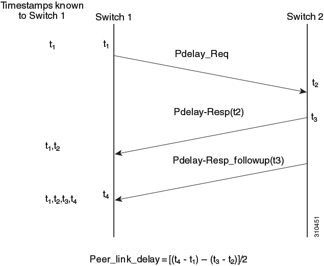
Figure 2. Detailed Steps—Peer-to-Peer transparent clock synchronization
The image illustrates the detailed steps involved in peer-to-peer transparent clock synchronization, highlighting the timing messages exchanged between ports and the timestamps generated during the process.

These stages describe how peer-to-peer transparent clocks synchronize using event messages:

  1. Port 1 generates timestamp t1 for a Pdelay_Req message.
  2. Port 2 receives and generates timestamp t2 for this message.
  3. Port 2 returns and generates timestamp t3 for a Pdelay_Resp message. To minimize errors caused by frequency offset between the two ports, Port 2 returns the Pdelay_Resp message as quickly as possible after the receipt of the Pdelay_Req message.
  4. Port 2 returns timestamps t2 and t3 in the Pdelay_Resp and Pdelay_Resp_Follow_Up messages respectively.
  5. Port 1 generates timestamp t4 after receiving the Pdelay_Resp message. Port 1 then uses the four timestamps (t1, t2, t3, and t4) to calculate the mean link delay.

Synchronizing the local clock

In a PTP network, drift compensation uses timestamp information and follow-up messages in device hardware to adjust the local clock frequency so it matches the time source clock.

Clock drift in PTP networks

In an ideal PTP network, the time source and the time recipient clocks operate at the same frequency. However, drift might occur on the network. Drift is the frequency difference between the time source and the time recipient clocks.

Best master clock algorithm

The Best Master Clock Algorithm (BMCA) is the basis of PTP functionality that

  • specifies how each clock on the network determines the best time source clock in its subdomain of all the clocks it can see, including itself,

  • runs on the network continuously and quickly adjusts for changes in network configuration, and

  • prevents clock conflicts on the PTP network.

Time source clock selection criteria

The BMCA uses several criteria to determine the best time source clock in the subdomain.

  • Clock quality, for example, GPS is considered the highest quality

  • Clock accuracy of the clock's time base

  • Stability of the local oscillator

  • Closest clock to the grandmaster

The BMCA also prevents clock conflicts on the PTP network by ensuring that:

  • Clocks do not have to negotiate with one another.

  • There is no misconfiguration, such as two time source clocks or no time source clocks, as a result of the time source clock identification process.

PTP clocks

PTP clocks are PTP-enabled network devices that provide time synchronization, consist of different clock types based on their network role, and work together to maintain accurate time across the network.

PTP clock types

A PTP network is made up of PTP-enabled devices and devices that are not using PTP. The PTP-enabled devices typically consist of these clock types.

Grandmaster clock

  • Within a PTP domain, the grandmaster clock (GMC) is the primary source of time for clock synchronization using PTP. The GMC usually uses a highly precise time source, such as GPS or an atomic clock. When the network does not require any external time reference and only needs to be synchronized internally, the GMC can be free-running.

  • The switch can function as a hybrid grandmaster boundary clock using NTP as its source. For more information, see NTP to PTP time conversion.

Ordinary clock

  • An ordinary clock is a PTP clock with a single PTP port. It functions as a node in a PTP network.Ordinary clocks are the most common clock type on a PTP network because they serve as end nodes connected to devices requiring synchronization. Ordinary clocks have various interfaces to external devices.

Boundary clock

  • A boundary clock in a PTP network operates in place of a standard network switch or router. Boundary clocks have more than one PTP port. Each port provides access to a separate PTP communication path. Boundary clocks provide an interface between PTP domains. They intercept and process all PTP messages and pass other network traffic. The boundary clock uses the BMCA to select the best clock seen by any port. The selected port is then configured not to be a time source. The time source port synchronizes the clocks connected downstream, while the port that is not a time source synchronizes with the upstream time source clock.

Transparent clock

  • Transparent clocks in a PTP network update the time interval field included in a PTP event message. This update compensates for switch DELAY and achieves an accuracy within one picosecond.

There are two types of transparent clocks:

  • End-to-end (E2E) transparent clocks measure the PTP event message transit time (also known as resident time) for SYNC and DELAY_REQUEST messages. This measured transit time is added to a data field (correction field) in the corresponding messages:

    • The measured transit time of a SYNC message is added to the correction field of the corresponding SYNC or the FOLLOW_UP message.

    • The measured transit time of a DELAY_REQUEST message is added to the correction field of the corresponding DELAY_RESPONSE message.

    The time recipient uses this information when determining the offset between the time recipient's and the time source's time. E2E transparent clocks do not provide correction for the propagation DELAY of the link itself.

  • Peer-to-peer (P2P) transparent clocks measure PTP event message transit time in the same way E2E transparent clocks do, as described above. In addition, P2P transparent clocks measure the upstream link DELAY. The upstream link DELAY is the estimated packet propagation DELAY between the upstream neighbor P2P transparent clock and the P2P transparent clock under consideration.

    These two times (message transit time and upstream link DELAY time) are both added to the correction field of the PTP event message. The correction field of the message received by the time recipient contains the sum of all link delays. In theory, this is the total end-to-end DELAY (from time source to time recipient) of a SYNC packet.

This figure illustrates PTP clocks in a time source-time recipient hierarchy within a PTP network.
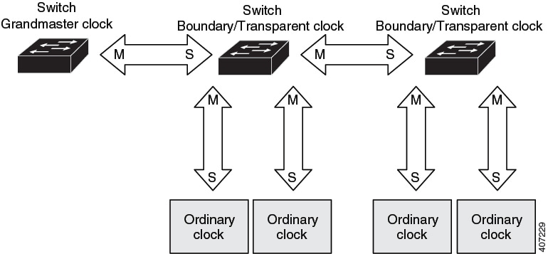
Figure 3. PTP clock hierarchy
PTP clocks are organized in a time source-time recipient hierarchy within a PTP network, illustrating the relationship and flow of time synchronization messages.

PTP profiles

A PTP profile is a set of allowed PTP features applicable to a device that is specific to a particular type of application or environment. It defines configuration values for BMCA options, path delay mechanisms, and transport mechanisms. It also specifies node types and options that are required, permitted, or prohibited.

PTP profile types

The switch supports these PTP profiles:

  • Power Profile

  • Default Profile

The Power Profile is defined in PC37.238-2011 - IEEE Draft Standard Profile for Use of IEEE 1588 Precision Time Protocol in Power System Applications. The Cisco PTP implementation uses the terms Power Profile mode and Default Profile mode when referring to this IEEE 1588 profile and its associated configuration values.

A PTP profile defines these values:

  • BMCA options

  • Configuration management options

  • Path delay mechanisms (peer delay or delay request-response)

  • Range and default values of all PTP configurable attributes and data set members

  • Transport mechanisms that are required, permitted, or prohibited

  • Node types that are required, permitted, or prohibited

  • Options that are required, permitted, or prohibited

Default profile mode

Default profile mode is a PTP profile mode that uses Layer 3 as the PTP transport mode. It supports end-to-end (E2E) as the transparent clock mode and serves as the default PTP profile mode on the switch.

Default profile configuration details

The Default profile uses Layer 3 transport multicast address 224.0.1.129 (MAC address 01-00-5e-00-01-81) for all PTP messages.

Refer to Power profile mode for a list of the configuration values for the switch in Default Profile and Power Profile modes.

Power profile mode

Power profile mode is a PTP configuration mode that uses specific values defined in the IEEE 1588 Power Profile standard for PTP networks in power substations. It includes optimum physical layer settings, higher-level protocols for PTP messages, and preferred BMCA configurations. This setup ensures consistent and reliable network time distribution within substations, between substations, and across wide geographic areas.

Switch optimization for PTP

The switch is optimized for PTP in these ways:

  • Hardware: The switch uses FPGA and PHY for the PTP function. The PHY time-stamps the Fast Ethernet and Gigabit Ethernet ports.

  • Software: In Power Profile mode, the switch uses the configuration values defined in the IEEE 1588 Power Profile standard.

The table compares configuration values defined by the IEEE 1588 Power Profile and the values the switch uses for each PTP profile mode.

Table 1. Configuration values for the IEEE PTP power profile and switch modes

PTP Field

Power Profile Value

Switch Configuration Value

Power Profile Mode

Default Profile Mode

Message transmission

Ethernet 802.3 with Ethertype 0X88F7. PTP messages are sent as 802.1Q- tagged Ethernet frames with a default VLAN 0 and default priority 4.

Access Ports : Untagged Layer 2 packets.

Trunk Ports : 802.1Q tagged Layer 2 packets with native VLAN on the port and default priority value of 4.

Layer 3 packets. By default, 802.1q tagging is disabled.

MAC address : Nonpeer delay messages

01-1B-19-00-00-00.

01-1B-19-00-00-00.

01-00-5e-00-01-81.

MAC address : Peer delay messages

01-80-C2-00-00-0E.

01-80-C2-00-00-0E.

Not applicable to this mode.

Domain number

0.

0.

0.

Path delay calculation

Peer-to-peer transparent clocks.

Peer-to-peer transparent clocks using the peer_delay mechanism.

End-to-end transparent clocks using the delay_request mechanism.

BMCA

Enabled.

Enabled.

Enabled.

Clock type

Two-step clocks are supported.

Two-step.

Two-step.

Time scale

Epoch.1

Epoch.

Epoch.

Grandmaster ID and local time determination

PTP-specific TLV (type, length, value) to indicate Grandmaster ID.

PTP-specific TLV to indicate Grandmaster ID.

PTP-specific type, length, and value to indicate Grandmaster ID.

Time accuracy over network hops

Over 16 hops, the time recipient device synchronization accuracy is within 1 usec (1 microsecond).

Over 16 hops, the time recipient device synchronization accuracy is within 1 usec (1 microsecond).

Not applicable in this mode.

1 Epoch = Elapsed time since epoch start.

Tagging behavior for PTP packets

This table describes the switch tagging behavior in Power Profile and Default Profile modes for PTP packets.

Table 2. Tagging behavior for PTP packets

Switch Port Mode

Configuration

Power Profile Mode

Default Profile Mode

Behavior

Priority

Behavior

Priority

Trunk Port

vlan dot1q tag native enabled

Switch tags packets

7

Switch tags packets

7

Trunk Port

vlan dot1q tag native disabled

PTP software tags packets

4

Untagged

None

Access Port

N/A

Untagged

None

Untagged

None

PTP clock modes supported on the switch

PTP synchronization behavior depends on the PTP clock mode that you configure on the switch. You can configure the switch for one of the global modes described in this reference.

See PTP configuration and mode limitations for guidelines to configure each of the clock modes.

Grandmaster-Boundary clock mode

The switch can function as a hybrid grandmaster boundary clock using NTP as its source. For more information, see NTP to PTP time conversion.

Boundary clock mode

A switch configured for boundary clock mode participates in selecting the best time source clock on the subdomain, selecting from all the clocks it can see, including itself. "If the switch does not detect a more accurate clock than itself, it becomes the time source clock. If the switch detects a more accurate clock, it synchronizes to that clock and becomes a time recipient clock.

After initial synchronization, the switch and the connected devices exchange PTP timing messages to correct the changes caused by clock offsets and network delays.

Forward mode

A switch configured for forward mode passes incoming PTP packets as normal multicast traffic.

E2E transparent clock mode

A switch configured for end-to-end transparent clock mode does not synchronize its clock with the time source clock. A switch in this mode does not participate in time source clock selection and uses the default PTP clock mode on all ports.

P2P transparent clock mode

A switch configured for peer-to-peer transparent clock mode does not synchronize its clock with the time source clock. A switch in this mode does not participate in time source clock selection and uses the default PTP clock mode on all ports.

Configurable boundary clock synchronization algorithm

A configurable boundary clock synchronization algorithm is a PTP mechanism that accommodates various PTP use cases, depending on whether you need to prioritize filtering of input time errors or faster convergence. It provides three synchronization options (feedforward, adaptive, and linear) that comply with IEEE 1588-2008. This approach allows BCs to use different algorithms to control time output based on specific network requirements.

BC synchronization algorithm options

By default, the BC uses a linear feedback controller (that is, a servo) to set the BC's time output to the next clock. The linear servo provides a small amount of PDV filtering and converges in an average amount of time. For improved convergence time, BCs can use the TC feedforward algorithm to measure the delay added by the network elements' forwarding plane (the disturbance). BCs then use that measured delay to control the time output.

While the feedforward BC dramatically speeds up the boundary clock, the feedforward BC does not filter any PDV. The adaptive PDV filter provides high-quality time synchronization when PDV is present over wireless access points (APs) and enterprise switches that do not support PTP and add significant PDV.

A PTP algorithm that filters packet delay variation (PDV) converges more slowly than a PTP algorithm that does not.

Three options are available for BC synchronization:

  • Feedforward—For very fast and accurate convergence; no PDV filtering.

  • Adaptive—Filters as much PDV as possible, given a set of assumptions about the PDV characteristics, the hardware configuration, and the environmental conditions.


    Note


    With the adaptive filter, the switch does not meet the time performance requirements specified in ITU-T G.8261.
  • Linear—Provides simple linear filtering (the default).

Adaptive mode (ptp transfer filter adaptive) is not available in Power Profile mode.

For configuration information, see PTP switch configuration.
NTP to PTP time conversion

NTP to PTP time conversion is a synchronization feature that allows you to use Network Time Protocol (NTP) as a time source for PTP. This feature enables customers who require very precise synchronization within a site to use PTP, and to use NTP across sites where precision is not required. It also allows customers to correlate data generated in their PTP network with data in their enterprise data centers running NTP.

NTP time synchronization background

NTP is the traditional method of synchronizing clocks across packet based networks. NTP uses a two-way time transfer mechanism between a time source and an end device. NTP is capable of synchronizing a device within a few hundred milliseconds across the Internet and within a few milliseconds in a tightly controlled LAN.


Note


Beginning with the Cisco IOS XE Dublin 17.12.x release, Cisco Catalyst IE3100 Rugged Series Switches are supported for NTP to PTP time conversion.


Industrial network time synchronization implementation

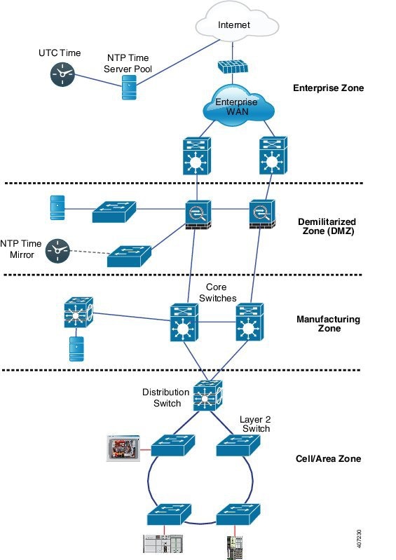
The example illustrates an industrial network based on the Industrial Automation and Control System Reference Model. The enterprise zone and demilitarized zone run NTP, and the manufacturing zone and cell/area zone run PTP with NTP as the time source. The switch with the NTP to PTP conversion feature can be either the Layer 2 Switch or the Distribution Switch in the Cell/Area Zone.

This figure illustrates an industrial network time synchronization setup, highlighting the use of NTP in the enterprise and demilitarized zones, while PTP is utilized in the manufacturing and cell/area zones, with NTP serving as the time source. The switch capable of NTP to PTP conversion is identified as either the Layer 2 Switch or the Distribution Switch within the Cell/Area Zone.

Grandmaster boundary clock hybrid

A grandmaster boundary clock hybrid (GMC-BC) is a PTP clock type that

  • adds grandmaster clock functionality to Cisco PTP, enabling the switch to be a time source as well as forward time,

  • provides an NTP time source for PTP networks by converting NTP to PTP,

  • acts as a boundary clock (BC), a multi-port device in which a single-port GMC is connected to a virtual port on the BC, and

  • switches between acting like a GMC when the GMC-BC is the primary GMC and acting like a BC when the GMC-BC is a backup.

Redundant GMC-BC configuration

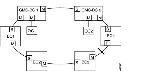
The GMC-BC ensures that all devices on the PTP network remain synchronized in a failover scenario. This figure shows a PTP network with redundant GMC-BCs where GMC-BC 1 is the grandmaster clock, and GMC-BC 2 is both backup GMC and BC.

Figure 4. Redundant GMC-BC configuration
The figure illustrates a PTP network with two redundant Grandmaster Boundary Clocks (GMC-BCs), where GMC-BC 1 serves as the primary grandmaster clock and GMC-BC 2 functions as both a backup grandmaster clock and boundary clock, ensuring synchronization during failover scenarios.

In a network with two GMC-BCs, the secondary GMC-BC can synchronize to both the NTP reference and the PTP reference at the same time, so the secondary GMC-BC can immediately take over when the primary GMC-BC fails. The GMC-BC instantly updates the time during a switchover.

Clock manager

A clock manager is a component in the Cisco NTP to PTP software architecture that

  • keeps track of the various time services and selects the clock that actively provides time

  • notifies the time services of important changes, including state changes, leap seconds, or daylight saving time, and

  • selects the NTP or manually set clock first. If NTP is not active, it selects PTP and the real-time clock.

Time service selection process

This table shows the results of the clock selection process.

Table 3. Time service selection

NTP (Active) or Manually Set

PTP (Active)

Real-Time Clock

Selected Output

True

Don't care

Don't care

NTP or Manually Set

False

True

Don't care

PTP

False

False

True

Real-Time Clock

In general, the clock manager ensures that the time displayed in the Cisco IOS XE commands show ptp clock and show clock match. The show clock command always follows this priority, but there are two corner cases where the show ptp clock time may differ:

  • The switch is either a TC or a BC, and there is no other active reference on the network. To preserve backward compatibility, the TC and BC never take their time from the clock manager; they only obtain their time from the network's PTP GMC. If there is no active PTP GMC, then the time displayed in the show clock and the show ptp clock command output may differ.

  • The switch is a syntonizing TC, a BC with a time recipient port, or a GMC-BC with time recipient port, and the time provided by the PTP GMC does not match the time provided by NTP or the user (that is, manually set). In this case, the PTP clock must forward the time from the PTP GMC. If the PTP clock does not follow the PTP GMC, then the PTP network will end up with two different time bases, which would break any control loops or sequence of event applications using PTP.

This table shows how the Cisco IOS XE and PTP clocks behave given the various configurations. Most of the time, the two clocks match. Sometimes, the two clocks are different. These configurations are highlighted in the table.

Table 4. Expected time flow

IOS XE Clock Configuration

PTP Clock Configuration

IOS XE Clock Source

PTP Clock Source

Calendar

PTP BC, E2E TC, or GMC-BC in BC Mode

PTP

PTP

Manual

PTP BC, E2E TC, or GMC-BC in BC Mode

Manual

PTP

NTP

PTP BC, E2E TC, or GMC-BC in BC Mode

NTP

PTP

Calendar

GMC-BC in GM Mode

Calendar

Calendar

Manual

GMC-BC in GM Mode

Manual

Manual

NTP

GMC-BC in GM Mode

NTP

NTP

Requirements for NTP to PTP conversion

Before configuring NTP to PTP conversion, ensure that you meet these requirements:

  • Review the PTP configuration and mode limitations.

  • Configure an IP address for NTP to function on the switch when using the NTP to PTP conversion feature.

  • Configure at least one NTP server for the NTP to PTP conversion feature. Configuring three or more NTP servers allows NTP to ignore bad clocks.


Note


For information about configuring NTP, see Basic System Management Configuration Guide, Cisco IOS XE 17, Network Time Protocol.


PTP configuration and mode limitations

PTP messages

  • The Cisco PTP implementation supports only two-step clock operation in BC mode; one-step clock is not supported.

  • In transparent clock mode, the switch converts any one-step Sync message received from the grandmaster clock into a two-step message.

  • Cisco PTP supports multicast PTP messages only.

PTP mode and profile

  • The switch and the grandmaster clock must be in the same PTP domain.

  • When Power Profile mode is enabled, the switch drops the PTP announce messages that do not include these two Type, Length, Value (TLV) message extensions: Organization_extension and Alternate_timescale.

    If the grandmaster clock is not compliant with PTP and sends announce messages without these TLVs, configure the switch to process the announce message by entering the PTPallow-without-TLV command.

    Refer to Configure PTP power profile mode on the switch for a complete description of this command.

  • When the switch is in Power Profile mode, only the peer_delay mechanism is supported.

    To change to boundary clock mode and the peer_delay mechanism, enter the PTPmodeboundarypdelay-req command.

  • In Default Profile mode, only the delay_request mechanism is supported.

    To change to boundary clock mode with the delay_request mechanism, enter the PTP mode boundary delay-req command.

Refer to Configure default profile mode on the switch for a complete description of commands.

Packet format

  • The packet format for PTP messages can be 802.1q tagged packets or untagged packets.

  • The switch does not support 802.1q QinQ tunneling.

  • In switch Power Profile mode:

    • When the PTP interface is configured as an access port, PTP messages are sent as untagged, Layer 2 packets.

    • When the PTP interface is configured as a trunk port, PTP packets are sent as 802.1q tagged Layer 2 packets over the port native VLAN.

  • Time recipient IEDs must support tagged and untagged packets.

  • When PTP packets are sent on the native VLAN in E2E transparent clock mode, they are sent as untagged packets. To configure the switch to send them as tagged packets, enter the global VLANdot1qtagnative command.

VLAN configuration

  • Sets the PTP VLAN on a trunk port. The range is from 1 to 4094. The default is the native VLAN of the trunk port.

  • In boundary mode, only PTP packets in PTP VLAN will be processed, PTP packets from other VLANs will be dropped.

  • Before configuring the PTP VLAN on an interface, the PTP VLAN must be created and allowed on the trunk port.

  • Most grandmaster clocks use the default VLAN 0. In Power Profile mode, the switch default VLAN is VLAN 1 and VLAN 0 is reserved. When you change the default grandmaster clock VLAN, it must be changed to a VLAN other than 0.

  • When VLAN is disabled on the grandmaster clock, the PTP interface must be configured as an access port.

Clock configuration

  • All PHY PTP clocks are synchronized to the grandmaster clock. The system clock of the switch is not synchronized during PTP configuration or operation.

  • When VLAN is enabled on the grandmaster clock, it must be in the same VLAN as the native VLAN of the PTP port on the switch.

  • Grandmaster clocks can drop untagged PTP messages when a VLAN is configured on the grandmaster clock. To force the switch to send tagged packets to the grandmaster clock, enter the global VLANdot1qtagnative command.

Clock modes

Boundary Clock Mode

  • You can enable this mode when the switch is in Power Profile mode (Layer 2) or in Default Profile mode (Layer 3).

Forward Mode

  • You can enable this mode when the switch is in Power Profile mode (Layer 2) or in Default Profile mode (Layer 3).

  • When the switch is in Forward mode, the only global configuration available is the CLI command to switch to a different PTP mode (that is, boundary, e2etransparent, or p2ptransparent).

E2E Transparent Clock Mode

  • You can enable this mode only when the switch is in Default Profile mode (Layer 3).

  • When the switch is in E2E Transparent mode, the only global configurations available from CLI commands are to switch to a different PTP mode (boundary, forward, or GMC-BC), and change the domain.

P2P Transparent Clock Mode

  • You can enable this mode only when the switch is in Power Profile mode (Layer 2).

GMC-BC Clock Mode

  • You can enable this mode when the switch is in Default Profile mode or in Power Profile mode.

PDV filtering

Adaptive mode (ptp transfer filter adaptive ) is not available in Power Profile mode.

PTP interaction with other features

PTP clock mode limitations with EtherChannels and VLANs.

  • These PTP clock modes do not support EtherChannels: e2etransparent, p2ptransparent, boundary delay-req, boundary pdelay-req

  • These PTP clock modes only operate on a single VLAN: e2etransparent, p2ptransparent

PTP support with resiliency protocols varies by platform. Use this table to determine whether PTP is supported over a resiliency protocol on each Cisco IE switch platform.

NTP to PTP conversion

The NTP to PTP feature supports the Default E2E Profile and Power Profile.


Note


Refer to Configure default profile mode on the switch for a complete description of commands.


Note


PTP is not supported for GLC-T transceivers at 100 Mbps on Cisco Catalyst IE3x00 Rugged Series fiber ports.


Default settings

This reference provides the default PTP configuration settings that are automatically applied when the switch is initialized or when specific configuration parameters are not explicitly defined.

  • PTP is enabled on the switch by default.

  • By default, the switch uses configuration values defined in the Default Profile (Default Profile mode is enabled).

  • The switch default PTP clock mode is E2E Transparent clock mode.

  • The default BC synchronization algorithm is linear filter.

  • PTP alarms are disabled by default.

PTP switch configuration

PTP switch configuration is a network setup process that enables Precision Time Protocol functionality on network switches to provide high-precision time synchronization across network devices.

Configuration procedures

Use one of the procedures in this section to configure the switch for PTP.


Note


To configure the switch for grandmaster-boundary clock mode (gmc-bc), see Configure NTP to PTP time conversion.


Note


On the ESS3300, the 10 GE ports do not support PTP. Only ports gi1/3-gi1-10 and gi2/1-gi2/16 support PTP.

Configure PTP power profile mode on the switch

This task enables you to configure the Precision Time Protocol (PTP) Power Profile on your switch, allowing it to participate in time synchronization networks with enhanced power grid applications support.

This section describes how to configure the switch to use the PTP Power Profile and operate in Power Profile mode.

Before you begin

These are some guidelines for configuring the Power Profile on the switch:

  • When you enter no with PTP port configuration commands, the specified port property is set to the default value.

  • To determine the value in seconds for the PTP global command interval variable, use a logarithmic scale. Below are examples of the interval variable value converted to seconds with a logarithmic scale:

Value Entered

Logarithmic Calculation

Value in Seconds

-1

2 -1

1/2

0

2 0

1

Follow these steps to configure PTP Power Profile mode on the switch:

Procedure


Step 1

Use the configure terminal command to enter global configuration mode. Then, enter the ptp profile power command to set the Power Profile.

Example:

Device(config)# ptp profile power

Step 2

Use the ptp {mode boundary pdelay-req | p2ptransparent | forward | gmc-bc} command to specify the synchronization clock mode.

Example:

Device(config)# ptp mode boundary pdelay-req
  • mode boundary pdelay-req —Configures the switch for boundary clock mode using the delay-request mechanism. In this mode, the switch participates in the selection of the most accurate time source clock. Use this mode when overload or heavy load conditions produce significant delay jitter.

  • mode p2ptransparent —Configures the switch for peer-to-peer transparent clock mode and synchronizes all switch ports with the time source clock. The link delay time between the participating PTP ports and the message transit time is added to the resident time. Use this mode to reduce jitter and error accumulation. This is the default in Power Profile mode.

  • mode forward —Configures the switch to pass incoming PTP packets as normal multicast traffic.

  • mode gmc-bc —Configures the switch for grandmaster-boundary clock mode. See Configuring NTP to PTP Time Conversion to configure the switch for this mode.

Step 3

(Optional) Use the ptp allow-without-tlv command to specify TLV settings for BC and TC modes.

Example:

Device(config)# ptp allow-without-tlv

Note


Using this command when switch mode is p2ptransparent allows the switch to operate in PTP networks where IEC61850-9-3 is required.

Step 4

(Optional) Use the ptp domain domain-number command to specify the PTP clock domain for BC and TC modes.

Example:

Device(config)# ptp domain 10

domain-number—A number from 0 to 255.

The participating grandmaster clock, switches, and time recipient devices should be in the same domain.

Step 5

(Optional) Use the ptp packet priority command to specify the packet priority for BC and TC modes.

Example:

Device(config)# ptp packet priority 4

The PTP packets have a default priority of 4.

Step 6

(Optional) Use the ptp priority1 priority priority2 priority command to specify the BMCA priority for BC mode.

Example:

Device(config)# ptp priority1 100 priority2 100
  • priority1 priority— Overrides the default criteria (such as clock quality and clock class) for the most accurate time source clock selection.

  • priority2 priority— Breaks the tie between two switches that match the default criteria. For example, enter 2 to give a switch priority over identical switches.

  • priority A priority number from 0 to 255. The default is 128.

Note


A lower value has higher priority.

Step 7

(Optional) Use the ptp time-property persist {value | infinite} command to specify time-property preservation for BC mode.

Example:

Device(config)# ptp time-property persist infinite
  • value Time duration, in seconds, from 0-100000. The default is 300.

  • infinite Time properties are preserved indefinitely.

Preserving the time properties prevents time recipient clocks from detecting a variance in the time values when the redundant GMC comes out of standby.

Step 8

(Optional) Use the ptp transfer {feedforward | filter linear} command to specify the BC synchronization algorithm.

Example:

Device(config)# ptp transfer feedforward
  • feedforward —Very fast and accurate. No PDV filtering.

  • filter linear —Provides a simple linear filter (default).

Step 9

(Optional) Use the interface interface-id command to enter interface configuration mode. Then, use the ptp command to specify port settings.

Example:

Device(config-if)# ptp enable

Boundary pdelay-req mode:

ptp {announce {interval value | timeout value } | pdelay-req interval value | enable | sync {interval value | limit value } | vlan value }

p2ptransparent mode:

ptp {pdelay-req interval value | enable | sync limit value | vlan value }

  • announce interval value —Sets the logarithmic mean interval in seconds to send announce messages. The range is 0 to 4. The default is 1 (2 seconds).

  • announce timeout value —Sets the logarithmic mean interval in seconds to announce timeout messages. The range is 2 to 10. The default is 3 (8 seconds).

  • pdelay-req interval value —Sets the logarithmic mean interval in seconds for time recipient devices to send pdelay request messages when the port is in the time source clock state. The range is -3 to 5. The default is 0 (1 second).

  • enable —Enables PTP on the port base module.

  • sync interval value —Sets the logarithmic mean interval in seconds to send synchronization messages. The range is –2 to 1. The default is 1 second.

  • sync limit value —Sets the maximum clock offset value before PTP attempts to resynchronize. The range is from 50 to 500000000 nanoseconds. The default is 10000 nanoseconds.

  • vlan value —Sets the PTP VLAN on a trunk port. The range is from 1 to 4094. The default is the native VLAN of the trunk port. In boundary mode, only PTP packets in PTP VLAN will be processed, PTP packets from other VLANs will be dropped. Before configuring the PTP VLAN on an interface, the PTP VLAN must be created and allowed on the trunk port.


The switch is configured with PTP Power Profile mode and will participate in time synchronization according to the specified clock mode and settings. The configuration is active and ready to synchronize with other PTP devices in the network.

The following example configures the switch for P2P transparent mode (the default in Power Profile mode), specifies allow-without-tlv PTP message processing, and uses default values for all PTP interval settings:

Device(config)# ptp allow-without-tlv

The following example configures the switch for boundary clock mode using the peer delay request (pdelay-req) mechanism and uses default values for all PTP interval settings:

Device(config)# ptp mode boundary pdelay-req

Configure default profile mode on the switch

Configure the switch to operate in Default Profile mode to enable proper PTP packet handling and time synchronization in your network environment.

This section describes how to configure the switch to operate in Default Profile mode.

The switch sends untagged PTP packets on the native VLAN when the switch port connected to the grandmaster clock is configured as follows:

  • Switch is in Default Profile mode.

  • Switch is in trunk mode.

  • VLAN X is configured as the native VLAN.

When the grandmaster clock requires tagged packets, make one of the following configuration changes:

  • Force the switch to send tagged frames by entering the global vlan dot1q tag native command.

  • Configure the grandmaster clock to send and receive untagged packets. If you make this configuration change on the grandmaster clock, you can configure the switch port as an access port.

Before you begin

These are some guidelines for configuring the Default Profile on the switch:

  • When you enter no with PTP port configuration commands, the specified port property is set to the default value.

  • To determine the value in seconds for the PTP global command interval variable, use a logarithmic scale. Below are examples of the interval variable value converted to seconds with a logarithmic scale:

Value Entered

Logarithmic Calculation

Value in Seconds

-1

2 -1

1/2

0

2 0

1

Follow these steps to configure Default Profile mode on the switch:

Procedure


Step 1

Use the configure terminal command to enter global configuration mode. Then, use the ptp {mode boundary delay-req | e2etransparent | forward | gmc-bc} command to specify the synchronization clock mode.

Example:

Device(config)# ptp mode boundary delay-req
  • mode boundary delay-req —Configures the switch for boundary clock mode using the delay-request mechanism. In this mode, the switch participates in the selection of the most accurate time source clock. Use this mode when overload or heavy load conditions produce significant delay jitter.

  • mode e2etransparent —Configures the switch for end-to-end transparent clock mode. A switch clock in this mode synchronizes all switch ports with the time source clock. This switch does not participate in time source clock selection and uses the default PTP clock mode on all ports. This is the default clock mode. The message transit time is added to the resident time. Use this mode to reduce jitter and error accumulation.

  • mode forward —Configures the switch to pass incoming PTP packets as normal multicast traffic.

  • mode gmc-bc —Configures the switch for grandmaster-boundary clock mode. See Configure NTP to PTP time conversion to configure the switch for this mode.

Step 2

(Optional) Use the ptp domain domain-number command to specify the PTP clock domain for BC and TC modes.

Example:

Device(config)# ptp domain 10

domain-number A number from 0 to 255.

The participating grandmaster clock, switches, and time recipient devices should be in the same domain.

Step 3

(Optional) Use the ptp priority1 priority priority2 priority command to specify the BMCA priority for BC mode.

Example:

Device(config)# ptp priority1 100 priority2 100
  • priority1 priority— Overrides the default criteria (such as clock quality and clock class) for the most accurate time source clock selection.

  • priority2 priority— Breaks the tie between two switches that match the default criteria. For example, enter 2 to give a switch priority over identical switches.priority A priority number from 0 to 255. The default is 128.

Step 4

(Optional) Use the ptp time-property persist {value | infinite} command to specify time-property preservation for BC mode.

Example:

Device(config)# ptp time-property persist infinite
  • value Time duration, in seconds, from 0-100000. The default is 300.

  • infinite Time properties are preserved indefinitely.

Preserving the time properties prevents time recipient clocks from detecting a variance in the time values when the redundant GMC comes out of standby.

Step 5

(Optional) Use the ptp transfer {feedforward | filter {adaptive | linear}} command to specify the BC synchronization algorithm.

Example:

Device(config)# ptp transfer feedforward
  • feedforward —Very fast and accurate. No PDV filtering.

  • filter adaptive —Automatically filters as much PDV as possible.

  • filter linear —Provides a simple linear filter (default).

Step 6

(Optional) Use the interface interface-id command to enter interface configuration mode. Then, use the ptp command to specify port settings.

Example:

Device(config-if)# ptp enable

Boundary delay-req mode:

ptp {announce {interval value | timeout value } | delay-req interval value | enable | sync {interval value | limit value } | vlan value }

e2etransparent mode:

ptp {enable | sync {interval value | limit value }}

  • announce interval value —Sets the logarithmic mean interval in seconds to send announce messages. The range is 0 to 4. The default is 1 (2 seconds).

  • announce timeout value — Sets the logarithmic mean interval in seconds to announce timeout messages. The range is 2 to 10. The default is 3 (8 seconds).

  • delay-req interval value —Sets the logarithmic mean interval in seconds for time recipient devices to send delay request messages when the port is in the time source clock state. The range is -2 to 6. The default is -5 (1 packet every 1/32 seconds, or 32 packets per second).

  • enable —Enables PTP on the port base module.

  • sync interval value —Sets the logarithmic mean interval in seconds to send synchronization messages. The range is –2 to 1. The default is 1 second.

  • sync limit value —Sets the maximum clock offset value before PTP attempts to resynchronize. The range is from 50 to 500000000 nanoseconds. The default is 500000000 nanoseconds.

  • vlan value —Sets the PTP VLAN on a trunk port. The range is from 1 to 4094. The default is the native VLAN of the trunk port. In boundary mode, only PTP packets in PTP VLAN will be processed, PTP packets from other VLANs will be dropped. Before configuring the PTP VLAN on an interface, the PTP VLAN must be created and allowed on the trunk port.

Step 7

Use the end command to return to privileged EXEC mode.

Example:

Device(config-if)# end

Step 8

(Optional) Use the show running-config command to verify your entries.

Example:

Device# show running-config

Step 9

(Optional) Use the copy running-config startup-config command to save your entries in the configuration file.

Example:

Device# copy running-config startup-config

The switch is configured for Default Profile mode with the specified synchronization clock mode and optional settings. PTP packets are handled according to the configured mode and VLAN settings.

Verify configuration

Use the show PTP commands to verify and display various PTP configuration properties including clock information, foreign master records, parent properties, port settings, and time properties.

Command

Purpose

show PTP {clock|foreign-master-records|parent|port{FastEthernet|GigabitEthernet} | time-property} | histogram | history | internal-info

Identifies the type of PTP information to display.
  • clock—Displays PTP clock information.

  • foreign-master-records—Displays PTP foreign-master-records.

  • parent—Displays PTP parent properties.

  • port FastEthernet—Displays PTP properties for the FastEthernet IEEE 802.3 interfaces.

  • port GigabitEthernet—Displays PTP properties for the GigabitEthernet IEEE 802.3z interfaces.

  • time-property—Displays PTP clock-time properties.

  • histogram—Displays PTP offset, delay, or time-error data.

  • history—Displays PTP historical data.

  • internal-info—Displays PTP offset.

Power profile example


switch# show ptp parent
 PTP PARENT PROPERTIES
  Parent Clock:
  Parent Clock Identity: 0xA4:C:C3:FF:FE:BF:B4:0
  Parent Port Number: 23
  Observed Parent Offset (log variance): N/A
  Observed Parent Clock Phase Change Rate: N/A
  Grandmaster Clock:
  Grandmaster Clock Identity: 0xA4:C:C3:FF:FE:BF:2B:0
  Grandmaster Clock Quality:
        Class: 248
        Accuracy: Unknown
        Offset (log variance): N/A
        Priority1: 128
        Priority2: 128
switch# show ptp clock
 PTP CLOCK INFO
  PTP Device Type: Boundary clock
  PTP Device Profile: Power Profile
  Clock Identity: 0xA4:C:C3:FF:FE:BF:E0:80
  Clock Domain: 0
  Number of PTP ports: 26
  PTP Packet priority: 4
  Priority1: 128
  Priority2: 128
  Clock Quality:
        Class: 248
        Accuracy: Unknown
        Offset (log variance): N/A
  Offset From Master(ns): 25
  Mean Path Delay(ns): 705
  Steps Removed: 4
  Local clock time: 14:23:56 PST Apr 5 2013
switch# show ptp foreign-master-record
PTP FOREIGN MASTER RECORDS
 Interface GigabitEthernet1/1
   Foreign master port identity: clock id: 0xF4:4E:5:FF:FE:E5:82:0
   Foreign master port identity: port num: 1
   Number of Announce messages: 4
   Message received port: 1
   Time stamps: 1999872004, 1999870997
 Interface GigabitEthernet1/2
   Empty
 Interface GigabitEthernet1/3
   Empty
 Interface GigabitEthernet1/4
   Empty
 Interface GigabitEthernet1/5
   Empty
 Interface GigabitEthernet1/6
   Empty
 Interface GigabitEthernet1/7
   Empty
 Interface GigabitEthernet1/8
   Empty
 Interface GigabitEthernet1/9
   Empty
switch#
switch# show ptp ?
  clock                  show ptp clock information
  foreign-master-record  show PTP foreign master records
  parent                 show PTP parent properties
  port                   show PTP port properties
  time-property          show PTP clock time property
switch# show ptp time-property
 PTP CLOCK TIME PROPERTY
  Current UTC offset valid: 0
  Current UTC offset: 35
  Leap 59: 0
  Leap 61: 0
  Time Traceable: 16
  Frequency Traceable: 32
  PTP Timescale: 1
  Time Source: Internal Oscillator
  Time Property Persistence: 300 seconds
switch# show ptp port GigabitEthernet 1/1
PTP PORT DATASET: GigabitEthernet1/1
  Port identity: clock identity: 0xF4:4E:5:FF:FE:E5:91:80
  Port identity: port number: 1
  PTP version: 2
  Port state: UNCALIBRATED
  Delay request interval(log mean): 5
  Announce receipt time out: 3
  Peer mean path delay(ns): 0
  Announce interval(log mean): 0
  Sync interval(log mean): 0
  Delay Mechanism: Peer to Peer
  Peer delay request interval(log mean): 0
  Sync fault limit: 500000000
switch# 

Configuration example

This reference provides configuration examples for various PTP (Precision Time Protocol) modes including P2P transparent mode, boundary clock mode, and end-to-end transparent mode with their respective settings and commands.

This example configures the switch for P2P transparent mode, specifies allow-without-tlv PTP message processing, and uses default values for all PTP interval settings:


Note


The commands work only in power profile.


Device(config)# ptp mode p2ptransparent
Device(config)# ptp allow-without-tlv

This example configures the switch for boundary clock mode using the peer delay request (pdelay-req ) mechanism and uses default values for all PTP interval settings:


Device(config)# ptp mode boundary pdelay-req

This example configures the switch to operate in Default Profile mode and end-to-end transparent mode and uses default values for all PTP interval settings:


Device(config)# no ptp profile
Device(config)# ptp mode e2etransparent

This example configures the switch for Default Profile mode and boundary clock mode with the delay-request mechanism, and uses default values for all PTP interval settings:


Device(config)# no ptp profile
Device(config)# ptp mode boundary delay-req

Configure NTP to PTP time conversion

This task configures NTP to PTP time conversion to enable the switch to use Network Time Protocol as a time source for Precision Time Protocol synchronization.


Note


Beginning with the Cisco IOS XE Dublin 17.12.x release, Cisco Catalyst IE3100 Rugged Series Switches are supported for NTP to PTP time conversion.


Before you begin

  • Review the PTP configuration and mode limitations.

  • To use the NTP to PTP conversion feature, the switch must have an IP address for NTP to function.

  • To use the NTP to PTP conversion feature, configure at least one NTP server. If you configure three or more NTP servers, NTP can ignore inaccurate clocks.


    Note


    For information about configuring NTP, see Network Time Protocol


  • When you enter no with PTP port configuration commands, the specified port property is set to the default value.

  • To determine the value in seconds for the PTP global command interval variable, use a logarithmic scale. These examples show the interval variable value converted to seconds using a logarithmic scale:

Value Entered

Logarithmic Calculation

Value in Seconds

-1

2 -1

1/2

0

2 0

1

Follow these steps to configure NTP to PTP time conversion:

Procedure


Step 1

Use the configure terminal command to enter global configuration mode.

Example:

Device# configure terminal

Step 2

Use the ptp profile power command to configure Power Profile mode.

Example:

Device(config)# ptp profile power

Note


no ptp profile power configures Default Profile mode.

Step 3

Use the ptp mode gmc-bc delay-req command to specify GMC-BC as the synchronization clock.

Example:

Device(config)# ptp mode gmc-bc delay-req

The GMC-BC automatically selects NTP as the time source if it is available.

Step 4

(Optional) Use the ptp priority1 priority priority2 priority command to specify the BMCA priority.

Example:

Device(config)# ptp priority1 100 priority2 100
  • priority1 priority— Overrides the default criteria (such as clock quality and clock class) for the most accurate time source clock selection.

  • priority2 priority— Breaks the tie between two switches that match the default criteria. For example, enter 2 to give a switch priority over identical switches.

  • priority A priority number from 0 to 255. The default is 128.

Note


A lower value has higher priority.

Step 5

(Optional) Use the ptp transfer {feedforward | filter {adaptive | linear}} command to specify the BC synchronization algorithm.

Example:

Device(config)# ptp transfer feedforward
  • feedforward —Very fast and accurate. No PDV filtering.

  • filter adaptive —Automatically filters as much PDV as possible.

  • filter linear —Provides a simple linear filter (default).

Step 6

Use the interface interface-id command to enter interface configuration mode.

Example:

Device(config)# interface gigabitethernet 1/0/1

Step 7

(Optional) Use the ptp command to specify port settings.

Example:

Device(config-if)# ptp enable

ptp {announce {interval value | timeout value } | delay-req interval value | enable | sync {interval value | limit value } | vlan value }

  • announce interval value —Sets the logarithmic mean interval in seconds to send announce messages. The range is 0 to 4. The default is 1 (2 seconds).

  • announce timeout value — Sets the time to announce timeout messages. The range is 2 to 10 seconds. The default is 3 (8 seconds).

  • delay-req interval value —Sets the logarithmic mean interval in seconds for time recipient devices to send delay request messages when the port is in the time source clock state. The range is -2 to 6. The default is -5 (1 packet every 1/32 seconds, or 32 packets per second).

  • enable —Enables PTP on the port base module.

  • sync interval value —Sets the logarithmic mean interval in seconds to send synchronization messages. The range is –2 to 1. The default is 1 second.

  • sync limit value —Sets the maximum clock offset value before PTP attempts to resynchronize. The range is from 50 to 500000000 nanoseconds. The default is 500000000 nanoseconds.

  • vlan value —Sets the PTP VLAN on a trunk port. The range is from 1 to 4094. The default is the native VLAN of the trunk port. In boundary mode, only PTP packets in PTP VLAN will be processed, PTP packets from other VLANs will be dropped. Before configuring the PTP VLAN on an interface, the PTP VLAN must be created and allowed on the trunk port.

Step 8

Use the end command to return to privileged EXEC mode.

Example:

Device(config-if)# end

The switch is configured with NTP to PTP time conversion. The system can now use NTP as a time source for PTP synchronization when operating as a Grandmaster Clock with Boundary Clock functionality.

The example configuration shows the switch using the Default Profile, acting as Grandmaster Clock with NTP as the time source, and using the feedforward BC synchronization algorithm:

Device(config)# ptp mode gmc-bc delay-req
Device(config)# ptp transfer feedforward

Verify configuration

Verify that the switch is running as GMC-BC and that NTP and PTP are synchronized.

Monitor NTP status

Monitor the NTP status until it locks.

show ntp status

ay special attention to these fields.

  • Clock is synchronized/unsynchronized.

  • System poll interval—how often the NTP client sends messages in seconds.

  • Last update—how many seconds since the last clock adjustment.

Switch# show ntp status
Clock is synchronized, stratum 2, reference is 72.163.32.43
nominal freq is 286.1023 Hz, actual freq is 286.0738 Hz, precision is 2**21
ntp uptime is 58682700 (1/100 of seconds), resolution is 3496
reference time is D95162A8.68E52FF9 (22:52:24.409 UTC Wed Jul 15 2015)
clock offset is 0.0459 msec, root delay is 16.19 msec
root dispersion is 15.07 msec, peer dispersion is 0.10 msec
loopfilter state is 'CTRL' (Normal Controlled Loop), drift is 0.000099341 s/s
system poll interval is 1024, last update was 925 sec ago.

Display NTP server status

Display the status of each NTP server:

show ntp association

  • The sys.peer is the currently selected reference.

  • Candidates are fallback references.

  • Falsetickers are bad clocks that are ignored.


Note


There is a delay of several seconds from NTP picking an association to NTP declaring lock.


Wwitch# show ntp association
address         ref clock       st   when   poll reach  delay  offset   disp
+~171.68.38.65    .GPS.            1    706   1024   377 60.318  -0.255  0.166
+~171.68.38.66    .GPS.            1    450   1024   377 60.333  -0.096  0.121
-~10.81.254.202   .GPS.            1    555   1024   377 48.707   2.804  0.111
x~173.38.201.115  .GPS.            1    322   1024   377 293.19  74.409  0.107
*~72.163.32.43    .GPS.            1     37   1024   375 17.110  -0.410  0.081
 * sys.peer, # selected, + candidate, - outlyer, x falseticker, ~ configured

Verify NTP and PTP clock synchronization

After NTP is running, verify that the NTP clock and the PTP clock are synchronized.

  • show clock detail shows the NTP time.

  • show PTP clock shows the PTP time and the BMCA dataset details.

  • show PTP clock Steps Removed field indicates whether the GMC-BC really is the GMC or if some other clock is running the PTP network. When the GMC wins the BMCA, the Steps Removed field should be 0.

show clock detail
23:16:53.865 UTC Wed Jul 15 2015
Time source is NTP
show ptp clock
 PTP CLOCK INFO
  
PTP Device Type: Grand Master clock - Boundary clock
  PTP Device Profile: Default Profile
  Clock Identity: 0xF4:4E:5:FF:FE:E5:95:0
  Clock Domain: 0
  Number of PTP ports: 20
  
Time Transfer: Linear Filter <<< Displayed when the clock is configured as a BC or a GMC-BC
  Priority1: 128
  Priority2: 128
  Clock Quality:
        Class: 13
        Accuracy: Within 1s
        Offset (log variance): N/A
  Offset From Master(ns): 0
  Mean Path Delay(ns): 0
  
Steps Removed: 0
  Local clock time: 23:16:53 UTC Jul 15 2015

Configuration example


switch# configure terminal
Device(config)# no ptp profile power
Device(config)# ptp mode gmc-bc delay-req
Device(config)# ptp transfer feedforward
Device(config)# end

PTP serviceability

PTP serviceability is a troubleshooting and monitoring capability that

  • enables display of PTP message counters and error counters,

  • provides timestamp offset and mean path delay maximum and minimum values,

  • displays histogram of offset and mean path delay values, and

  • supports PTP alarms for network monitoring.

Display PTP message counters

To display counter information for PTP messages sent and received on all interfaces, use the show ptp port counters messages command. To display counters for a specific interface, enter show ptp port counters messages interface .

NAT1# show ptp port counters messages 

GigabitEthernet1/1

       Transmit                                 Receive
         1680  Sync                                47  Sync                     
           15  Delay_Req                            0  Delay_Req                
            0  Pdelay_Req                           0  Pdelay_Req               
            0  Pdelay_Resp                          0  Pdelay_Resp              
         1680  Follow_Up                           47  Follow_Up                
            0  Delay_Resp                          15  Delay_Resp               
            0  Pdelay_Resp_Follow_Up                0  Pdelay_Resp_Follow_Up    
          841  Announce                            47  Announce                 
            0  Signaling                            0  Signaling                
            0  Management                           0  Management  

NAT2# show ptp port gi1/2 counters messages 

GigabitEthernet1/2

       Transmit                                 Receive
            0  Sync                              7848  Sync                     
          242  Delay_Req                            0  Delay_Req                
            0  Pdelay_Req                           0  Pdelay_Req               
            0  Pdelay_Resp                          0  Pdelay_Resp              
            0  Follow_Up                         7848  Follow_Up                
            0  Delay_Resp                         242  Delay_Resp               
            0  Pdelay_Resp_Follow_Up                0  Pdelay_Resp_Follow_Up    
            0  Announce                          3929  Announce                 
            0  Signaling                            0  Signaling                
            0  Management                           0  Management               


This table describes the command output.

Enter clear PTP port counters messages to clear the message counters for all interfaces.

To clear the counters for specific port, enter clear PTP port interface_name counters messages .

Port

The port type and number (for example, Gi1/3).

Transmit, Receive

The direction of the data displayed in the table.

Sync

Event message tagged with a timestamp when data packets reach or leave a port and used to synchronize ordinary and boundary clocks.

Delay_Req

Delay request—Event message tagged with a timestamp when data packets reach or leave a port and used to synchronize ordinary and boundary clocks.

Pdelay_Req

Peer delay request—Event message tagged with a timestamp when data packets reach or leave a port and used to measure the link delay in transparent clocks.

Pdelay_Resp

Peer delay response—Event message tagged with a timestamp when data packets reach or leave a port and used to measure the link delay in transparent clocks.

Follow_Up

General message (not tagged with a timestamp) used to synchronize ordinary and boundary clocks.

Delay_Resp

Delay response—General message used to synchronize ordinary and boundary clocks. The time source conveys the timestamp t4 to the time recipient by embedding it in a Delay_Resp message.

Pdelay_Resp_Follow_Up

Peer delay response follow up—General message (not tagged with a timestamp) used to measure the link delay in transparent clocks.

Announce

General message (not tagged with a timestamp) used to establish a time source-time recipient hierarchy.

Signaling

Message used to transport a sequence of one or more TLV entities. Signaling messages are transmitted from one clock to one or more other clocks.

Management

Messages used to access attributes and to generate certain events defined in the PTP standard.

Display PTP error message counters

PTP errors include field mismatch errors, unexpected messages, duplicate messages, and generic errors. To display counter information for PTP errors that occurred on all interfaces, use the show ptp port counters errors command. To display counters for a specific interface, enter show ptp port counters errors interface .

NAT2# show ptp port counters errors 

GigabitEthernet1/1

            0  Sanity check failed                  0  Blocked port                    
            0  Timestamp get failed                 0  ParentId invalid                
            0  Vlan mismatch                        0  GmcId invalid                   
            0  Domain mismatch                      0  SequenceId invalid              
            0  Sync fault                           0  Unmatched Follow_Up             
            0  Duplicate Sync                       0  Unmatched Delay_Resp            
            0  Duplicate Announce                   0  Unmatched Pdelay_Resp           
            0  Send error                           0  Unmatched Pdelay_Resp_Follow_Up 
            0  Misc error                           0  Rogue master Sync               
            0  Rogue master Follow_Up               0  Rogue master Announce   

NAT2# show ptp port gi1/2 counters errors 

GigabitEthernet1/2

            0  Sanity check failed                  0  Blocked port                    
            0  Timestamp get failed                 0  ParentId invalid                
            0  Vlan mismatch                        0  GmcId invalid                   
            0  Domain mismatch                      0  SequenceId invalid              
            0  Sync fault                           0  Unmatched Follow_Up             
            0  Duplicate Sync                       0  Unmatched Delay_Resp            
            0  Duplicate Announce                   0  Unmatched Pdelay_Resp           
            0  Send error                           0  Unmatched Pdelay_Resp_Follow_Up 
            0  Misc error                           0  Rogue master Sync               
            0  Rogue master Follow_Up               0  Rogue master Announce           

The command output is described in the table below.

Enter clear ptp port counters errors to clear the error counters for all interfaces.

To clear the error counters for specific port, enter clear ptp port interface_name counters errors .

Port

The port type and number.

Sanity check failed

The PTP message header field(s) of ingress PTP packets are invalid.

Timestamp get failed

The timestamp for PTP messages is generated by the hardware.

The timestamp error counter is incremented when the software is unable to fetch the timestamp for a given PTP message. The PTP messages that have a timestamp are SYNC, Delay_Req, Pdelay_Req, and Pdelay_Resp.

VLAN mismatch

The VLAN ID of ingress PTP messages is different from the VLAN ID configured in the ptp vlan command.

Domain mismatch

(Applicable only in Boundary Clock mode)

The domain number field of ingress PTP messages is different from the configured PTP clock domain (the PTP domain number configured in the ptp domain command).

SYNC fault

The PTP clock offset value has exceeded the "SYNC limit" value configured on the PTP time recipient port (the value configured for ptp sync limit on the interface, which is in the PTP SLAVE state).

Duplicate SYNC

The number of duplicate PTP SYNC messages received by the switch. (Duplicates are identified by checking the PTP sequence number on received messages.)

Duplicate announce

The number of duplicate PTP Announce messages received by the switch. (Duplicates are identified by checking the PTP sequence number on received messages.)

Send error

The number of PTP messages that could not be sent due to failures. PTP software might fail to send PTP messages due to reasons such as memory allocation failure, failure to obtain the correct outgoing interface information, etc.

Misc error

The number of miscellaneous errors that have occurred in the PTP protocol. Any error other than the ones listed above is classified as a miscellaneous error.

Rogue master Follow_Up

The number of dropped incoming follow up messages for rogue packets.

Blocked port

The PTP messages (except Peer-Delay messages) are received on REP/STP blocked ports.

ParentId invalid

(Applicable only in Boundary Clock mode)

The source port identity of ingress PTP messages is different from parent port identity of the local PTP clock.

GMCId invalid

(Applicable only in Boundary Clock mode) The grandmaster clock identity of ingress announce messages has an invalid value (the grandmaster clock identity of ingress announce messages is the same as the clock identity of the local PTP clock).

SequenceId invalid

(Applicable only in Boundary Clock mode) The sequence ID field of ingress PTP messages has an invalid value (the sequence ID of the follow-up message is different from the sequence ID of the preceding SYNC message).

Unmatched Follow_Up

The switch received a Follow up message when there was no outstanding SYNC message for which it expected a Follow up.

Unmatched Delay_Resp

Unmatched Delay Response—The switch received a Delay Response without sending a Delay Request.

Unmatched Pdelay_Resp

Unmatched Peer Delay Response—The switch received a Peer Delay Response message without sending a Peer Delay Request.

Unmatched Pdelay_Resp_Follow_Up

Unmatched Peer Delay Response Follow up—The switch received a Peer Delay Response Follow up message without sending a Peer Delay Request.

Rogue master SYNC

The number of dropped incoming SYNC messages for rogue packets.

Rogue master Announce

The number of dropped incoming Announce messages for rogue packets.

Display PTP offset and delay

The PTP offset value is the measured offset of the clock from the time source clock, in nanoseconds. The mean path delay is the average time, in nanoseconds, taken by PTP frames to travel between time source and time recipient. You can display the historical maximum and minimum values for the offset from the time source and mean path delay when the switch operates in GMC-BC (Grandmaster Boundary Clock) or BC (Boundary Clock) modes. You can also display a histogram of offset, delay, and time errors, where the historical values of the field specified are divided into bins to show the data distribution.

High offset and delay values can indicate a problem. For example, these values may increase when a device goes down in the network and the link to the time source is available but not viable. Ideally, offset and delay values should be as small as possible. Some PTP modes or profiles might cause higher offset values. Offsets can be negative.

Offset and delay values are shown for these periods: the last day, the past 5 seconds, 15 seconds, 1 minute, 5 minutes, 15 minutes, 1 hour, 5 hours, 15 hours, 1 day (same as last day), 5 days, 15 days, and more than fifteen days.

If the switch is the time source or grandmaster clock, these values are zero.


Note


The commands to show historical maximum and minimum values for the offset from time source and mean path delay are supported for both PTP Default Profile and Power Profile.

The commands to show time error data apply to p2ptransparent or e2etransparent clock modes.


Delay

To display the historical maximum and minimum values for the mean path delay, enter show PTP history delay , as shown in this example:

NAT1#sh ptp history delay 

                           5 seconds  15 seconds    1 minute   5 minutes

Max mean path delay(ns):           0           0           0           0
Min mean path delay(ns):           0           0           0           0

                          15 minutes      1 hour     5 hours    15 hours

Max mean path delay(ns):           0           0           0           0
Min mean path delay(ns):           0           0           0           0

                               1 day      5 days     15 days    >15 days

Max mean path delay(ns):       12154       12154       12154       12154
Min mean path delay(ns):           0           0           0           0

NAT1#


Time error

To display the historical maximum and minimum values for time error data when the clock mode is p2ptransparent or e2etransparent, enter show PTP history time-error , as shown in this example:

NAT2#sh ptp history time-error 

                      5 seconds  15 seconds    1 minute   5 minutes

Max time error(ns):           0           0           0           0
Min time error(ns):      -35260      -36487      -36487           0

                     15 minutes      1 hour     5 hours    15 hours

Max time error(ns):           0           0           0           0
Min time error(ns):           0           0           0           0

                          1 day      5 days     15 days    >15 days

Max time error(ns):           0           0           0           0
Min time error(ns):           0           0           0           0

NAT2#

Histogram

To display a histogram of PTP offset, delay, or time-error data, enter the show ptp histogram [delay|time-error] command. Data is shown for the last 60 seconds, the last hour, and the last 24 hours. Values are divided into ranges of 0 to 20 nanoseconds, 20 to 50 nanoseconds, 50 to 100 nanoseconds, 100 to 250 nanoseconds, 250 to 500 nanoseconds, 500 to 1000 nanoseconds, 1000 to 10,000 nanoseconds, and greater than 10,000 nanoseconds. Offset and time-error values are further classified as negative or positive.

  • Offset—Available when the clock mode is boundary; displays histogram for offset from time source.

  • Delay—Available when the clock mode is boundary or GMC-boundary; displays histogram of mean path delay data.

  • Time-error—Available when the clock mode is p2ptransparent or e2etransparent; displays histogram of data for time-error (frequency error * residence time).

This example shows the histogram for time error data.

NAT2#sh ptp histogram time-error 

Time Error (in nanoseconds)

Last 60 seconds:
        286        270        264        240        211        201        172
        137        129        105         83         38         -5        -48
        -69        -97       -148       -208       -229       -266       -336
       -357       -427       -451       -500       -567       -664       -705
       -772       -840       -910      -1022      -1071      -1165      -1262
      -1435      -1489      -1592      -1757      -1836      -1969      -2199
      -2263      -2498      -2578      -2735      -3013      -3106      -3311
      -3509      -3718      -3936      -4183      -4596      -4729      -5020
      -5338      -5650      -6121      -6282

Time Error range        Positive     Negative
----------------        --------     --------
  0-20ns                    0            1
 20-50ns                    1            1
 50-100ns                   1            2
100-250ns                   7            3
250-500ns                   3            6
500-1us                     0            6
  1-10us                    0           29
   >10us                    0            0

Last 60 minutes:
       -208      -3106     -16704          0          0          0          0
          0          0          0          0          0          0          0
          0          0          0          0          0          0          0
          0          0          0          0          0          0          0
          0          0          0          0          0          0          0
          0          0          0          0          0          0          0
          0          0          0          0          0          0          0
          0          0          0          0          0          0          0
          0          0          0          0

Time Error range        Positive     Negative
----------------        --------     --------
  0-20ns                   57            0
 20-50ns                    0            0
 50-100ns                   0            0
100-250ns                   0            1
250-500ns                   0            0
500-1us                     0            0
  1-10us                    0            1
   >10us                    0            1

Last 24 hours:
          0          0          0          0          0          0          0
          0          0          0          0          0          0          0
          0          0          0          0          0          0          0
          0          0          0

Time Error range        Positive     Negative
----------------        --------     --------
  0-20ns                   24            0
 20-50ns                    0            0
 50-100ns                   0            0
100-250ns                   0            0
250-500ns                   0            0
500-1us                     0            0
  1-10us                    0            0
   >10us                    0            0

NAT2#

Clearing statistics

Enter clear ptp history to clear the offset, delay, and time error historical statistics.

Enter clear ptp histogram to clear the offset, delay, and time error histogram statistics.

Debug PTP

Commands that you can use to debug PTP are listed in this table.

debug ptp messages [message-type]

Enables debugging of PTP messages.

You can specify message-type to filter out the logs based on the PTP message type:

  • announce

  • delayreq

  • delayresp

  • followup

  • peerdelayfollowup

  • peerdelayreq

  • peerdelayresp

  • sync

debug ptp error

Enables debugging of PTP errors.

debug ptp bmc

Enables debugging of the PTP Best Master Clock Algorithm.

debug ptp event

Enables debugging of PTP state event.

PTP alarms

PTP alarms are system notifications that help you manage and monitor PTP on the switch by alerting you to specific events or state changes related to PTP operation. PTP alarms:

  • can be configured to trigger external alarm relay outputs and send system messages to a syslog server.

  • are raised only once for the first 5-minute interval after bootup and subsequently once every 30 minutes.

  • are disabled by default and are damped during continuous state changes such as port or parent flapping.

PTP alarm timing and types

PTP alarm monitoring starts 5 minutes after bootup. The alarm is raised only once for the first 5-minute interval and subsequently once for an interval of 30 minutes. Alarms are damped when there is continuous state change, such as PTP port state flapping or PTP parent flapping.

This table describes the types of PTP alarms:

Table 5. PTP alarms

Alarm

Alarm Type

Clock Mode Supported

Description

PTP SLAVE port state change

Minor

Boundary and transparent clock modes

This alarm is raised when the PTP port state changes from “SLAVE” to any of the following PTP port states: Initializing, Faulty, Disabled, Listening, Pre_Master, Master, Passive, or Uncalibrated. A system message is generated when the PTP port state transitions between Slave and Passive Slave. This alarm remains raised until you clear the alarm.

PTP PASSIVE_SLAVE port state change

Minor

Boundary and transparent clock modes

This alarm is raised when the PTP port state changes from “PASSIVE-SLAVE” to any of the following PTP port states: Initializing, Faulty, Disabled, Listening, Pre_Master, Master, Passive, or Uncalibrated. A system message is generated when the PTP port state transitions between Slave and Passive Slave.

PTP Parent change

Minor

Boundary clock mode

This alarm is raised when there is a change in PTP parent. This alarm remains raised until you clear the alarm.

PTP Time Property Clock Synchronized

Minor

Transparent clock mode

This alarm is raised when the PTP Clock Time Property “Clock Syntonized” field changes from TRUE to FALSE. This alarm is cleared when the “Clock Syntonized” field changes from FALSE to TRUE.

Configure the PTP alarms

To enable and configure the global PTP alarms:

Procedure


Step 1

Use the enable command to enable the privileged EXEC mode.

Example:

Switch> enable

Enter your password if prompted.

Step 2

Use the configure terminal command to enter global configuration mode.

Example:

Switch# configure terminal

Step 3

Use the alarm facility ptp enable command to enable PTP alarms.

Example:

Switch(config)# alarm facility ptp enable

Step 4

Use the alarm facility ptp notifies command to enable notifications to be sent to an SNMP server.

Example:

Switch(config)# alarm facility ptp notifies

Step 5

Use the alarm facility ptp relay major command to configure the association of PTP alarms to a relay.

Example:

Switch(config)# alarm facility ptp relay major

Step 6

Use the alarm facility ptp relay major command to send PTP alarm traps to a syslog server.

Example:

Switch(config)# alarm facility ptp syslog

Switch# configure terminal
                Switch(config)# alarm facility ptp enable
                Switch(config)# alarm facility ptp syslog
                Switch(config)# end
                Switch# show alarm settings
                …..
                …..
                …..
                PTP
                Alarm     Enabled
                Relay     MIN
                Notifies  Enabled
                Syslog    Enabled
                Switch# show facility-alarm status
                Source                   Severity Description                         Relay    Time
                Switch                   MINOR    32 PTP Clock Parent change          NONE     Mar 09 2022 01:23:45
                GigabitEthernet1/0/21    MINOR    5 PTP SLAVE port state changed      NONE     Mar 09 2022 01:23:45
                GigabitEthernet1/0/21    MINOR    6 PTP PASSIVE_SLAVE port state chan NONE     Mar 09 2022 01:23:45
            

Related documents

This reference provides links to product documentation for related Cisco switch series including Catalyst IE3200, IE3300, IE3400 Rugged and Heavy Duty series, and Embedded Services 3300 series switches.

Feature history

This reference provides the chronological development history of precision time protocol features across different software releases and supported platforms.

Feature Name

Release

Feature Information

NTP to PTP Time Conversion 17.12.1 Initial support on Cisco Catalyst IE3100 Rugged Series Switches..

PTP Alarms

17.10.1

Initial support on Cisco Catalyst IE3x00 Rugged, IE3400 Heavy Duty, and ESS3300 Series Switches.

PTP Serviceability

17.4.1

Initial support on Cisco Catalyst IE3x00 Rugged, IE3400 Heavy Duty, and ESS3300 Series Switches.

Serviceability refers to new commands to view PTP port counters and errors.

NTP to PTP Time Conversion

16.12.1

Initial support on Cisco Catalyst IE3x00 Rugged, IE3400 Heavy Duty, and ESS3300 Series Switches.

Precision Time Protocol

16.11.1

Initial support on Cisco Catalyst IE3x00 Rugged, IE3400 Heavy Duty, and ESS3300 Series Switches.