System Management Configuration Guide, Cisco Catalyst IE3x00 Rugged, IE3400 Heavy Duty, and ESS3300 Series Switches
Bias-Free Language
The documentation set for this product strives to use bias-free language. For the purposes of this documentation set, bias-free is defined as language that does not imply discrimination based on age, disability, gender, racial identity, ethnic identity, sexual orientation, socioeconomic status, and intersectionality. Exceptions may be present in the documentation due to language that is hardcoded in the user interfaces of the product software, language used based on RFP documentation, or language that is used by a referenced third-party product. Learn more about how Cisco is using Inclusive Language.
Changing VLANs with PTP transparent clock is a network capability that
enables VLAN changes when using a Precision Time Protocol (PTP) transparent clock,
allows building redundant networks that can tolerate faults without causing time faults on end devices, and
provides an alternative to using a PTP boundary clock when end devices exist on a different VLAN from the grandmaster clock.
This feature is supported from Cisco IOS XE 17.13.1 release.
PTP transparent clock VLAN change capabilities
PTP runs on a single VLAN, and previously, you could not change VLANs if you used a transparent clock (TC). You had to use
a PTP boundary clock (BC) if you wanted to change VLANs.
However, when you use a boundary clock, if the topology changes, the address of the BC also changes, which causes devices
using PTP to have time faults. Using a PTP transparent clock when end devices exist on a different VLAN from the grandmaster
clock, instead of a boundary clock, enables you to build redundant networks that can tolerate faults and does not cause time
faults on those end devices.
Precision time protocol over device level ring
Precision Time Protocol over Device Level Ring is a network integration feature that
enables the use of PTP transparent clock to change VLANs on a Device Level Ring (DLR),
delivers fast convergence in time-sensitive applications while ensuring that neither DLR nor PTP cause synchronization faults
during an outage, and
prevents PTP reconvergence on PTP endpoint devices when there is a DLR fault or recovery.
Feature availability and requirements
Beginning with the Cisco IOS XE 17.13.1 release, when you use Precision Time Protocol (PTP), you can use the transparent clock
to change VLANs on a Device Level Ring (DLR). Previously, if you used the transparent clock while using PTP, you could not
change VLANs. To change VLANs, you needed to switch to a boundary clock.
This feature is supported only on Cisco Catalyst IE3400 Rugged Series Switches and Cisco Catalyst IE3400 Heavy Duty Series
Switches. See Restrictions for multiple VLAN support and PTP over DLR.
This guide provides information about PTP over DLR, including guidelines and configuration steps. For detailed information
about PTP and DLR, see the guides on cisco.com:
The chapter "Precision Time Protocol" in this guide.
The chapter "Device Level Ring" in Redundancy Protocol Configuration Guide, Cisco Catalyst IE3x00 and IE3100 Rugged, IE3400 Heavy Duty, and ESS3300 Series Switches
How PTP over DLR works
PTP is a protocol used to synchronize clocks between networked devices with sub-microsecond accuracy. The best master clock
algorithm (BMCA) elects a grandmaster clock (GM), which serves as the synchronization source for all other clocks in the network.
However, the BMCA process can take several seconds. This delay may cause issues during a DLR ring fault and recovery.
Summary
The key components involved in how PTP over DLR works are:
PTP protocol: Synchronizes clocks between networked devices to sub-microsecond accuracy using the best master clock algorithm.
Grandmaster clock (GM): Serves as the synchronization source for all other clocks in the network.
DLR network: Provides rapid link fault detection and isolation using redundant ring topology.
Workflow
These stages describe how PTP takes additional cautions to work and converge over a DLR network:
GM election: The GM election process is optimized to reduce the time it takes to reconverge. This is achieved by using a combination of
DLR fast link failure detection and DLR ring fault or recovery events to trigger reconvergence on all switches of the DLR
ring simultaneously.
Fault Detection and Isolation: DLR provides rapid link fault detection and isolation by using a redundant ring topology. When a link fails, the DLR ring
automatically reconfigures to maintain connectivity. PTP takes advantage of this feature and ensures that it does not trigger
a reconvergence on PTP end devices.
PTP transparent clock
A PTP transparent clock is a clock mode that supports PTP on different VLANs by operating differently from normal transparent
clocks in which the VLAN ID of PTP messaging is not changed.
PTP transparent clock characteristics
The Cisco switch supports two PTP VLAN behaviors. The default configuration uses a single VLAN. The multi-VLAN feature must
be enabled explicitly.
When PTP packets are received from the grandmaster clock (GMC) and ordinary clocks (OCs), they are terminated, and new PTP
packets are generated based on the PTP port VLAN configuration. That means that PTP packets with different VLAN IDs can be
supported on a transparent clock.
The PTP header and body data from the received packets are copied to the newly created packets at the PTP layer. As a result,
DLR ring switches and PTP endpoints connected to DLR ring switches do not see any PTP parent change after a DLR ring fault
or recovery.
The PTP port VLAN configuration and behavior are the same as those in boundary clocks.
On access ports, the access VLAN is used to transmit and receive PTP packets.
On trunk ports, by default, the trunk native VLAN is used to transmit and receive PTP packets.
On trunk ports, the interface level CLI command ptp vlanvlan_id is supported to configure the trunk nonnative VLAN used to transmit and receive PTP packets. PTP packets are transmitted
with a VLAN tag when the nonnative VLAN is configured as the PTP VLAN.
The ptp mode e2etransparent multiple-vlan is introduced in the Cisco IOS XE 17.13.1 release, applicable only for Cisco Catalyst IE3400 Rugged Series Switches and Cisco
Catalyst IE3400 Heavy Duty Series Switches that support DLR.
Note
For details about boundary and other clocks, see the section 'PTP Clocks' in the chapter 'Configuring Precision Time Protocol
guide.
PTP over DLR topology and use cases
PTP over DLR topologies are network configurations that enable precision time protocol implementation across device level
ring networks. It supports various grandmaster clock placement scenarios for different operational requirements and provides
fault tolerance through DLR ring recovery mechanisms.
Common PTP over DLR use cases
You can use PTP over DLR in a variety of different topologies for different purposes. This section provides information for
two common use cases and topologies.
Single ring topology with grandmaster clock off ring:
Figure 1. Single ring, GM off ring
The preceding illustration depicts a single-ring topology with the GMC off the ring and connected to the supervisor. The supervisor
operates in transparent clock mode. The ring has no breaks in it, and, as a result, the supervisor blocks all traffic on Port
2 (P2) except for control traffic. The supervisor and DLR-enabled devices A, B, and C, are all in transparent clock mode.
The configuration prevents devices on the ring from seeing changes within their PTP system when the Layer 1 infrastructure
has a fault. It also causes DLR to open up P2.
In the illustration, a fault occurs between devices A and B. Before the fault, device C would receive PTP messages on P1 because
P2 is blocking. After the fault, P2 on the supervisor goes to forwarding state. As a result, the device will receive PTP messages
from the supervisor on P2.
If the supervisor is a device with multiple VLANs using normal transparent clock operation, it is not possible to support
the forwarding of PTP messages on different VLANs. Configure the DLR supervisor node in transparent clock mode with multiple
VLAN support. This configuration allows the use of multiple VLANs while maintaining a single time source on the ring.
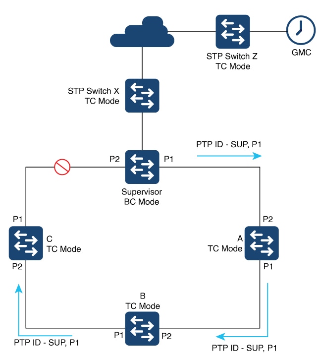
DLR ring connected to spanning tree protocol topology:
Figure 2. DLR ring connected to STP
The preceding diagram shows a single DLR ring used with the Spanning Tree Protocol (STP), with the GMC off the ring. The supervisor
operates in BC mode, and the ring nodes and STP switches operate in TC mode.
When operating as a boundary clock (BC), all TCs and ordinary clocks view the supervisor as the PTP parent—specifically, the
parent and the port number that transmits the PTP messages. In the diagram, the PTP messages are sent from Port 1. TCs and
ordinary clocks use the PTP ID to recognize the PTP parent based on the PTP clock ID of the supervisor, the port number (for
example, P1), and other attributes. All devices are synchronized to the PTP parent based on messages transmitted from P1.
When a fault occurs in the ring, the supervisor recognizes the fault and opens P2. This action allows all traffic to use that
port, enabling the topology to reconverge and restoring connectivity to devices. The supervisor sends PTP messages with the
port number set to P2 instead of P1. The change causes the ordinary clocks (the end devices) to perceive a change of the PTP
parent. End devices may resynchronize with the new PTP parent, and this transition can be disruptive.
Configure the DLR supervisor node in TC mode with support for multiple VLANs to overcome this limitation. Doing so would allow
the use of multiple VLANs while maintaining a single time source on the ring. Because all nodes in the DLR ring are in TC
mode, the parent ID and parent port number do not change when a failure occurs in the ring.
Restrictions for multiple VLAN support and PTP over DLR
Multiple VLAN support with TC restrictions
Multiple VLAN support with TC has these restrictions:
This feature is supported only on Cisco Catalyst IE3400 Rugged Series Switches and Cisco Catalyst IE3400 Heavy Duty Series
Switches.
DLR is the only Layer 2 redundancy protocol supported.
These Layer 2 protocols have not been validated with multi-VLAN TC: REP, Spanning Tree, MRP, PRP, HSR.
PTP mode restrictions on DLR nodes
Only these PTP modes are allowed on DLR primary and backup supervisor or gateway nodes:
Boundary clock
Transparent clock—multiple VLAN
Transparent clock mode (without multiple VLAN support) is not allowed on DLR primary and backup supervisor or gateway nodes.
Transparent clock mode (without multiple VLAN support) can be configured on DLR beacon nodes.
PTP over DLR is not supported for PTP power profiles.
PTP packet processing is restricted exclusively to Layer 3 packets across the DLR ring. You must prevent any leakage of Layer
2 PTP packets into the DLR ring from external networks because such leakage could cause undesirable looping and MAC flapping.
Configuring PTP over DLR
Recommendation: prerequisites for configuring precision time protocol
Configure PTP and DLR. Then implement the configuration commands in this section.
For information about PTP, DLR, and configuration instructions, refer to the documentation on cisco.com.
PTP: See the chapter "Configuring Precision Time Protocol" in this guide.
DLR: See the chapter "Device Level Ring" in the Redundancy Protocol Configuration Guide, Cisco Catalyst IE3x00 and IE3100
Rugged, IE3400 Heavy Duty, and ESS3300 Series Switches.
Set PTP transparent clock mode
This task configures PTP transparent clock mode on the switch with multi-VLAN support to enable precise time protocol functionality
across multiple VLANs.
Use this procedure to enable PTP transparent clock mode with multi-VLAN support on the switch to achieve precise time synchronization
across network segments.
Procedure
Step 1
Use the configure terminal command to enter global configuration mode.
Example:
Device# configure terminal
Step 2
Use the ptp mode e2etransparent multiple-vlan command to configure PTP transparent clock mode with multi-VLAN support.
Use the ptp vlan vlan-id command to configure the VLAN used to transmit and receive PTP packets on the trunk port.
Example:
Device(config-if)# ptp vlan 20
Step 8
Use the end command to return to privileged EXEC mode.
Example:
Device(config-if)# end
Show CLI commands
This reference lists the show commands that you can use for PTP and examples of their output.
show PTP clock
switch#show ptp clock
PTP CLOCK INFO
  PTP Device Type: End to End transparent clock - Multiple Vlan
  PTP Device Profile: Default Profile
  Clock Identity: 0x68:C8:EB:FF:FE:0:25:C0
  Clock Domain: 0
  Number of PTP ports: 10
  Time Transfer: Linear Filter
  Offset From Master(ns): 0
  Mean Path Delay(ns): 0
  TTL Value: 1
  DSCP Value for Event Messages: 59
  DSCP Value for General Messages: 47
  Delay Mechanism: End to End
  Local clock time: 21:38:35 UTC Mar 21 2023
switch#show ptp port gigabitEthernet 1/1
PTP PORT DATASET: GigabitEthernet1/5
Port identity: clock identity: 0xC:75:BD:FF:FE:C8:66:80
Port identity: port number: 1
PTP version: 2
Port state FAULTY: FALSE
Sync fault limit: 500000
Port PTP VLAN Id: 200
show PTP port gigabitEthernet 2/3
switch#show ptp port gigabitEthernet 2/3
 PTP PORT DATASET: GigabitEthernet2/3
  Port identity: clock identity: 0xC:75:BD:FF:FE:C8:66:80
  Port identity: port number: 13
  PTP version: 2
  Port state FAULTY: FALSE
  Sync fault limit: 500000
  Port VLAN Id: 20
  Rogue master block: False
show run int gigabitEthernet 2/3
switch#show run int gigabitEthernet 2/3
Building configuration...

Current configuration : 157 bytes
!
interface GigabitEthernet2/3
 switchport trunk native vlan 10
 switchport trunk allowed vlan 10,20,30
 switchport mode trunk
 ptp vlan 20
 dlr ring 1
end
Feature history for changing VLANs with PTP transparent clock
This table provides release and related information for features explained in this chapter. These features are available on
all releases subsequent to the one they were introduced in, unless noted otherwise.
Release
Feature
Feature information
Cisco IOS XE 17.13.1
Multiple VLAN selection with PTP transparent clock (TC)
Beginning in this release, you can change VLANs when using a Precision Time Protocol (PTP) TC. This feature is documented
for use with the Device Level Ring (DLR) protocol.


 Feedback