H-VPLS
The H-VPLS N-PE Redundancy for MPLS Access feature enables two network provider edge (N-PE) devices to provide failover services to a user provider edge (U-PE) device in a hierarchical virtual private LAN service (H-VPLS). Redundant N-PE devices increase stability and reliability by protecting against link and node failures. If a failure occurs in the network that disables one N-PE device from transmitting data, the other N-PE device takes over.
|
Feature name |
Release information |
Feature description |
|---|---|---|
|
H-VPLS N-PE Redundancy for MPLS Access |
Release 17.18.2 |
This feature enables a U‑PE to connect to two N‑PEs using active/backup pseudowires, delivering rapid switchover on link or node failure without service reconfiguration. |
Prerequisites for H-VPLS
-
Configure your H-VPLS network.
-
Enable the MPLS Traffic Engineering-Fast Reroute feature in the MPLS core to improve convergence.
-
Enable the L2VPN Pseudowire Redundancy feature on the U-PE devices for MPLS access.
Restrictions for H-VPLS
-
You cannot use this feature with the VPLS Autodiscovery feature on pseudowires that connect to U-PE devices. When you create the virtual private LAN service (VPLS), manually create the virtual forwarding interface (VFI).
-
You cannot configure more than one pseudowire to carry the bridge protocol data unit (BPDU) information between the network provider edge (N-PE) devices.
-
You cannot configure a local loopback address as a neighbor when you configure the H-VPLS N-PE Redundancy feature on N-PE devices.
-
Only two N-PE devices can be connected to each U-PE device.
H-VPLS N-PE redundancy with MPLS access based on pseudowire redundancy
For H-VPLS Redundancy with MPLS Access, the MPLS network uses redundant pseudowires. These pseudowires connect the MPLS network to N-PE devices in the VPLS core.
As shown in the figure, a primary pseudowire carries data between the U-PE and N-PE devices. If the U-PE path fails, a backup pseudowire and redundant N-PE device activate to continue data transport.
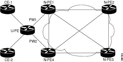
Configuration of H-VPLS N-PE Redundancy for MPLS Access
Specify the devices in the layer 2 VPN VFI
Before you begin
Ensure that the device is in configuration mode.
Procedure
|
Step 1 |
Use the l2vpn vfi context name command to establish a L2VPN VFI between two or more separate networks, and enter L2VFI configuration mode. Example: |
|
Step 2 |
Use the vpn id vpn id command to set a VPN ID on the VPLS instance. Example:
|
|
Step 3 |
Use the member ip address encapsulation mpls command to specify the device that forms a point-to-point L2VPN VFI connection. Example:
|
|
Step 4 |
Use the exit command to return to global configuration mode. Example: |
|
Step 5 |
Use the bridge domain bridge domain command to configure components on a bridge domain, and enter bridge-domain configuration mode. Example: |
|
Step 6 |
Use the member vfi vfi-name command to configure the VFI member in the bridge-domain. Example: |
|
Step 7 |
Use the member ip-address vc-id encapsulation mpls command to specify the device that forms a point-to-point L2VPN VFI connection. Example:
|
Specify the N-PE devices that form the layer 2 VPN cross connection with the U-PE
Before you begin
Ensure that the device is in configuration mode.
Procedure
|
Step 1 |
Use the interface type number command to specify the interface to configure, and enter interface configuration mode. Example: |
|
Step 2 |
Use the service instance id ethernet command to configure an ethernet service instance on the interface, and enter ethernet service configuration mode. Example: |
|
Step 3 |
Use the encapsulation untagged command define the criteria to map tagged or untagged frame ingress on the interface to the appropriate service instance. Example: |
|
Step 4 |
Use the exit command to return to interface configuration mode. Example: |
|
Step 5 |
Use the exit command again to return to global configuration mode. Example: |
|
Step 6 |
Use the l2vpn xconnect context context-name to create a L2VPN cross connect context, and enter xconnect configuration mode. Example: |
|
Step 7 |
Use the member gigabitethernet interface-number [service-instance id] command to specify devices that form a L2VPN cross connect. Example:service-instance id : (Optional) Specifies the service instance identifier. |
|
Step 8 |
Use the member ip-address vc-id encapsulation mpls [group group-name [priority number] command to specify devices that form a L2VPN cross connect. Example:
|
Configuration Example for H-VPLS N-PE Redundancy for MPLS Access
Example of configuring H-VPLS N-PE redundancy for MPLS access
The figure displays a configuration for H-VPLS N-PE redundancy with MPLS access. There is no option to configure multihoming on access VPLS, so the xconnect command with priority is used on uPE1.
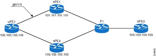
nPE1 Configuration
l2vpn vfi context VPLS-10
 vpn id 10
 member 102.102.102.102 encapsulation mpls
 member 103.103.103.103 encapsulation mpls
!
bridge-domain 10
 member vfi VPLS-10
 member 105.105.105.105 10 encapsulation mpls
nPE2 Configuration
l2vpn vfi context VPLS-10
 vpn id 10
 member 101.101.101.101 encapsulation mpls
 member 103.103.103.103 encapsulation mpls
!
bridge-domain 10
 member vfi VPLS-10
 member 105.105.105.105 10 encapsulation mpls
nPE3 Configuration
l2vpn vfi context VPLS-10
 vpn id 10
 member 101.101.101.101 encapsulation mpls
 member 102.102.102.102 encapsulation mpls
!
bridge-domain 10
 member vfi VPLS-10
uPE1 Configuration
interface GigabitEthernet0/1/0
 service instance 10 ethernet
 encapsulation dot1q 10
!
l2vpn xconnect context XC-10
 member GigabitEthernet0/1/0 service-instance 10
 member 101.101.101.101 10 encapsulation mpls group pwred priority 9
 member 102.102.102.102 10 encapsulation mpls group pwred priority 10
Verification
Use the show commands to verify that H-VPLS N-PE redundancy for MPLS access is configured successfully.
Sample Output on uPE1
Device# show xconnect peer 101.101.101.101 vcid 10

Legend:    XC ST=Xconnect State  S1=Segment1 State  S2=Segment2 State
  UP=Up       DN=Down            AD=Admin Down      IA=Inactive
  SB=Standby  HS=Hot Standby     RV=Recovering      NH=No Hardware

XC ST  Segment 1                         S1 Segment 2                         S2
------+---------------------------------+--+---------------------------------+--
UP pri   ac Gi0/1/0:10(Eth VLAN)         UP mpls 101.101.101.101:10           UP

Device# show xconnect peer 102.102.102.102 vcid 10

Legend:    XC ST=Xconnect State  S1=Segment1 State  S2=Segment2 State
  UP=Up       DN=Down            AD=Admin Down      IA=Inactive
  SB=Standby  HS=Hot Standby     RV=Recovering      NH=No Hardware

XC ST  Segment 1                         S1 Segment 2                         S2
------+---------------------------------+--+---------------------------------+--
IA pri   ac Gi0/1/0:10(Eth VLAN)         UP mpls 102.102.102.102:10           SB
Device#
Pseudowire types for H-VPLS
This section describes how the IR1101 router determines Pseudowire (PW) types automatically based on the interface configuration and how to manually override these types to ensure compatibility with far-end devices.
Understanding Pseudowire types
The IR1101 router supports two primary Pseudowire types for H-VPLS:
-
Type 4 (VLAN): Used for Ethernet VLAN interworking.
-
Type 5 (Ethernet): Used for raw Ethernet interworking.
Automatic PW type selection
The router automatically selects the PW type based on the type of interface where the xconnect is configured.
|
Interface Type |
Configuration Method |
Default PW Type |
|---|---|---|
| Layer 3 Interfaces (Onboard Gig, SP, SPMI, or 4S8I modules) | xconnect attached directly to the interface or sub-interface.
|
Type 5 (Ethernet) |
|
Layer 2 Interfaces (Onboard FastEthernet (Fa) or 4A2T modules) |
xconnect attached to a Switched Virtual Interface (SVI).
|
Type 4 (VLAN) |
Limitations
These are the limitations for selecting Pseudowire types:
-
Compatibility Check: Before configuring H-VPLS, verify the PW type used by the far-end device. If the IR1101 and the remote peer use mismatched types (one using Type 4 and the other Type 5), the connection will fail.
-
SVI Limitation: Configuring an
xconnecton an SVI automatically forces the router into Type 4 mode. -
FastEthernet Support: Onboard FastEthernet (Fa) interfaces are Layer 2 only and require an SVI for H-VPLS configuration.
-
Cisco IOS XE 26.1.1 Cosmetic Issue: In Cisco IOS XE 26.1.1 release, the configuration parser may incorrectly allow you to apply an
xconnectdirectly to a FastEthernet interface. This configuration is not supported and will not function. This issue is resolved in Cisco IOS XE 26.1.1 (or later releases). -
Always use an SVI for FastEthernet interfaces.
Overriding Pseudowire types
If the far-end device requires a specific PW type that does not match the IR1101 default, you can manually override the setting using an Layer 2 Virtual Private Network (L2VPN) cross-connect profile.
Here is an example of forcing Type 5 on an SVI:
Router(config-pw-class)# encapsulation mpls
Router(config-pw-class)# interworking ethernet
Router(config-pw-class)# exit
Router(config)# interface vlan 100
Router(config-if)# xconnect 10.1.1.1 123 pw-class PW_TYPE_5_PROFILE
Router(config-if)# end
To verify the current PW type use the show l2vpn atom vc [vcid/interface-id]detail command.
 Note |
You can look for the local interface type or PW type fields in the output to confirm if it is Type 4 or Type 5. |
 Feedback