Understand Templates on Catalyst Center
Available Languages
Introduction
This document describes Cisco Catalyst Center and experience with configuration templates for Three-Tier or Collapsed Core campus architectures.
Background Information
This document is intended for enterprise professionals with a foundational understanding of Cisco Catalyst Center and experience with configuration templates. It is particularly relevant for those who have worked or planning to work with Three-Tier or Collapsed Core campus architectures.
The main objective is to help readers implement and automate configuration and management solutions using templates within Cisco Catalyst Center. By presenting advanced insights, practical techniques, and real-world examples, this document serves as a practical resource for those looking to enhance their LAN infrastructure skills and optimize workflows through automation and template-based management.
Executive Summary
As enterprise networks continue to evolve, the need for scalable, consistent, and automated management has never been greater. Cisco Catalyst Center provides a centralized, intent-based platform that simplifies configuration, provisioning, and assurance across campus networks. This white paper explores how network professionals can leverage Cisco Catalyst Center’s CLI Template Editor and automation capabilities to streamline network operations, reduce configuration errors, and accelerate deployments across three-tier and collapsed core architectures. It details best practices for designing modular Jinja2-based templates, integrating automation into day-0 and day-N workflows, and achieving operational consistency across Core, Distribution, and Access layers. By adopting the strategies described in this document, you can transform traditional manual network management into an agile, standardized, and automation-driven model aligned with Cisco’s intent-based networking vision.
Challenges of Campus Networks
As campus networks evolve to meet the demands of modern organizations, they face several key challenges:
2a. Complexity in Network Management
Many network functions are still managed manually, increasing the risk of human error. This not only raises maintenance efforts but also strains IT resources, especially with static or limited budgets.
2b. Deployment and Automation Challenges
Onboarding new devices for both wired and wireless networks is often time-consuming and complex, leading to delays in deployment and increased administrative overhead.
2c. Software Image Management
Maintaining a consistent "golden image" across the network is challenging. Many networks end up with multiple operating systems for wired and wireless devices, leading to inefficiencies and management difficulties.
2d. Inconsistent Network Configurations
Variations in network configurations can result in compliance issues and operational inefficiencies, making it harder to maintain a reliable and secure network.
2e. Rising User Expectations
Users demand uninterrupted connectivity and seamless application experiences, regardless of their location or device. Meeting these expectations requires networks to be resilient, intelligent, and capable of adapting to real-time changes.
In addition to these challenges, modern LAN infrastructures face a variety of other complexities.
Simplifying Campus Networks with Cisco Catalyst Center
Cisco Catalyst Centre is a centralized network management solution for campus networks, supporting headquarters, branches, wired and wireless connections, and IT/OT environments. It offers flexible deployment options, including physical appliances, VMware ESXi servers, or AWS cloud. With comprehensive features, Catalyst Center simplifies operations, enhances performance, and strengthens security.
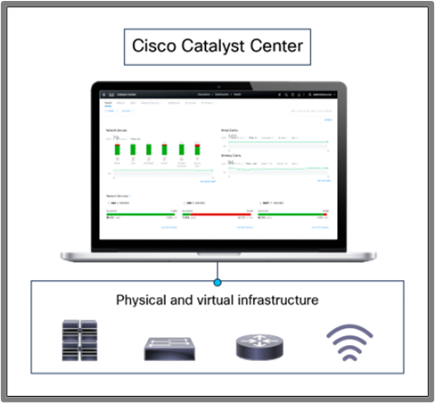 Figure 1: Managing infrastructure with Cisco Catalyst Center
Key Features and Benefits
Cisco Catalyst Center (CC) provides advanced features that streamline network management and automation:
Zero-Touch Provisioning (ZTP): Automates onboarding of devices, reducing manual effort and deployment time.
Software Image Management (SWIM): Ensures consistent software versions across devices with pre- and post-upgrade checks to prevent issues.
Intent-Based Automation: Simplifies deployments by translating network intent into device configurations for wired and wireless networks.
LAN Automation: Automates Layer 3 IP addressing and routing to create end-to-end topologies.
Wireless Network Automation: Features like Plug and Play (PnP) enable rapid provisioning of wireless access points.
Hierarchical Network Management: Allows site-specific profiles (example., SSIDs, RF parameters, VLANs) for consistent deployments across locations.
CLI Templates : The Catalyst Center Template Editor lets administrators easily create and manage CLI-based configuration templates, enabling consistent and efficient deployment across devices.
Assurance : Assurance allows to have centralized monitoring for managed devices via CC.
In addition to these features, Cisco Catalyst Center offers many more features that are beyond the scope of this document. This paper primarily focuses on designing CLI templates using Catalyst Center.
High-Level Overview of LAN Campus Architecture with Catalyst Center
Traditional LAN campus networks form the backbone of enterprise connectivity, ensuring reliable and scalable communication for wired and wireless devices. These networks are typically designed using either the 3-Tier Architecture or the Collapsed Core Architecture, depending on the size and complexity of the organization.
Three Tier Architecture
The Three-Tier Architecture is a foundational network design model that consists of the Core Layer, Distribution Layer, and Access Layer. This architecture provides scalability, high performance, and efficient traffic management. See the overview of each layer.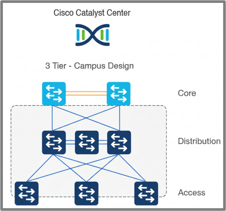 Figure 2: Three-Tier Campus Architecture
Core Layer
The Core Layer serves as the backbone of the network, delivering high-speed connectivity and scalability. Key configurations include northbound and southbound routing protocols (such as OSPF and BGP), route policies, downlink and uplink interface configurations, security hardening Etc
Distribution Layer
The Distribution Layer bridges the Core and Access layers, handling traffic aggregation, policy enforcement, and redundancy. Key configurations include HSRP/VRRP for redundancy, STP for loop prevention, Layer 2 and Layer 3 VLANs, uplink and downlink interface configurations, ACLs for security, and security hardening.
Access Layer
The Access Layer connects endpoints to the network, enabling secure and reliable access. Key configurations include access interface configuration, uplink interface configuration, Layer 2 VLANs, ACLs for restricting access to the device, and security hardening.
Collapsed Core Architecture
The Collapsed Core Architecture combines the Core and Distribution layers into a single layer, reducing complexity and cost while maintaining performance and scalability. This approach is well-suited for small to medium-sized networks where a separate Core Layer is not required. See the overview of the layers in this architecture.
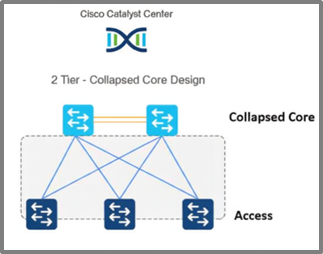 Figure 3: Collapsed Core Campus Architecture
Collapsed core Layer
The Collapsed Core Layer combines the functions of the Core and Distribution layers, providing backbone connectivity, traffic aggregation, and policy enforcement. Key configurations include northbound and southbound routing protocols (such as OSPF and BGP), route policies, downlink and uplink interface configurations, BFD for fault detection, inter-VLAN routing using SVIs, HSRP/VRRP for gateway redundancy, STP for loop prevention, and security hardening. By leveraging templates in Cisco Catalyst Center, these configurations can be automated, ensuring consistent and efficient deployments.
Access Layer
As previously described, the access Layer connects endpoints to the network, enabling secure and reliable access. Key configurations include access interface configuration, uplink interface configuration, Layer 2 VLANs, ACLs for restricting access to the device, and security hardening.
Template Design Consideration
This section outlines how to design templates in Cisco Catalyst Center for generating device configurations. The Template Editor streamlines provisioning by enabling the creation of reusable CLI templates and supporting the dynamic deployment of configurations tailored to your network. Catalyst Center supports two templating languages: Jinja2 and Velocity. These languages help in configuration management for devices.
Jinja is a popular, designer-friendly templating language primarily used with Python for generating dynamic content like HTML, XML, or other text-based formats. It allows embedding variables and control structures (like loops and conditionals) within templates to create dynamic output.
Apache Velocity is a Java-based templating engine that uses the Velocity Template Language (VTL) to enable dynamic content in various documents, including web pages, XML, or even source code. It merges data from Java objects with templates to produce the final output.
This document covers only Jinja2 templates.
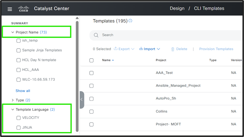 Figure 4: Cisco Catalyst Center Template Editor
In this document, we use Jinja2 due to its flexibility. Rather than an in-depth exploration of Jinja2, the focus is on practical application for template design. For more information on Jinja2 templating in Catalyst Center, please refer to the link:
https://ciscolearning.github.io/cisco-learning-codelabs/posts/cat-center-j2-part-1/#0
Before diving into template design strategies for a Cisco campus network, it is important to utilize the key best practices to ensure efficiency and manageability when working with templates.
Template structure and best practices / Guideline for best strategy
When automating the configuration of network devices using Cisco Catalyst Center, it is essential to adopt structured strategies and best practices. These steps help ensure consistency, scalability, and ease of management across your network infrastructure.
Divide Configuration by Device Role
Start by categorizing devices according to their role in the network topology. Common roles include:
Core
Distribution
Access
Example: A device functioning as a Core switch mustit have different configuration requirements compared to an Access switch.
Compartmentalize Configuration into Modular Blocks
Within each device role, break down the configuration into modular blocks by grouping similar features or configurations together. This modular approach simplifies automation, troubleshooting, and future updates.
Examples for a Core Device:
OSPF Configuration Block
BGP Configuration Block
QoS Policies Block
Identify Role-Agnostic Configuration Blocks
Some configuration blocks apply universally across all device roles. Identifying and standardizing these blocks ensures best practices and consistency throughout the network.
Common Role-Agnostic Configuration Blocks:
Base Configuration: Hostname, login banners
Management Protocols: DHCP, DNS, NTP, SNMP
Access Policies: Standard security configurations
These blocks can be reused for Core, Distribution, and Access devices, streamlining the automation process.
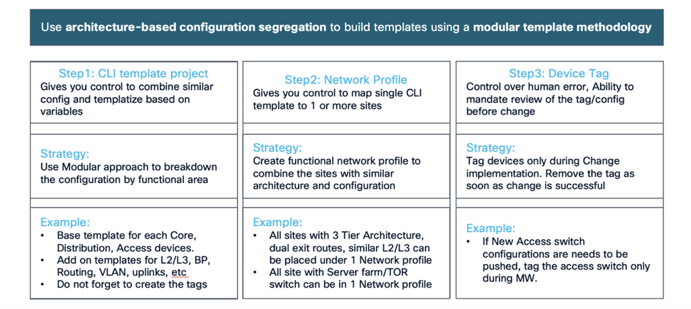 Figure 1: Best Practice with Example
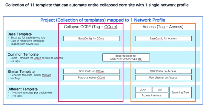 Figure 2: Collapsed Core template example
Best Practices for Working with Templates
Modular Template Design for Automated Configuration
When automating device configurations in Cisco Catalyst Center, avoid embedding all configurations into a single, monolithic template. Instead, adopt a modular approach:
Create a base template that references smaller, purpose-specific templates (modules):
Break down configuration into logical modules (example., interface settings, routing protocols, security features).
This structure makes updates more efficient—changes to a specific module are automatically reflected wherever that module is used, significantly reducing errors and complexity.
Example: Modular Configuration for a Branch Device
Suppose you are automating the configuration for a branch device.
Base Template:
Includes references to module templates for key configuration areas.
Passes variables as needed to each module for customization.
Module Templates:
interface_settings: Manages interface configurations.
routing_protocols: Contains OSPF, EIGRP, or BGP settings.
security_features: Defines ACLs, firewall rules, or other security policies.
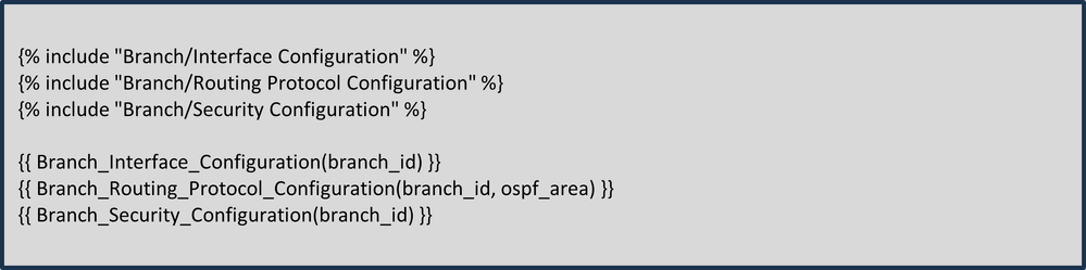 Base Template Structure Example:
With this structure, any changes to routing or security configurations only need to be made in their respective modules, and those changes are instantly reflected wherever the base template is used. This makes your configurations more manageable and consistent across all branch routers.
Here project name is Branch and 3 other different modules are defined under project. All of these are combined in base template.
Minimize Variables in the Template
Keep the number of variables in your template to a minimum, to reduce complexity and errors. Fewer variables simplify deployment, especially across large networks, making the process more efficient and consistent.
Using Device Tags for Templates
Leverage device tags in Cisco Catalyst Center, such as location, role, or site, to create dynamic and scalable Jinja2 templates. These tags enable conditional logic, ensuring the correct configurations are applied to the appropriate devices. This approach minimizes errors and simplifies template management across diverse network environments.
Hardcode Static Values Where Possible
Hardcoding static values can simplify templates and improve deployment efficiency. Common examples include IP addresses for DNS, NTP, or Syslog servers, which typically remain consistent across devices. Similarly, using standard VLAN IDs on access switches allows these values to be hardcoded, reducing variability and accelerating deployment.
Adopt a Two-Stage Approach: Day 0 and Day N Templates
When onboarding devices using services like Cisco Plug and Play, use a two-stage template strategy:
Day 0 Templates: Push basic configurations to ensure the device can communicate with the Cisco Catalyst Center.
Day N Templates: Deploy advanced features and configurations once the device is reachable.
Best practices enables efficient and scalable templates which simplify Cisco campus network deployments.
Whitespace Control in Jinja Template Macros
When creating templates using the Jinja language, it is essential to handle whitespace and newlines carefully, especially when rendering dynamic content within macros. Accumulated whitespace or unintended newlines can lead to formatting issues in the generated output, which must cause misinterpretation or errors in downstream processing. To address this, Jinja provides syntax for controlling whitespace: placing a minus sign (-) directly inside the delimiters ({{- ... -}} or {%- ... -%}) it strip any leading or trailing whitespace around the expression. For example, replacing {{item[1]}} with {{- item[1] -}} ensures that any extra spaces or newlines are removed when the macro is rendered. This practice is especially helpful when iterating through lists or generating configuration files, as shown in the template snippet. We recommend always applying whitespace control in such scenarios to maintain clean and predictable outputs.
Example (Recommended Usage):
{% for item in wildcard_list %}
{% if item[0] == prefix -%}
{{- item[1] -}}
{%- endif %}
{%- endfor %}
Three Tier Architecture
This whitepaper begins with developing templates for access switches through to core switches and outlines the requirements for each layer.
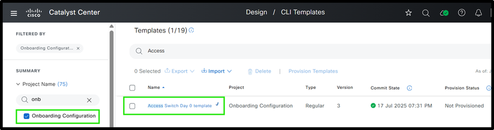
Access Layer Switches
Access switches are onboarded using Plug and Play and must require a Day 0 template. For more information about the Plug and Play process in Catalyst Center, please refer to the link :
As previously discussed, Catalyst Center supports both Velocity and Jinja2 templating languages. This document utilizes Jinja2 to illustrate template structure, due to its flexibility. Access layer switch configuration can be deployed using the Day-0 and Day-N template.
A basic Day 0 template can be structured, see Step 1:
Step 1 : Define Template
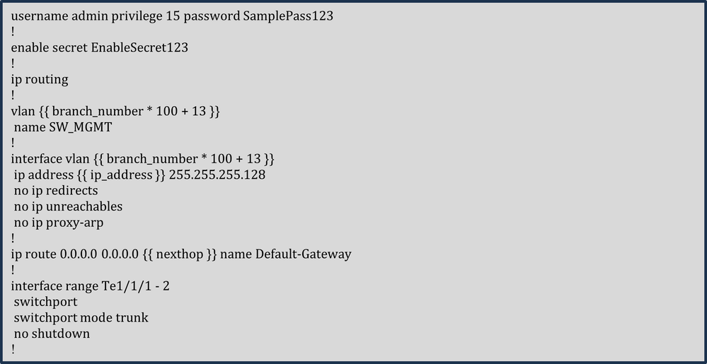 Step 1 : Define Template
The template simplifies configuration by hardcoding constants such as username, password, enable secret, and subnet mask, since all switches in a branch share the same management VLAN subnet mask. The management IP address, however, is unique for each switch and is defined as a variable. A comprehensive template structure must be provided in the Day N template, which utilizes this Day 0 template. In the Day N template, each feature of the access switch is managed by a dedicated module—for example, one module handles Layer 2 VLANs, separate modules manage uplink and downlink access interfaces, another module focuses on security hardening, and so on.
While consistent VLAN IDs are preferred, varying IDs can be generated dynamically using a formula based on the branch number (example., Branch 1 = VLAN 113, Branch 2 = VLAN 213). This makes the template reusable across branches. Similarly, the next-hop IP is a variable, as it must differ per branch depending on the connected distribution cluster.
Step 2 : Perform Simulation and provide variable
 Access Switch Day 0 Template Structure with Simulation Inputs and Outputs
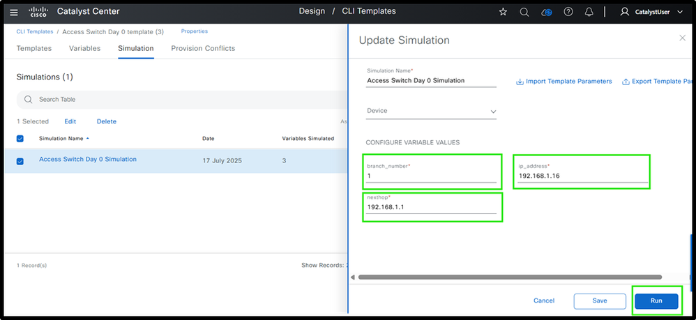 Ex. Simulation Inputs
It is always recommended to simulate the template before deployment. The screenshot shows the final configuration after entering the variables.
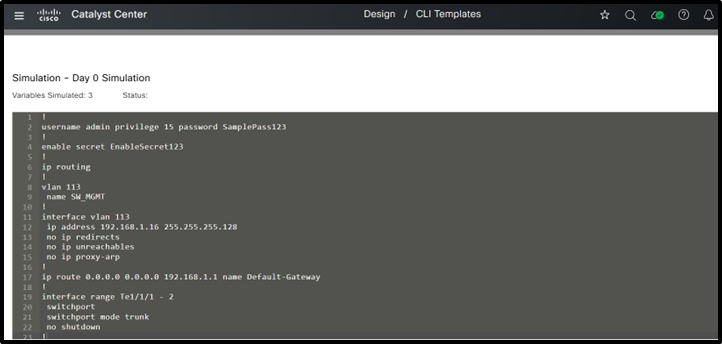 FInal Config after entering values
Now, let’s look at how to create a modular Day N template.
The access switch configuration can be divided into various modules, all of which can be combined within a base module. The base template for access switches is structured as shown.
Both the base template and its modules are created within a project named "Test" in Cisco Catalyst Center.
Step 1 : Define various Templates including Base template
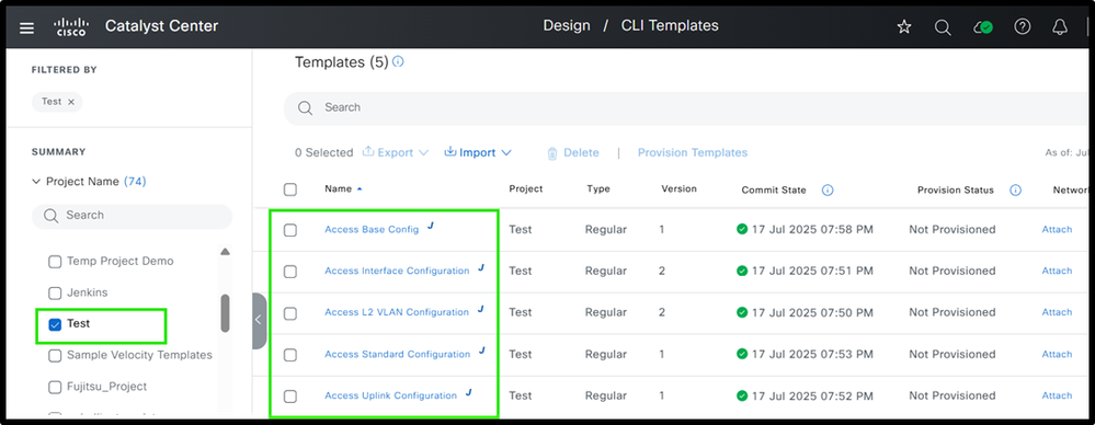 Access Switch Day N Template Structure
Step 2 : Define various modules
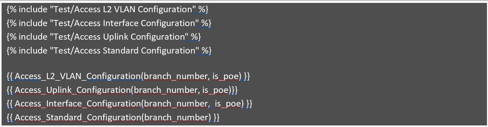
Access Base Config :
The screenshot shows an example of the base configuration.
 Access Base Config
This modular configuration template includes four parts: VLAN configuration, uplink interface configuration, access interface configuration, and standard configuration. It uses only two variables: branch_number and is_poe, keeping it simple and easy to manage.
The branch_number calculates branch-specific VLAN IDs, as shown in the Day 0 template, and is_poe determines if the access switch is a PoE or non-PoE switch. These variables are provided during provisioning and passed to the modules to create the correct configurations, reducing effort and improving efficiency.
Now, let’s review each module to see how they contribute to generating specific parts of the overall configuration.
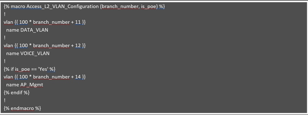
Access L2 VLAN Configuration
 Access L2 VLAN Configuration
This module creates VLANs based on the branch number, as previously explained. Data and Voice VLANs are created on all switches, whether they support PoE or not. The AP Management VLAN (example., 114 for branch 1) is only created if is_poe is set to "Yes," meaning the switch supports PoE. If is_poe is "No," the AP Management VLAN is skipped since non-PoE switches can not support access points. This is managed using an if condition.
 Access Interface Configuration
This module handles the access interface configuration and utiizes the same approach as the PoE switch described earlier. If the is_poe variable is "Yes," meaning the switch is a PoE switch, the first six ports (1-6) must be configured with the AP management VLAN. Otherwise, the first six ports must be set as user access ports.
Assuming the switch is a 24-port model, the remaining ports (7-24) always get configured as user access ports, regardless of whether the switch is PoE or not.
The interface range has been standardized and is no longer taken as an input variable, which is considered a best practice to minimize the number of variables in the template. Additionally, the module includes a macro named common_access_settings, which minimizes template size by consolidating repeated configurations. This macro is simply called within the interface settings, avoiding the need to specify them multiple times.

Note: This template applies the same description to all access interfaces. If unique descriptions are needed for each interface, it’s recommended to push them using separate Python scripts or similar automation tools.
Review the module that generates configurations for uplink interfaces.
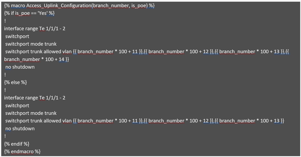 Access Uplink Configuration
This module generates the configuration for uplink interfaces and handles VLAN pruning. If the switch supports PoE, the AP Management VLAN is included in the list of allowed VLANs; otherwise, it is excluded. This logic is managed using if condition in the code, as described earlier.
Review the final module, which demonstrates standard configurations, including best practices and security hardening.

Caution: Note that this is for illustrative purposes only and must not be used as a reference for actual network setups, as configurations can vary based on specific requirements
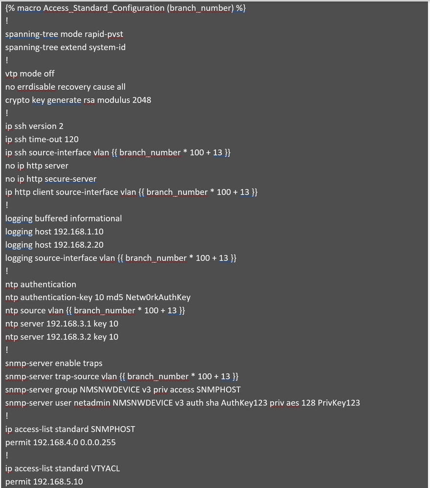 Part 1: Access Standard Configuration
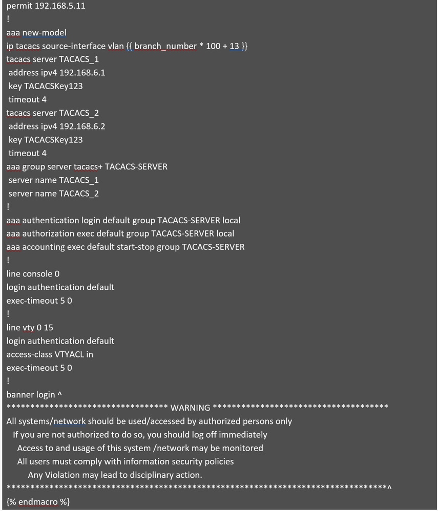 Part 2: Access Standard Configuration
This module generates a standard configuration that incorporates best practices, security hardening, and key features for secure device management. Most values are hardcoded for consistency across branches, except branch_number, which is used to calculate the management VLAN for switches in each branch and serves as the source interface for several configurations.
Step 3 : Perform a simulation before configuring the switches. Only the base configuration must be simulated.
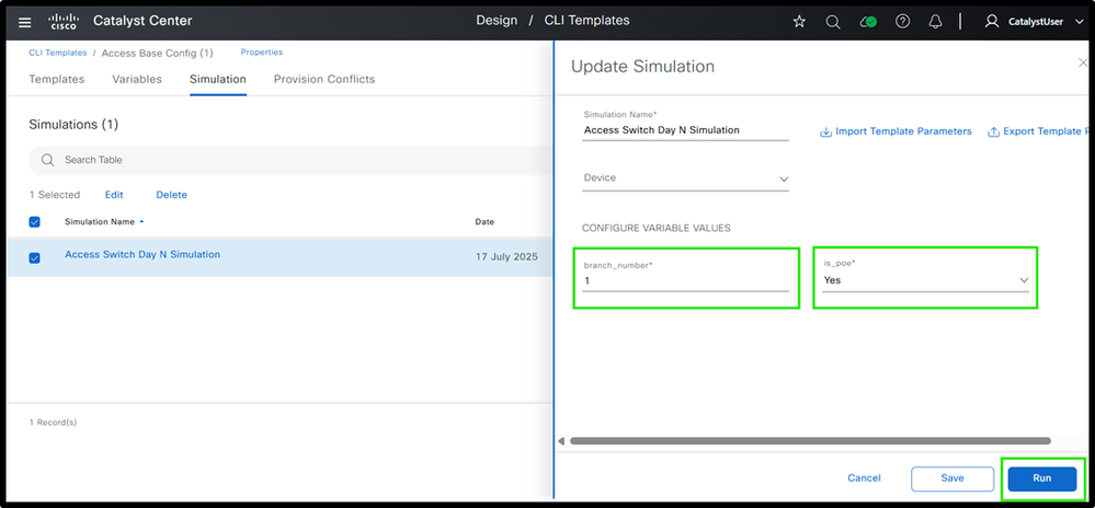 Figure 7: Access Switch Day N Template Simulation Inputs and Outputs
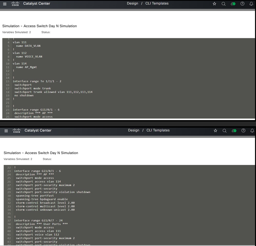 Simulation
This is how templates can be used at the access layer to generate configurations.
Now, let’s take a look at the distribution layer devices to see how templating can be applied to them.
Distribution Layer Switches
Now to design a modular template for distribution switches. The base template and its modules are part of the 'Distribution Switch' project in Cisco Catalyst Center.
Step 1 : Distribution Switch Template Structure
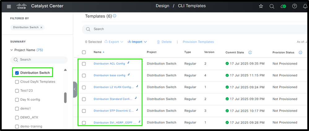 Ex. Distribution Templates
Step2 : Define each module
The base configuration provided defines each and all modules are referenced.
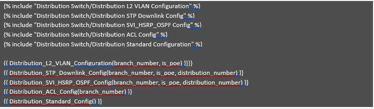 Ex. Distribution Base Template Modules
Similar to access switches, all templates are created within the 'Distribution Switch' project and referenced in the base template. While some templates are identical to those used for access switches, this section explains the differences specific to distribution switches. The module "Distribution L2 VLAN Configuration" is identical to the one described earlier for access switches. Please check Access L2 VLAN Configuration module which provides this information. It generates the required VLANs based on the input values provided for the variables.
Now review the "Distribution STP Downlink Config" module, which handles the generation of spanning tree and uplink configurations for distribution switches.
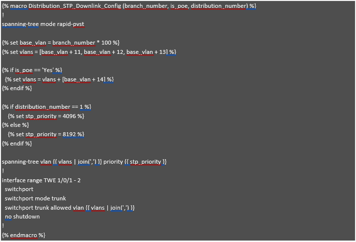 Distribution STP Downlink Config
Here Jinja2 macro functionality is being used , which is referenced in based module. So this structure helps in building modular approach.
This module configures Spanning Tree Protocol (STP) and downlink interfaces based on the "branch_number" and whether the switch is PoE-enabled. The "branch_number" variable is used to generate unique base VLANs for each branch, ensuring distinct VLANs, similar to the approach already highlighted for access switches. If the switch is PoE-enabled ("is_poe" == 'Yes'), an additional VLAN, such as the AP Management VLAN, is added to the list. The "distribution_number" variable determines the STP priority, setting 4096 for Distribution 1 (making it the preferred root bridge) and 8192 for secondary distribution switches. Finally, the appropriate VLANs are applied to the trunk interface, ensuring that only the relevant VLANs are allowed based on whether the switch is PoE-enabled.
Now review the "Distribution SVI_HSRP_OSPF Config" module, which focuses on the setup of SVIs, HSRP, and OSPF for efficient network routing and redundancy.
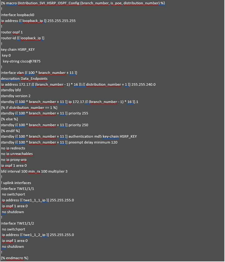 Distribution SVI_HSRP_OSPF Config
This module, Distribution_SVI_HSRP_OSPF_Config, helps configure SVIs, HSRP, OSPF, and uplink interfaces for distribution switches. In this example, we are focusing on the SVI for data subnets, but the same method can be used for other SVIs like voice or management.
If the IP address planning for data subnets is already done, the IP addresses can be calculated automatically for each SVI based on the branch_number and distribution_number variables. For example, if branch 1 has the subnet 172.17.0.0/20, branch 2 has 172.17.16.0/20, and branch 3 has 172.17.32.0/20, the gateway IP is 172.17.x.1 (where x is the branch number). The second IP for the first distribution switch is 172.17.x.2, and the third IP for the second distribution switch is 172.17.x.3. This way, the IP addresses are automatically calculated, reducing errors and simplifying the process.
The loopback interface is assigned an IP from the variable loopback_ip, which serves as the OSPF router ID to ensure stable and consistent routing across the network. In the OSPF configuration, this loopback IP is used as the router ID, and the relevant interfaces are added to OSPF area 0. For HSRP, priority values are set: 255 for the first distribution switch and 250 for the second, ensuring proper failover. Additionally, HSRP authentication is configured using a key chain (HSRP_KEY) to enhance security.
To keep the configuration clean and manageable, some values are hardcoded. For instance, the subnet mask (255.255.240.0) and certain HSRP settings (like version and BFD) are the same across all branches, reducing the number of variables. This makes the configuration simpler, easier to apply, and less likely to have mistakes. Lastly, the uplink interfaces are configured with IPs and added to OSPF area 0 for proper routing between switches. This approach makes the configuration process easier to manage and less prone to errors, while also being flexible for different branches.
Now review the "Distribution ACL Config" module, which provides segmentation at the distribution layer.
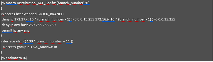 Distribution ACL Config
This module demonstrates segmentation at the distribution layer using a Jinja2 template. It utilizes the branch_number variable to dynamically calculate subnet addresses, enabling automated and scalable ACL configurations. For each branch, the ACL blocks communication between subnet 1 (172.17.X.0) and subnet 2 (172.16.X.0) by denying IP traffic between these ranges. It also denies traffic to the multicast address 239.255.255.250, while permitting all other traffic. The VLAN interface is assigned dynamically based on the branch number, and the ACL is applied inbound on that interface. This automated approach ensures effective per-branch segmentation, reduces manual configuration errors, and simplifies network policy enforcement.
Finally, the last module, "Distribution Standard Configuration," is nearly identical to the one described in the Access Standard Configuration module (please refer to that section for details). It includes best practices, security hardening, and key features for secure device management. The only difference lies in the source interface: in the Access Switch template, it is defined as VLAN {{ branch_number * 100 + 13 }}, whereas in the Distribution Switch configuration, it can be hardcoded as Loopback0.
Step 3: Perform Simulation before deploying the configuration.
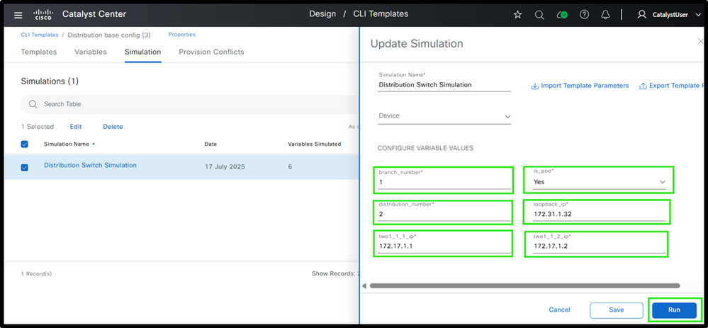 (1) Distribution Switch Template Simulation Inputs and Outputs
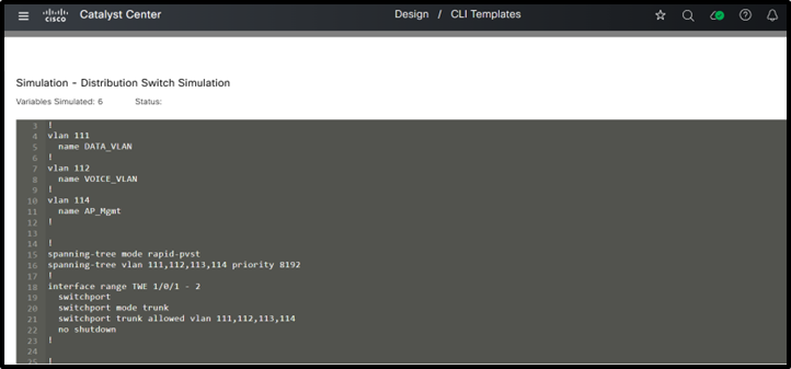 (2) Distribution Switch Template Simulation Inputs and Outputs
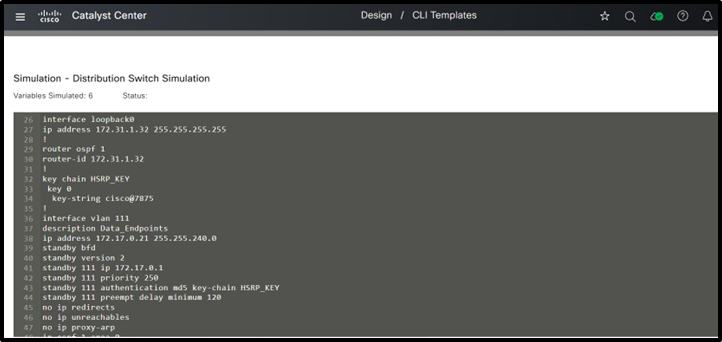 (3) Distribution Switch Template Simulation Inputs and Outputs
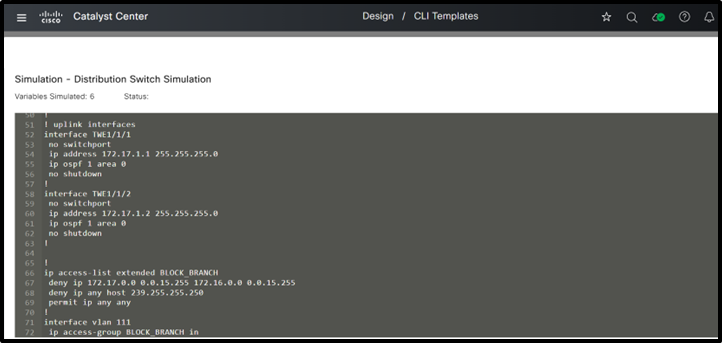 (4) Distribution Switch Template Simulation Inputs and Outputs
This is how templates can be used at the distribution layer to generate configurations. Now, let’s take a look at the core layer devices to see how templating can be applied there.
Core Layer Switches
Now design a modular template for core switches. The base template and its modules are part of the 'Core Switch' project in Cisco Catalyst Center. See the base template in step 1.
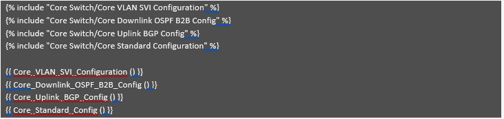
Step 1 : Define various core switch Structure
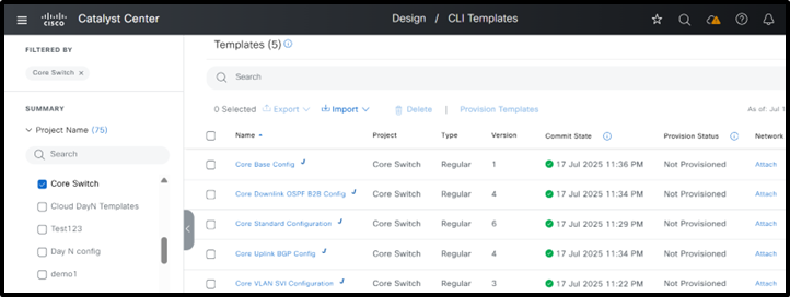 Core Switch Template Structure
Step 2 : Define various modules
 Core Base Config
Most core switch configurations are similar across all branches, so common values can be hardcoded. Usually, only the IP addresses change, and these can be set using variables. Since each branch typically has only two core switches, managing these variables is straightforward. Even if some branches have more core switches, their number is still less than the number of access or distribution switches. That’s why as a best practice, it’s more important to minimize variables for access and distribution switches, as they are used in larger numbers and having too many variables can make configuration more time-consuming.
Now begin with the first module: "Core VLAN SVI Configuration." In this example, the core switches are positioned behind a firewall and must establish eBGP peering with it. This module is responsible for generating the VLANs and corresponding SVIs required for the eBGP peering and OSPF neighborship. The firewall is assumed to operate in an active/standby configuration.
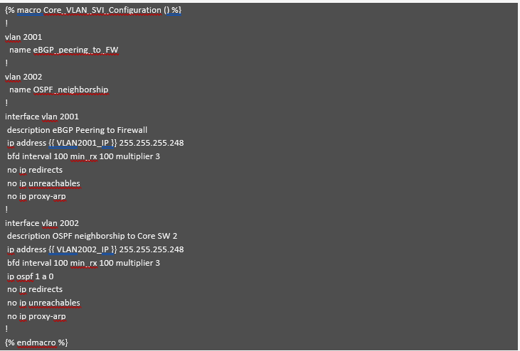 Core VLAN SVI Configuration
This module, as explained earlier, creates the required VLANs and associated SVIs for establishing OSPF and BGP neighbor relationships. All parameters, except for the SVI IP addresses, are hardcoded—including the subnet mask if it aligns with the IP addressing plan. This method helps limit variables and reduces the potential for configuration errors.
Now, let’s review the "Core Downlink OSPF B2B Config" module, which generates configurations for downlink interfaces, OSPF, and back-to-back links between Core Switch 1 and Core Switch 2.
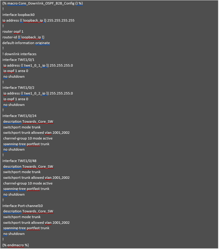 Core Downlink OSPF B2B Config
Similar to the previous module, most values in this module are hardcoded to minimize the number of variables. Only the IP addresses for loopback and downlink interfaces are variable. Additionally, the back-to-back port channels and VLANs are standardized across different branches.
Now, let’s review the "Core Uplink BGP Config" module, which generates BGP configurations and manages uplinks connected to the firewalls.
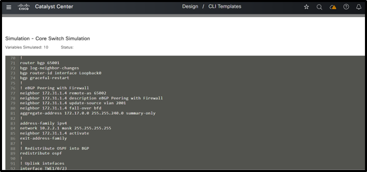
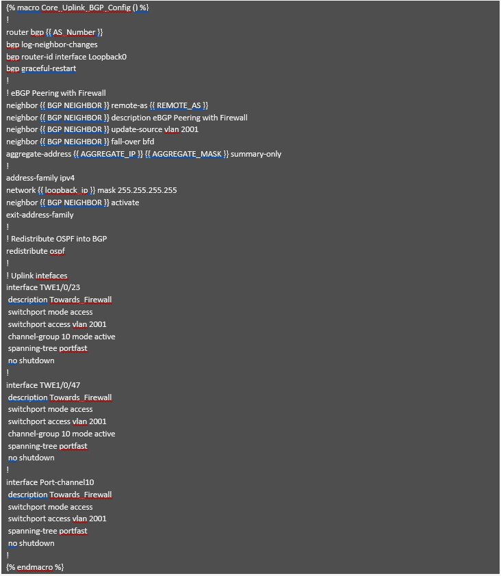 Core Uplink BGP Config
This module generates the BGP configuration needed to establish an eBGP neighbor relationship with the firewall. As shown above, most values are hardcoded since they remain consistent across different branches. Only the IP addresses and AS numbers, which can vary for each branch, are taken as input variables and used to generate the necessary configuration. Most other settings have been standardized to minimize the number of variables. The uplink interfaces connected to the firewall are specified along with the VLAN used for eBGP neighborship, which was generated by the previous module.
Finally, the last module, "Core Standard Configuration," is almost identical to the one described in the Access Standard Configuration (refer to that section for more details). It includes best practices, security hardening, and key features for secure device management. Consistent with the distribution switch configuration, the source interface can be set to loopback0 in this module as well, and this value can be hardcoded.
Step 3 : Perform Simulation
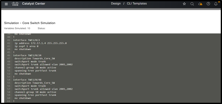
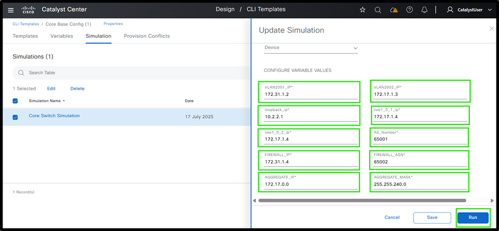 (1) Core Switch Template Simulation Inputs and Outputs
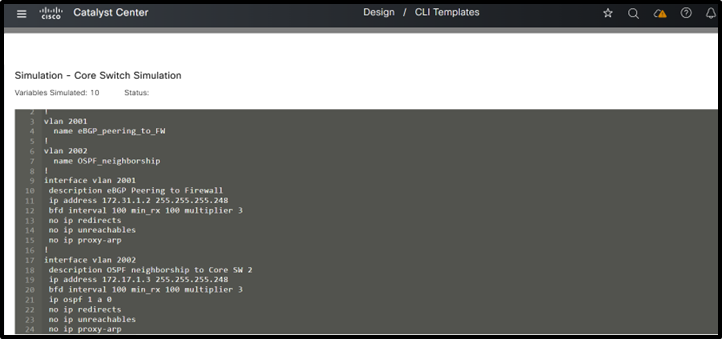 (2) Core Switch Template Simulation Inputs and Outputs
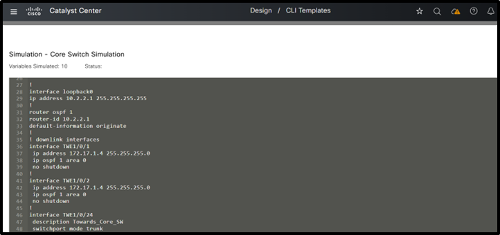 (3) Core Switch Template Simulation Inputs and Outputs
 (4) Core Switch Template Simulation Inputs and Outputs
 (5) Core Switch Template Simulation Inputs and Outputs
This completes the detailed explanation of designing templates for the Three-Tier Architecture, outlining both the structure and configuration of each module.
All of these module utilize the best practices explained earlier.
Note: When designing templates for a collapsed core architecture, please refer to the explanations provided for the Three-Tier architecture. The template structure remain the same; however, features that were previously implemented separately at the core and distribution layers are now combined at the collapsed core layer. The same modular template approach can be used here as well, by creating a base template and referencing the relevant modules within it.
Summary
The traditional 3-tier campus architecture often relies on extensive manual configuration across the core, distribution, and access layers. This approach is not only time-consuming but also prone to human error. The absence of automation and centralized management significantly increases operational overhead, making it difficult to scale and manage modern, dynamic campus networks effectively. Through Catalyst Center CLI template feature configurations can be automated for the traditional LAN networks. It is important to utilize the modular approach while provisioning the devices. Modules can be based upon the various features used at different layers. And then finally bind all these modules to base module.
Call to Action
We invite organizations to adopt the modular template methodology presented in this white paper as a best practice for standardizing switch configurations and optimizing network operations across both three-tier and collapsed core architectures.
- By implementing modular templates, network teams can:
- Improve operational efficiency through consistent, repeatable configuration practices.
- Minimize human error and reduce troubleshooting time.
- Achieve greater scalability to support growth and evolving business needs.
- Ensure configuration consistency across diverse environments.
This approach not only streamlines day-to-day management, but also enables faster deployments, simplifies update cycles, and enhances alignment with security and compliance requirements. Adopting modular templates positions your network for agility, resilience, and long-term success in an ever-changing IT landscape.
For practical demonstrations, learn more about templates , please see YouTube series
1 How to create and manage templates in Catalyst Center
2 How to Use System Bind Variables in CLI Templates in Catalyst Center
Authors
Naveen Kumar, Customer Delivery Architect, Cisco Customer Experience
Risabh Mishra, Consulting Engineer, Cisco Customer Experience
Revision History
| Revision | Publish Date | Comments |
|---|---|---|
1.0 |
08-Apr-2026
|
Initial Release |
 Feedback
Contact Cisco
- Open a Support Case

- (Requires a Cisco Service Contract)