Cisco Catalyst Center AI-Enhanced RRM Deployment Guide
Available Languages
Bias-Free Language
The documentation set for this product strives to use bias-free language. For the purposes of this documentation set, bias-free is defined as language that does not imply discrimination based on age, disability, gender, racial identity, ethnic identity, sexual orientation, socioeconomic status, and intersectionality. Exceptions may be present in the documentation due to language that is hardcoded in the user interfaces of the product software, language used based on RFP documentation, or language that is used by a referenced third-party product. Learn more about how Cisco is using Inclusive Language.
- US/Canada 800-553-2447
- Worldwide Support Phone Numbers
- All Tools
 Feedback
 Feedback
Overview of Cisco Catalyst Center AI-Enhanced RRM
Day-0 configuration: Setting up Cisco Catalyst Center to use AI-Enhanced RRM
Day-1 AI-Enhanced RRM features and use cases
Day N: Making changes to AI RF Profile
Disable AI-Enhanced RRM: Unassign AI RF Profile
Overview of Cisco Catalyst Center AI-Enhanced RRM
AI-Enhanced RRM is the next evolution of Cisco’s award-winning RRM (Radio Resource Management). RRM was originally introduced with Cisco AireOS and Aironet in 2005 and managed the complexities of RF from Wi-Fi 1-6 and now Wi-Fi 6E. RRM has fluidly grown to include innovative algorithms like Flexible Radio Architecture (FRA), and Dynamic Bandwidth Selection (DBS) to the traditional algorithms of Dynamic Channel Assignment (DCA) Transmit Power Control (TPC).
On a Cisco Catalyst C9800, traditional RRM runs as a process. Cisco RRM manages the RF Group (the components making up the RF Network) based on dynamic measurements between every AP and its neighbors. This information is stored in a local database on the RF Group Leader controller. At runtime, RRM draws on the last 10 minutes of collected data and gently optimizes based on the current network conditions. Cisco RRM has proven to be extremely effective and trustworthy over the years. Configured correctly for the type of RF network coverage desired (Capacity vs. Coverage), it can adapt to almost any size or deployment density. In Wi-Fi, RF Conditions can dynamically change with different network loads, numbers of devices, and number of users in the environment. RRM has continued to measure up well to this task, with caveats that require some learning for the environment being tuned.
Enter Cisco’s AI-Enhanced RRM. AI-Enhanced RRM integrates the power of Artificial Intelligence and Machine Learning (AI, ML) into the reliable and trusted Cisco RRM Product family algorithms in the Cloud. AI-Enhanced RRM is coordinated through Cisco’s Catalyst Center (on-prem appliance) as a service. Existing Cisco Catalyst C9800 RRM sites can seamlessly transition to an intelligent centralized service. As with other Cisco Catalyst Center services, AI-Enhanced RRM brings a host of new features with it. The Cisco Catalyst Center RRM Control Center allows administrators to quickly assess the health and performance of the RF coverage from the enterprise level all the way down to a single site or building level.
Cisco AI-Enhanced RRM is different as it allows the analysis of historical dynamic RF data over time. The ability to evaluate complex RF data often comes down to being able to factor in local knowledge of “Normal” against the currently displayed data. “Normal” can and does vary from site to site based on the equipment choices and architectural design vs. Client density.
After an initial learning period, the Cisco AI Analytics Cloud will begin to provide insights into the performance and tuning of the RF network. Insights provide granular guidance on:
● Performance against SLAs
● The effectiveness of present settings/configurations
● The Quality of the coverage
Together, the AI-Enhanced RRM Algorithms with the power of the Cisco AI Analytics Cloud and Cisco’s Catalyst Center take Wi-Fi RF Management to an unprecedented level that correlates 24x7 observations from the network and the client devices themselves and applies 20+ years of Cisco RF Excellence to drive exceptional user experiences into the future.
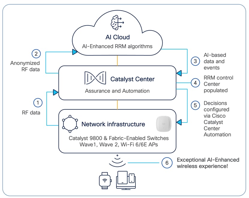
Cisco AI-Enhanced RRM Data Flows and Functional Components
Cisco AI-Enhanced RRM operates as a distributed RRM service. RF telemetry is collected from the Cisco Access Points by the Catalyst WLC and passed through the Cisco Catalyst Center to the Cisco AI Analytics Cloud, where the data is stored. The RRM Algorithms run against this telemetry data stored in the cloud. AI analyzes the solutions and returns any configuration change information to the Cisco Catalyst Center. Catalyst Center maintains the control connection with the enrolled Cisco C9800 and returns any individual AP configuration changes to the APs. The Cisco AI Analytic Cloud operates like the WLC RF Group Leader on the controller today but with much more storage, compute power, and intelligent analysis.
Network-wide holistic Optimizations are performed by the RRM Resource Analytics Engine, which focuses on dynamically created groups of radios (Clusters) to optimize local performance without falling victim to the pitfalls of greedy optimizations leading to cascading network changes and potential network disruptions. Algorithms for Dynamic Channel Change (DCA), Transmit Power Control (TPC), Flexible Radio Assignment (FRA) and Dynamic Bandwidth Selection (DBS) are some examples of the types of optimizations performed. These algorithms are latency-tolerant and blend well with Catalyst Center Eco System management.
The RRM Edge Compute Engine focuses on latency-sensitive and client-specific optimizations. Examples of these types of services include Optimized Roaming, DFS Optimizations, Coverage Hole Detection/Mitigation, EDRRM, and Dynamic DFS amongst others. These functions are maintained on the local WLC, the telemetry data is sent to AI-Cloud where AI-Enhanced RRM algorithms run. This analysis will provide optimization guidance and insights to the RRM Control Center to help Admins further optimize the configurations and monitor performance.
The Cisco AI Analytics Cloud provides the core support to Cisco Catalyst Center for AI-Enhanced RRM core services and ML features. The architecture supports the methods and framework necessary to create a seamless upgrade path for existing customers to benefit from adaptive RRM optimizations and finally simplify customer configurations using intent-based RRM workflows through both local and cloud-based C9800 Wireless LAN Controllers.
● Cisco Catalyst Center Release 2.3.7.9 (Minimum version: 2.3.3.7)
● Cisco WLC and AP Release Cisco IOS XE 17.12.5/17.15.3 (Minimum version 17.7.1)
Supported device software and hardware
Table 1. Cisco Catalyst wireless controllers that support AI-Enhanced RRM
| Supported Catalyst wireless controllers |
Minimum supported Cisco IOS XE version |
Recommended Cisco IOS XE version |
| Cisco Catalyst 9800-CL Wireless Controller for Cloud |
17.7.1 |
17.12.5/17.15.3 |
| Cisco Catalyst 9800-L Wireless Controller |
17.7.1 |
17.12.5/17.15.3 |
| Cisco Catalyst 9800-40 Wireless Controller |
17.7.1 |
17.12.5/17.15.3 |
| Cisco Catalyst 9800-80 Wireless Controller |
17.7.1 |
17.12.5/17.15.3 |
| Cisco Software-Defined Access Wireless Controller |
17.9.1 |
17.15.3 |
| Cisco Catalyst CW9800H1 Wireless Controller |
17.15.3 |
17.15.3 |
| Cisco Catalyst CW9800H2 Wireless Controller |
17.15.3 |
17.15.3 |
| Cisco Catalyst CW9800M Wireless Controller |
17.15.3 |
17.15.3 |
| Cisco Catalyst 9800 Embedded Wireless on C9300, C9400, C9500 Series Switches* |
17.7.1 |
17.15.3 |
* Since Embedded Wireless is supported for SD-Access Deployments, AI-Enhanced RRM for Embedded Wireless is supported for “With Device Provisioning” Deployment Type only.
Table 2. Cisco APs that support AI-Enhanced RRM
|
Supported access points |
Cisco IOS XE software |
|
| Minimum version |
Recommended version |
|
| Aironet 1540 Series |
17.7.1 |
17.12.5/17.15.3 |
| Aironet 1560 Series |
17.7.1 |
17.12.5/17.15.3 |
| Aironet 1815 Series |
17.7.1 |
17.12.5/17.15.3 |
| Aironet 1830 Series |
17.7.1 |
17.12.5/17.15.3 |
| Aironet 1840 Series |
17.7.1 |
17.12.5/17.15.3 |
| Aironet 1850 Series |
17.7.1 |
17.12.5/17.15.3 |
| Aironet 2800 Series |
17.7.1 |
17.12.5/17.15.3 |
| Aironet 3800 Series |
17.7.1 |
17.12.5/17.15.3 |
| Aironet 4800 Series |
17.7.1 |
17.12.5/17.15.3 |
| Catalyst 9105AX Series |
17.7.1 |
17.12.5/17.15.3 |
| Catalyst 9115AX Series |
17.7.1 |
17.12.5/17.15.3 |
| Catalyst 9117AX Series |
17.7.1 |
17.12.5/17.15.3 |
| Catalyst 9120AX Series |
17.7.1 |
17.12.5/17.15.3 |
| Catalyst 9130AX Series |
17.7.1 |
17.12.5/17.15.3 |
| Catalyst 9124AX Series |
17.7.1 |
17.12.5/17.15.3 |
| Catalyst 9136 Series |
17.7.1 |
17.12.5/17.15.3 |
| CW 9164 Series |
17.9.1 |
17.12.5/17.15.3 |
| CW 9166 Series |
17.9.1 |
17.12.5/17.15.3 |
| CW 9162 Series |
17.9.1 |
17.12.5/17.15.3 |
| CW 9172I Series |
17.15.3 |
17.15.3 (Requires Catalyst Center version 2.3.7.10/3.1.3 and above) |
| CW 9172H Series |
17.17.1 |
17.18.1 (Requires Catalyst Center version 2.3.7.10/3.1.3 and above) |
| CW 9176 Series |
17.15.2 |
17.15.3 |
| CW 9178 Series |
17.15.2 |
17.15.3 |
| CW 9179 Series |
17.18.1 |
17.18.1 (Requires Catalyst Center version 2.3.7.10/3.1.5 and above) |
| Catalyst IW6300 Heavy Duty Series |
17.7.1 |
17.12.5/17.15.3 |
| 6300 Series Embedded Services |
17.7.1 |
17.12.5/17.15.3 |
| CW 9163 Series |
17.12.3 |
17.12.5/17.15.3 |
| Catalyst Wireless Cisco IW9165 |
17.14.1 |
17.15.3 |
| Catalyst Wireless Cisco IW9167 |
17.9.4 |
17.12.5/17.15.3 |
Day-0 configuration: Setting up Cisco Catalyst Center to use AI-Enhanced RRM
Precaution: Make sure to set a maintenance window while enabling AI-Enhanced RRM, as this workflow will interrupt wireless operations for a blip.
The following subsections provide step-by-step instructions for setting up the day-0 configurations necessary to use AI-Enhanced RRM.
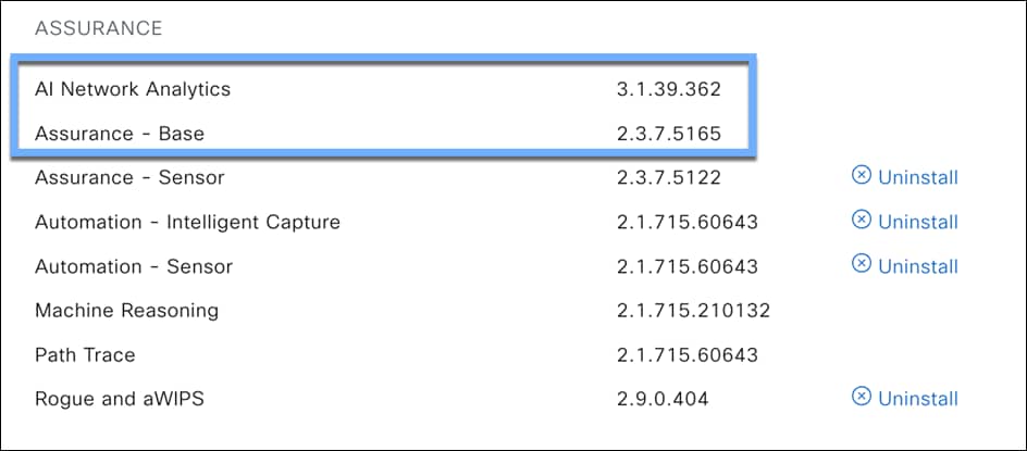
Install the AI Network Analytics package onto Cisco Catalyst Center
Cisco Catalyst Center provides the option to download a couple of packages called AI Network Analytics and Assurance – Base.
To download and install this package, follow the steps below:
● Click the hamburger menu top left corner of the screen. Click System, then Software Management.
● Click Currently Installed Applications on the top left side of the screen
● Scroll down to Assurance and you will find the AI Network Analytics and Assurance – Base packages ready for download and installation (Figure 2).
If you do not see the AI Network Analytics and Assurance – Base packages after performing the steps above, please contact a Cisco account sales representative or an account sales engineer for additional support.
Prepare 9800 Wireless controller
We recommend doing a DCA (Dynamic channel Assignment) for all bands while transitioning from Traditional RRM to AI-Enhanced RRM. This will help AI-Enhanced RRM recalculate the neighbors and efficiently assign channels.
Note: This is an optional but recommended step
Use this command in the 9800 Wireless Controller CLI:
To ensure the Wireless LAN Controller (WLC) you want to include can successfully connect as a member to the AI-Enhanced RRM RF Group Leader, it's essential that the RRM settings for all frequency bands on that WLC are configured with the Group Mode set to 'Automatic,' enabling automatic RF grouping.
If the controller is configured as a Static Leader and member controllers are assigned to it, ensure that the member controllers have the same RRM config and RF Profile settings before changing the leader configuration to Auto. Once set to auto, all the previously grouped controllers will automatically negotiate a new RF Group Leader, and the RF Group Leader will use the new RF Group Leader controllers RRM configs.
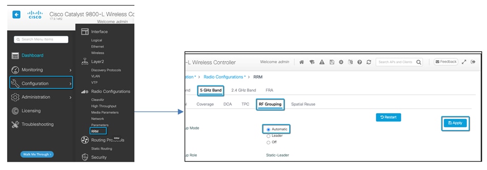
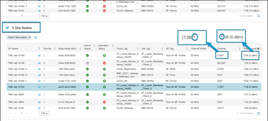
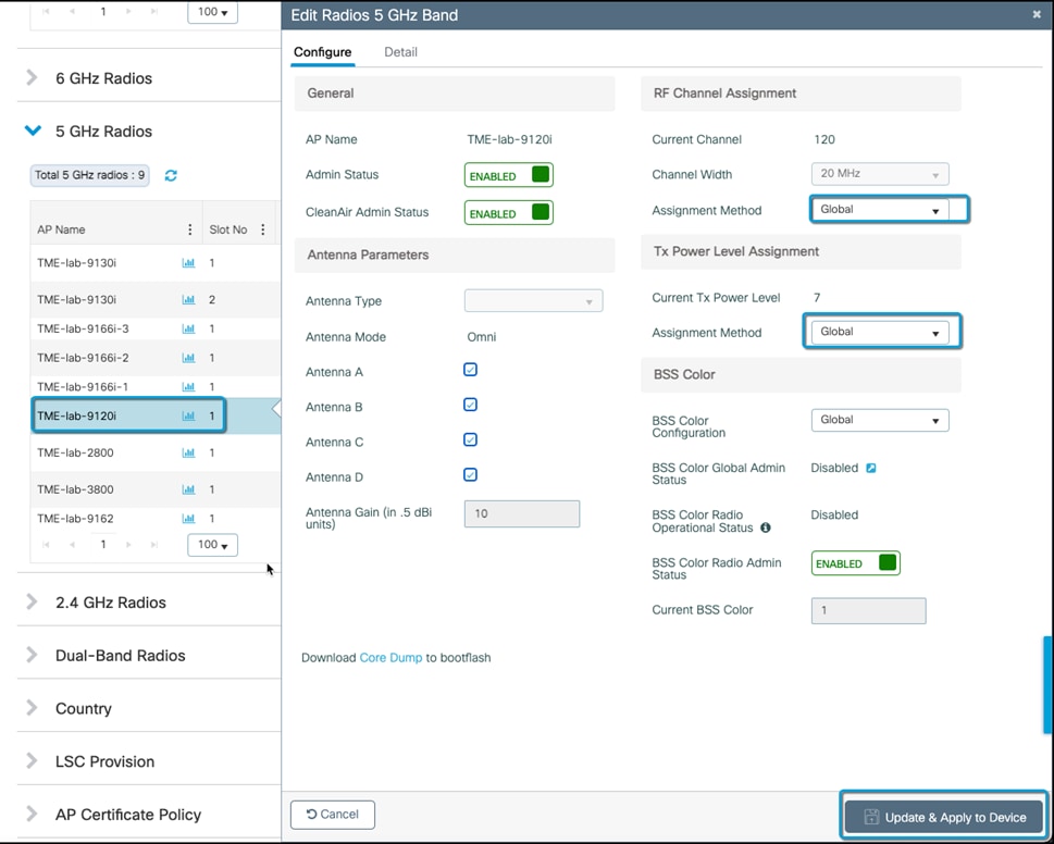
Note: In addition to setting RF Grouping to Automatic, ensure that RF channel Assignment and Tx Power Level Assignment for all radios operate Global mode (Automatic) and are not set to a static value on the AP Radio.
If you skip this step, the system may generate repeated false RRM change requests in the AI-Enhanced RRM Control Center. While this configuration is recommended, it is not mandatory. A subset of the radios can be on static channel and power settings, and AI-enhanced RRM will simply work on the other set of radios under automation mode.
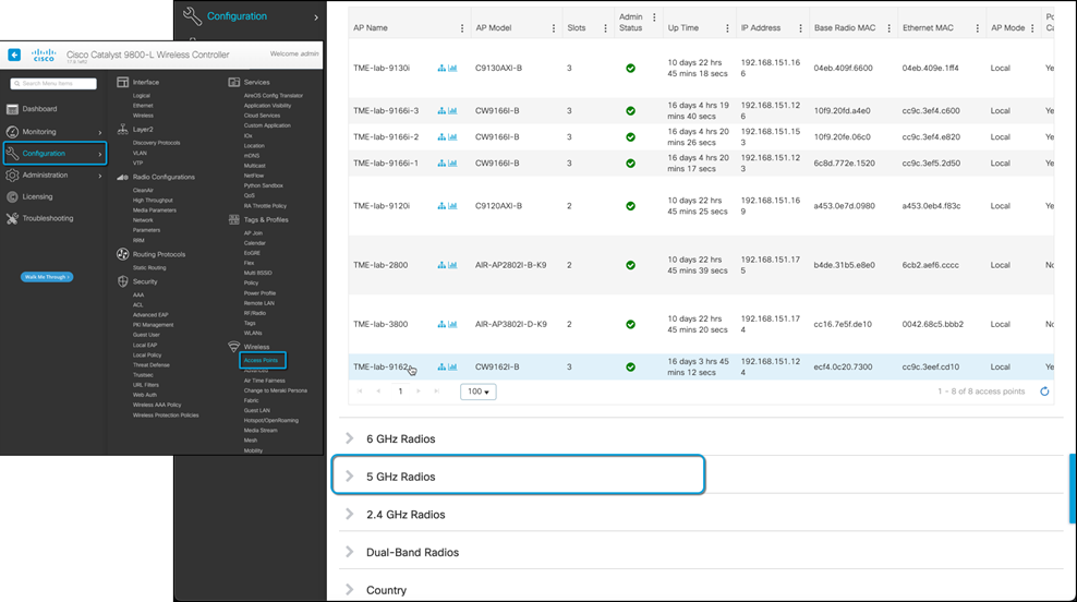
To do this, navigate on the sidebar Configuration > Access Points >Expand the 6 GHz /5 GHz /2.4 GHz Radios dropdown. If the Channel and Power Level values have Asterisk (*) in their values, they are operating in “Global assignment” mode and will be managed by AI-Enhanced RRM. Manage any radios not going through the radio configuration dialogue and set the channel and Power back to Global.
Part 1: Build a site hierarchy
You can create a network hierarchy that represents your network's geographical locations. The hierarchical organization enables you to easily apply design settings or configurations to a specific hierarchical element. For example, you can apply design settings to an entire area or to only a floor.
This step is important as AI-Enhanced RRM uses Building/Sites to group a Set of Access points to display the dashboard data and apply the AI-RF profile. After enabling the feature, you will click on the individual site to view the site-level view of the AI-Enhanced RRM control center.
Follow the below link to understand how to create Site Hierarchy:
https://www.cisco.com/c/en/us/td/docs/cloud-systems-management/network-automation-and-management/catalyst-center/2-3-7/user_guide/b_cisco_catalyst_center_user_guide_237/m_design-the-network-hierarchy.html
Part 2: Discovery and inventory
Description: Cisco Catalyst Center’s Discovery application allows a network administrator to add their network device to the platform.
Section goals: Discover WLC and APs and assign them to the site created in the previous section.
Make sure to assign location to WLCs and Access points. This is a pre-requisite for AI-Enhanced RRM.
Follow the below link to get more information on how to discover your devices and add them to inventory:
https://www.cisco.com/c/en/us/td/docs/cloud-systems-management/network-automation-and-management/catalyst-center/2-3-7/user_guide/b_cisco_catalyst_center_user_guide_237/b_cisco_dna_center_ug_2_3_7_chapter_010.html
Part 3: Enable Cisco AI-Enhanced RRM
Description: Cisco Catalyst Center’s Cisco AI Analytics page provides an option to enable all AI Analytics features and allows you to select a cloud cluster where the data will be store for AI Algorithms to process.
Section goals: Enable AI-Enhanced RRM and choose a cloud cluster where your data will be stored.
Prerequisite: To enable AI Network Analytics, Access Points and 9800 Wireless Controller need to be a part the inventory.
Step 1: Navigate to the Cisco AI Analytics page.
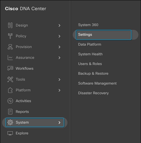
1. Click the hamburger menu in the top left corner of the screen. Click System, then Settings
2. Navigate to Cisco AI Analytics on the sidebar as shown.
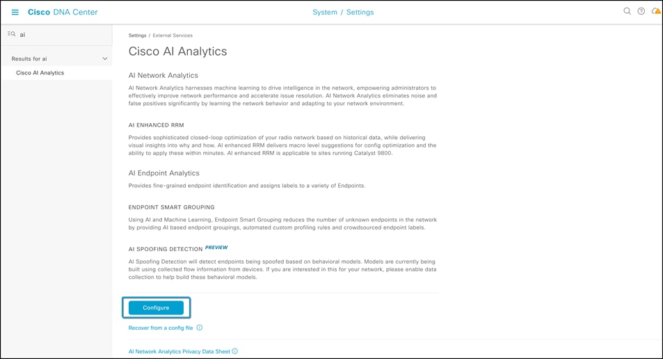
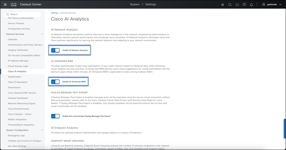
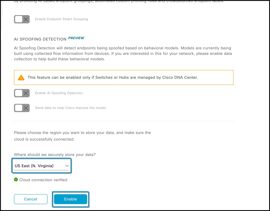
Step 2: Enable AI-Enhanced RRM
To allow Cisco Catalyst Center turn on AI-Enhanced RRM, you need to
1. Enable AI Network Analytics and AI-Enhanced RRM
2. Select the closest or preferred cloud cluster you would want to store your cloud data.
3. Make sure the cloud connection status is green and click enable.
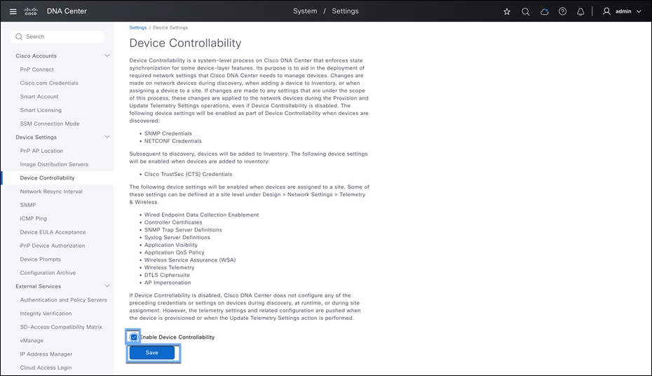
Step 3: Enable Device Controllability
This Feature requires customers to enable Device controllability as Catalyst Center will be managing the RF profiles and RF Tags on the 9800 Wireless controller. To enable this, click hamburger menu > System > Settings > Device Controllability.
Click on the Enable Device Controllability check box and hit SAVE.

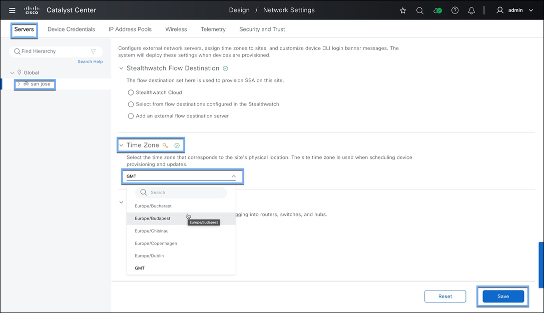
Step 4: Sitewise Timezone
The time zone needs to be set for every area to make sure this feature works efficiently. By default, UTC time zone is set to all locations if not set otherwise.
To do this
1. Click the hamburger menu icon and choose Design a Network Settings a Servers tab.
2. If all your sites are in the same time zone, select global in the Hierarchy selection.
3. Select the 1st site in the Hierarchy selection if you have different time zones.
4. Scroll down to the Time Zone section and select the correct time zone of the site, depending on the exact physical location.
5. Repeat the same for all different locations.
Part 4a: AI-Enhanced RRM Workflow for v2.3.7.4 and above
Description: This new workflow will help users to enable AI-Enhanced RRM in a simpler way with and without device provisioning.
If using Device provisioning workflow, make sure to have a pre-deployed network profile and have the devices assigned to respective sites.
Different ways of launching this workflow:
● Hamburger menu > Assurance > AI-Enhanced RRM
● Hamburger menu > Workflow > AI-Enhanced RRM
● Hamburger menu > Design > Network Settings > Wireless > RF Profile > AI RF Profile > Action button
Let us talk about 1st way of launching the workflow.
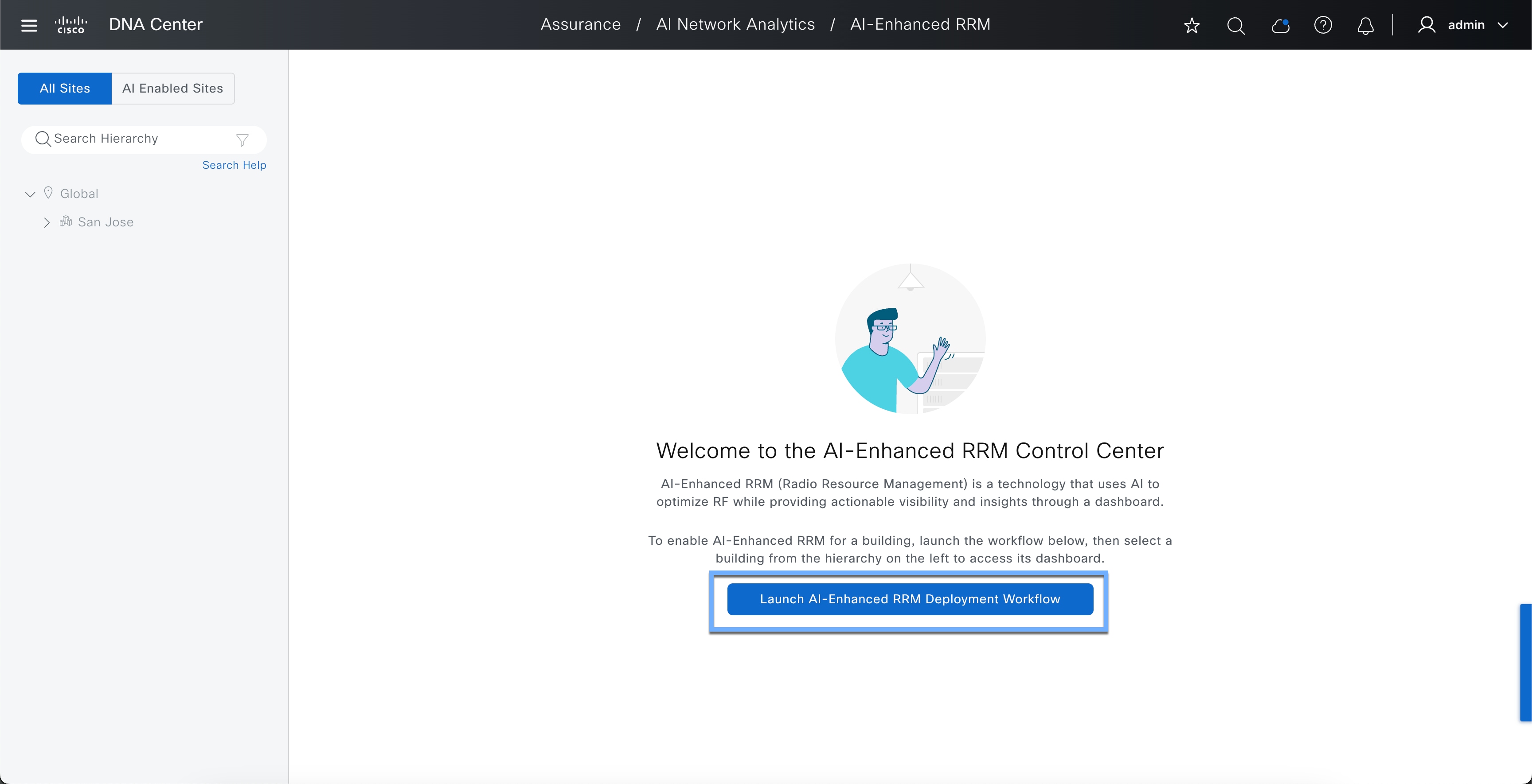
Step 1: Launch AI-Enhanced RRM Deployment Workflow
Click the Hamburger menu icon > Assurance > AI-Enhanced RRM
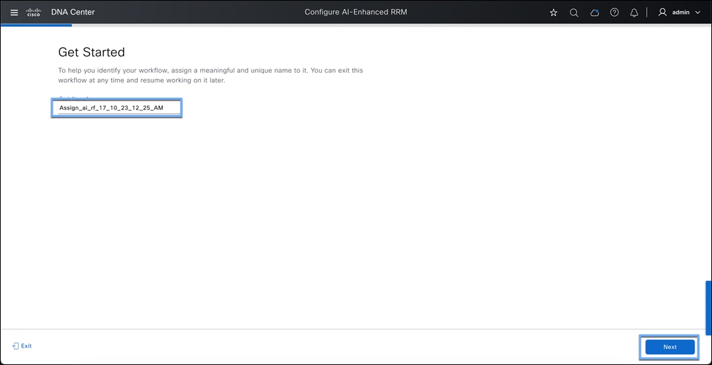
Step 2: Assign a name to the task and click Next.
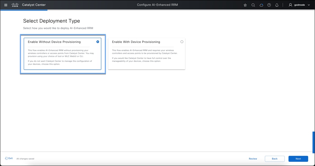
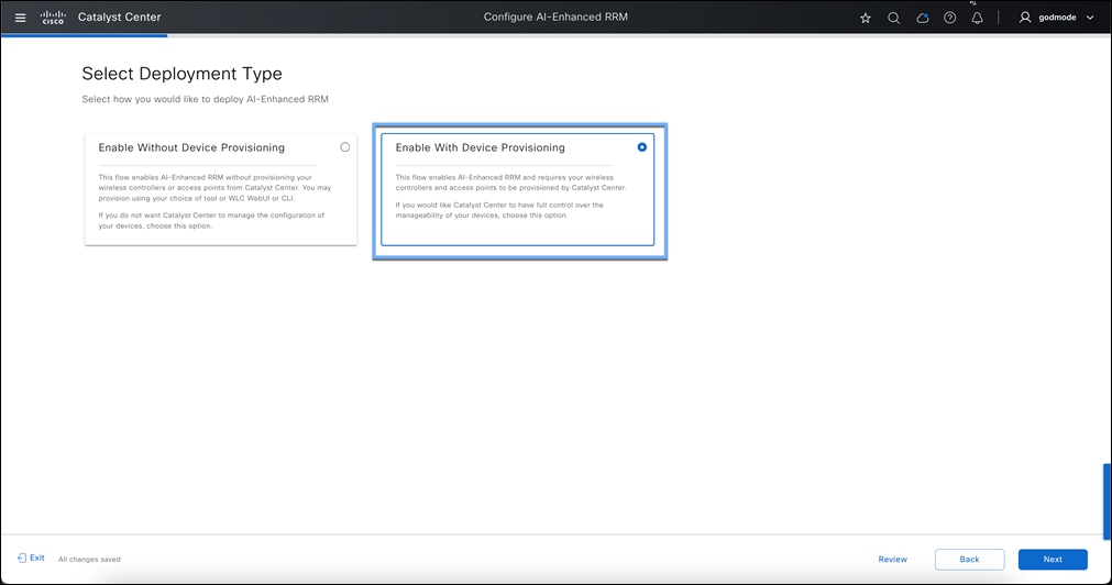
Step 3: Select Deployment type.
This page allows customers to choose between Device Provisioning and non-Device provisioning workflow.
● With Device Provisioning: When employing device provisioning, network profiles within Cisco Catalyst Center are utilized to administer the entire 9800 Wireless Controller. This approach necessitates that users provision both their Cisco Catalyst 9800 Wireless Controller and Access Points using the designated network profile. All configurations are done through Profiles that are maintained on Catalyst Center.
● Without Device Provisioning: For users who choose not to provision their 9800 Wireless Controller through Cisco Catalyst Center, there is an alternative method that enables the management of RF configurations directly via the Catalyst Center, while all other settings are managed locally on the Catalyst 9800 Wireless Controller itself. In this scenario, the user employs the local GUI or CLI to configure the WLC, and the Catalyst Center is utilized solely for monitoring purposes, providing assurance and AI-Enhanced RRM services.
3A: Without Device Provisioning workflow:
This process allows for AI-Enhanced Radio Resource Management (RRM) without needing to configure your wireless controllers or access points through Catalyst Center. You have the flexibility to provision using your preferred tool, the WLC WebUI, or CLI. If you prefer not to have Catalyst Center handle your device configurations, select this option.
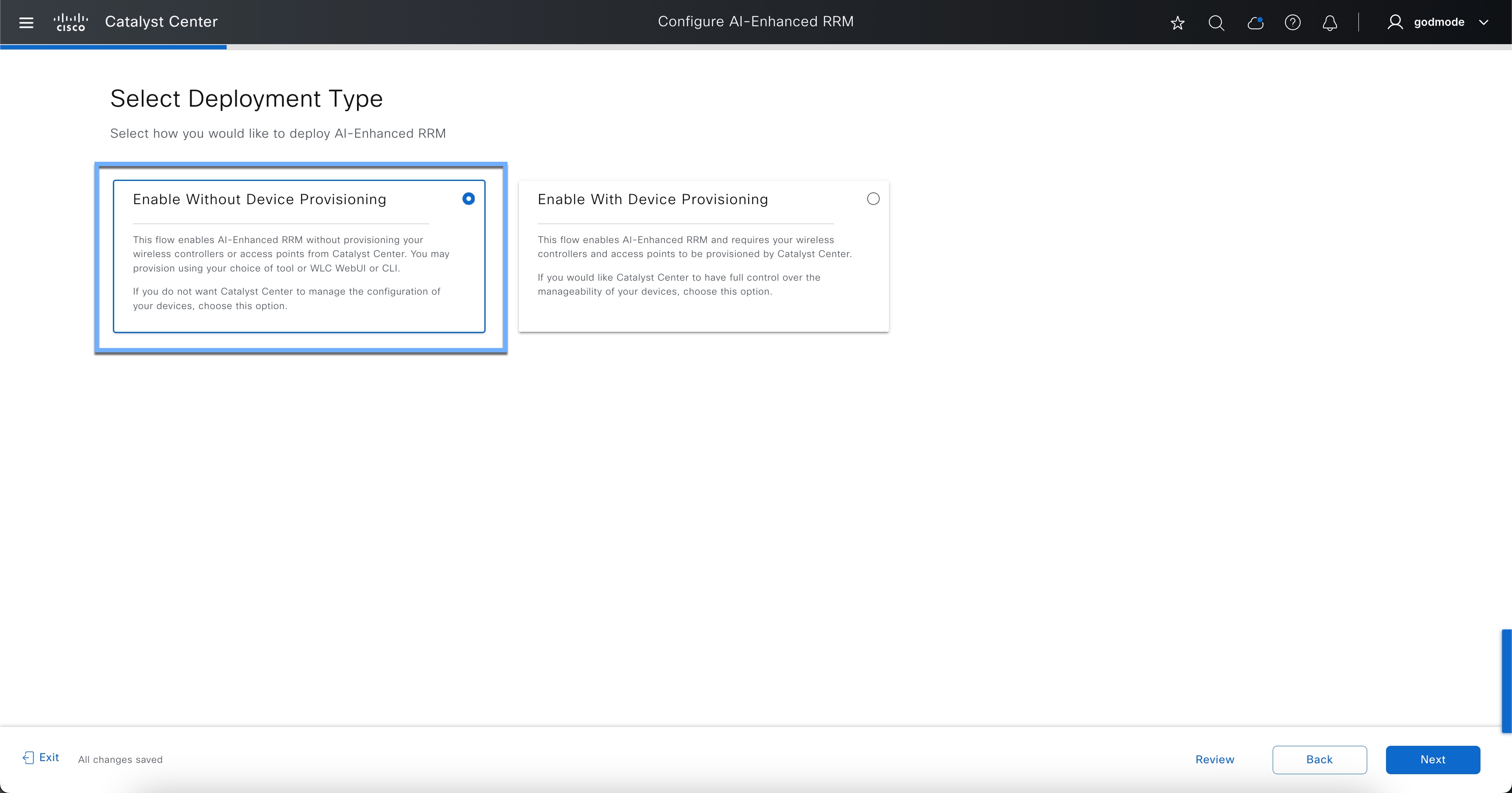
3B: With Device Provisioning workflow:
If a user has provisioned their 9800 Wireless controller with a Network profile before this setup (Using Catalyst Center Network profile-based Automation), they will select Enable with Device Provisioning.

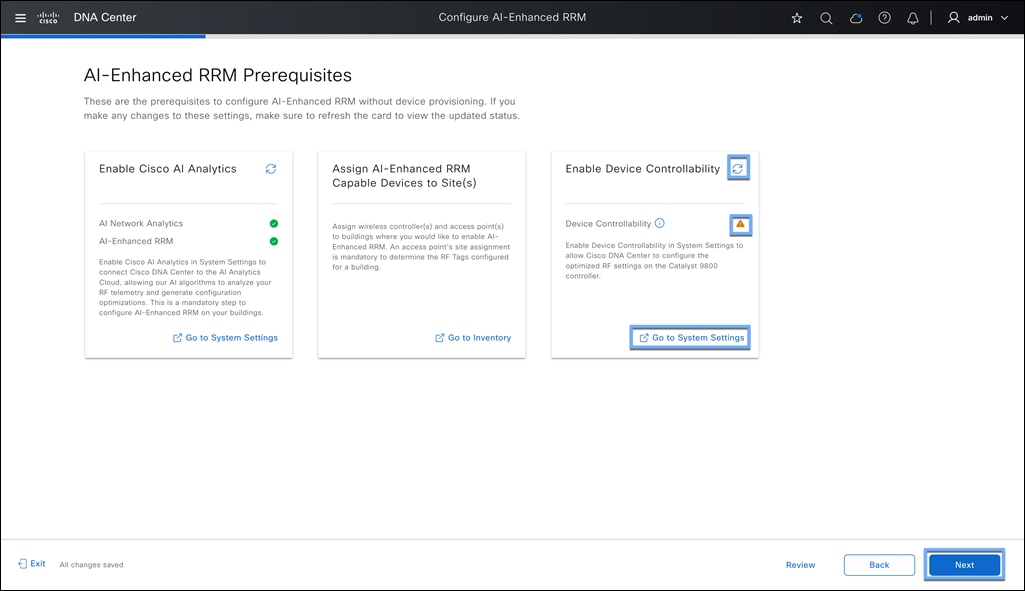
Step 4: Prerequisites check
At this stage, if you have not met with any prerequisites, this page will call it out and have a red cross or error sign like shown below. You can select the redirect allow icon which will take you to the settings page to enable the needful. Once enabled, you can hit the individual refresh button in the tile and then hit next.
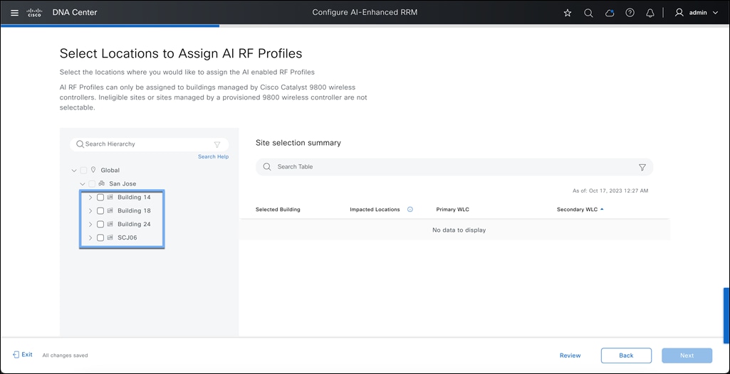
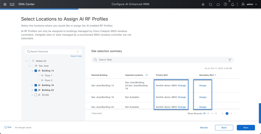
Step 5: Select the location to assign the AI RF Profile
AI-Enhanced RRM is enabled at the WLC level globally, just like RRM. All sites having APs associated with the controller assigned to other buildings will also be managed by AI-Enhanced RRM; the workflow supports this, and all impacted sites will be listed as Impacted and assigned as well. Make sure to add all the sites associated with 1 controller.
Note: v2.3.7.4/5 supports 20 building selections at a time. If you have more than 20 buildings in a WLC, split out the building selections.
Select the buildings in the same 9800 controller at this step.
5A: Without Device Provisioning workflow:
If you have some sites not selected from the same controller, the system will alert you via a pop-up warning saying more locations in this WLC have not been selected. All sites on a given controller must run the same RRM algorithm. If there are sites associated with the controller that have not been selected
To mitigate this, choose “Select more Locations” and go back to site selection, adding the remaining buildings.
Note: Catalyst Center does channel validation and enforcement based on the location (address mapped to the buildings) where the APs are assigned even when using "Enable Without Device Provisioning” Example - If a building is mapped to Spain, and the user has added a list of 5ghz channels including channel 157,161, Catalyst Center would not push 157 and 161 since Spain does not support these channels
WARNING: In this step, it's crucial to select all the buildings that are associated with the same 9800 WLC. If you proceed with "Continue with Current Selection" without including all the relevant buildings and their access points, the unselected sites and APs will be excluded from receiving RRM services. This will result in APs staying in their default values and not participating in any RRM calculations.
The reason for this recommendation is that only one RRM algorithm can operate per controller. All access points managed by a given controller share the same RRM process—whether traditional RRM or AI-Enhanced RRM. Once AI-Enhanced RRM is enabled, it governs the entire controller.
5B: With Device Provisioning workflow
After building selection, a consent window pops up to make sure you have a network profile assigned to the WLC.
For onboarding Without Device Provisioning see Step 6. With Device Provisioning proceeded to Step 7.
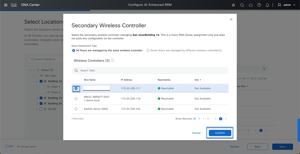
Step 6: Select with Primary and Secondary WLC
At this step, please select the Primary WLC for each site.
In case of having multiple controllers in the same building, you can select individual wireless controllers for each floor in this page.
Hit confirm once done.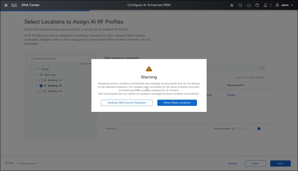
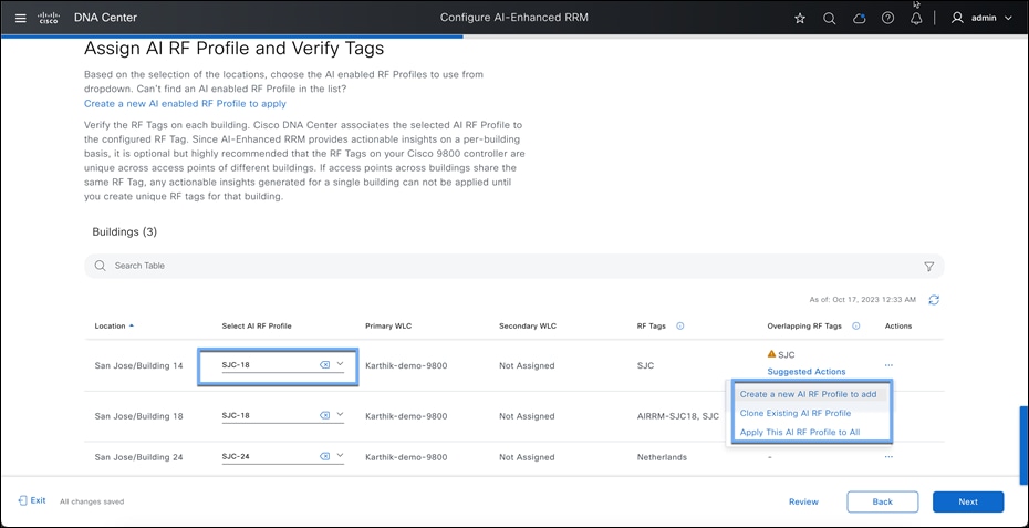
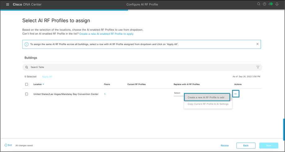
Step 7: Select the AI RF Profile to assign.
You can select from a previously configured AI RF Profile, or by selecting the actions menu “Create a new AI RF Profile to add” or “Clone Existing AI RF Profile”. Let us create an AI-RF profile using this workflow.
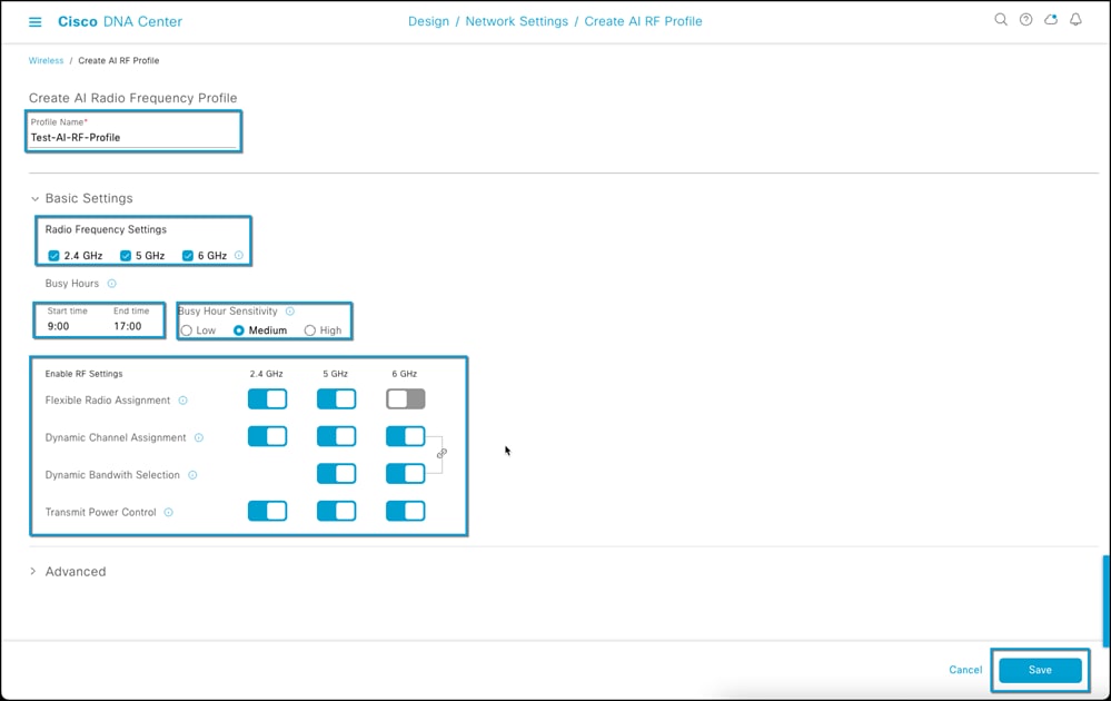
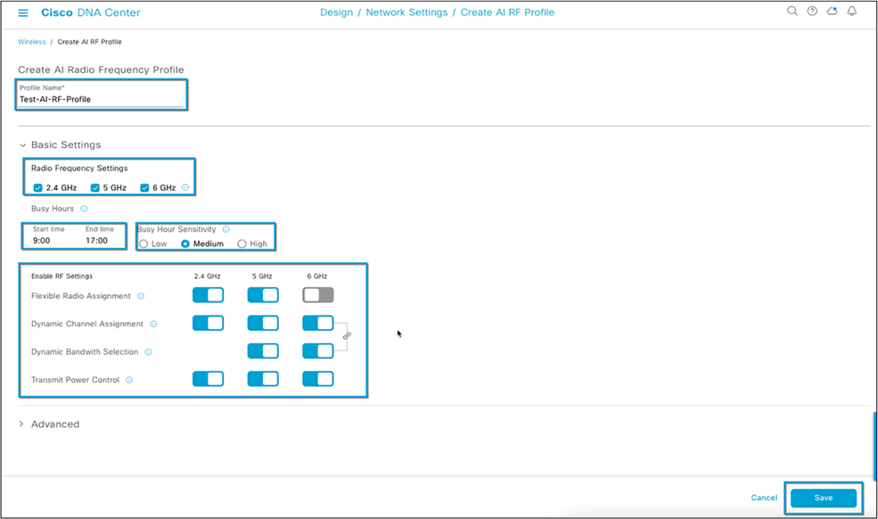
Step 8: Creating a new AI RF Profile
● Enter a Name to the AI RF Profile
● Select the Bands you want AI-Enhanced RRM to manage.
● Enter the Busy Hour of your network and how sensitive your network is to RRM Changes
● Enable all the Algorithms you want to use in this AI RF profile.
What is Busy Hour? The concept of 'Busy Hour' refers to the time period during which your network experiences the highest levels of activity and to make optimizations tailored for that period. This optimization is usually applied after busy hour unless necessary. 'Busy Hour Sensitivity' is a specific setting that adjusts how responsive the AI-Enhanced RRM is in optimizing radio frequency during these identified busy periods.
● High Sensitivity - RRM optimizations will occur whenever RF improvements are possible.
● Medium Sensitivity (Default mode) - RRM optimizations will occur less frequently than high sensitivity.
● Low Sensitivity - RRM optimizations will only be crucial changes affecting operations, and the rest of the changes will be deferred until after the configured busy hour.
Crucial changes include:
◦ DFS hits
◦ ED-RRM
◦ RF Jammer
◦ Persistent, excessive co-channel interferences from nearby rogues
Note: Sensitivity outside the configured busy hour is equivalent to high sensitivity
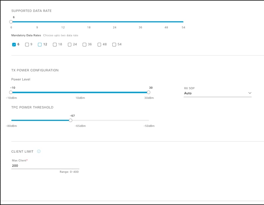
An AI RF Profile contains the same elements as a legacy controller-based RF Profile but adds the service configurations and other element configurations to which it will be subscribed.
The Services include:
● FRA – Flexible Radio Assignment
● DCA – Dynamic Chanel Assignment
● TPC – Transmit Power Control
● DBS – Dynamic Bandwidth Selection
Note: At least 1 of the 4 (FRA, DCA, TPC and DBS) AI-Enhanced RRM services must be enabled to onboard a site in AI-Enhanced RRM Service.
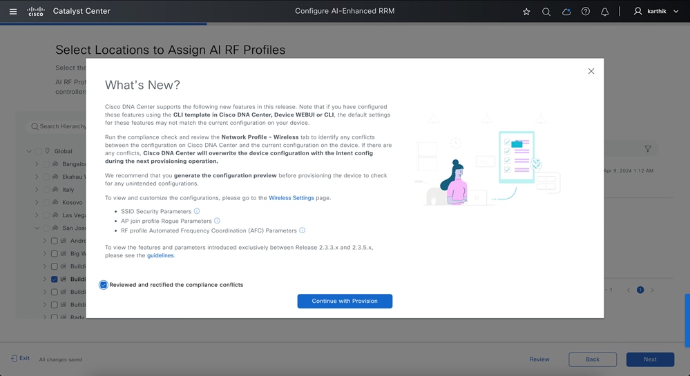
Any changes or corrections can be made at this time and saved. The profile only exists on the Cisco Catalyst Center at this point. Until the devices are provisioned and have profiles (either classic or AI) selected and pushed, no changes are made to the controllers or the associated APs operational configurations.
When satisfied select “Save” to complete the action. Upon saving you will be returned to the AI RF-Profiles main screen showing the results of the actions.
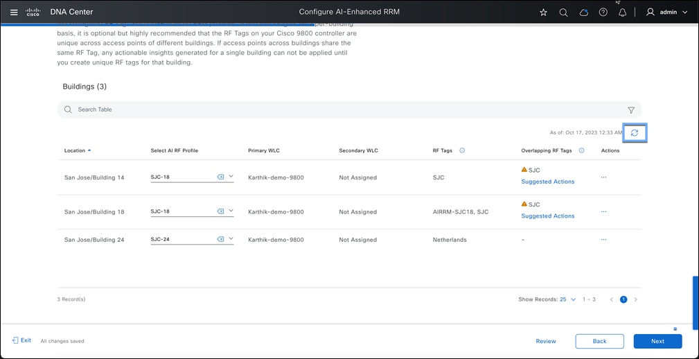
You can apply the same AI RF profile to all the selected buildings.
Note: We recommend using individual RF profiles per Building
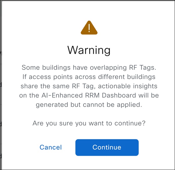
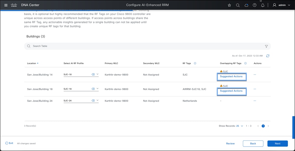
Should you encounter a scenario where RF tags are duplicated across multiple buildings, the workflow will alert you to the potential issue of applying identical AI-RF profiles to these buildings. To resolve this, you can follow the outlined steps to alter the RF tags within your 9800 controller. Not a mandatory step, just a recommendation.
The caveats of overlapping tags are that getting an insight on a particular site with overlapping RF Tags will restrict you from applying the insights directly. As a workaround, you can use the suggested action to create new RF Tags and then apply Insights.
This warning will inform you that you have overlapping RF tags and ask if you still want to proceed.
Step 9: Resolving Overlapping RF Tags (Optional Step)
Note: This step is only applicable for Without Device provisioning workflow.
Overlapping RF Tags means you have access points across multiple buildings sharing the same RF-Tag on 9800.
When you share overlapping RF Tags across different sites on the 9800, we will be restricted to using the same AI-RF profiles for those shared RF tag buildings. The reason for that is that this workflow can only modify the RF tag settings with 1 per band RF profile on 9800.
This is not a blocker but will lead to sharing AI-RF profile settings across buildings, including busy hours. In such situations, we will block applying Insights on a per-site basis as it will make an overall AI-RF profile change, which could impact multiple locations.
If you want to eliminate this warning and create individual Rf tags per site, we suggest some actions. You can click on Suggested Actions on individual sites:
We have 3 options for you here:
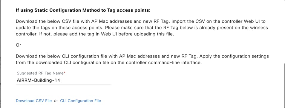
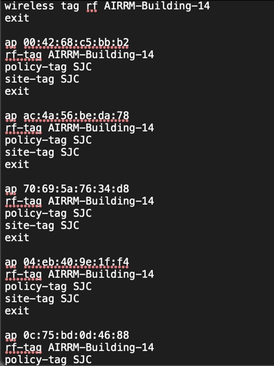
1. Create a new RF-Tag and take a CLI dump to paste it to the 9800.
This CLI template can be directly copied to the 9800 CLI in the Config Terminal.
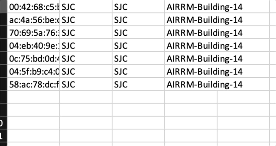
2. CSV with all the AP mac on this site.
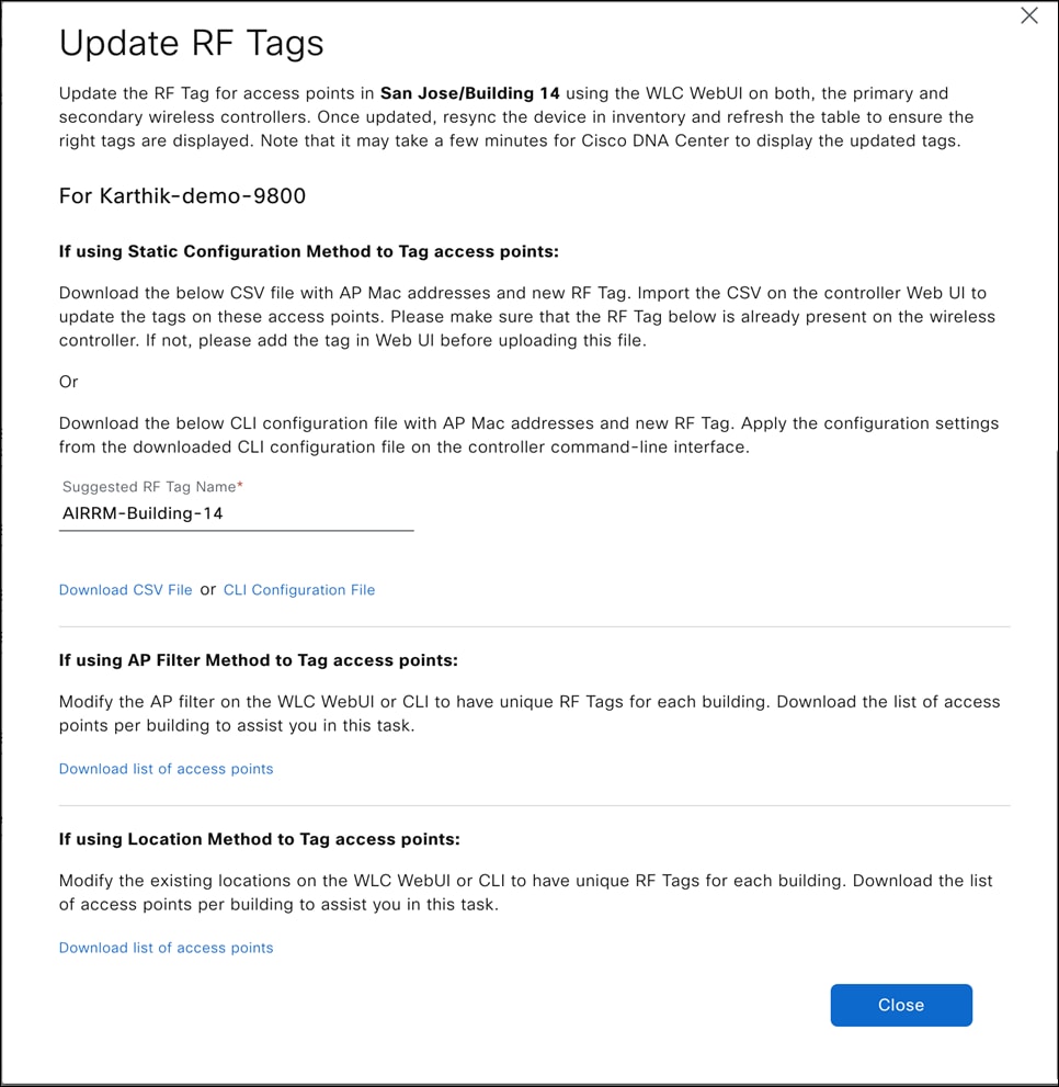
The CSV file provided can be used for Static Tagging, which will give a list of APs with the respective Policy Tag, Site Tag, and the new RF Tag mentioned in the Suggestive Action page.
1. RF Tag name "AIRRM-Building-14" from the suggested RF Tag name should be manually added on 9800.
2. Then use the downloaded .csv to upload through 9800.
Note: 9800 only supports an upload limit of 20Kb. The CSV file download will be limited to 20Kb and bundled into multiple CSV files in a zip format.
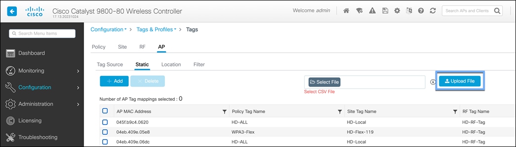
To import the CSV on 9800, you go to Configuration > Tags > AP > Static.
To import the CSV on 9800, you go to Configuration > Tags > AP > Static.
Note: If you have a zip file downloaded from the workflow, make sure to unzip the file and upload 1 CSV file at a time.
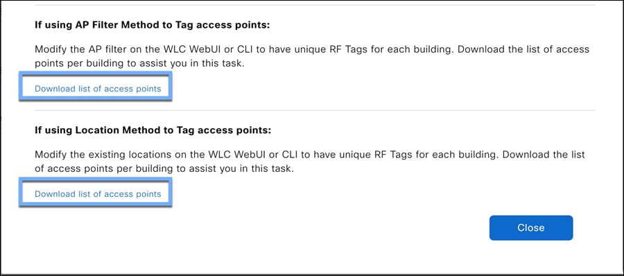
3. CSV to import into rule-based tagging.
You can download the AP MAC address list in CSV format for this site and import it to the location/Filter based tagging.

Note: This list only has APs for 1 selected site. Make sure to do this for all the sites with suggested actions.
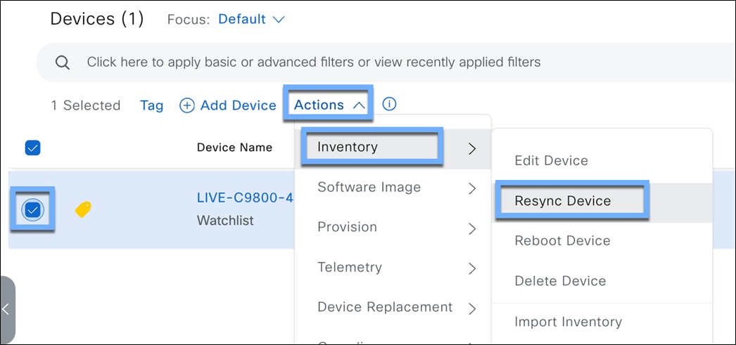
Once you have modified the 9800 with new RF tags, you will have to resync the 9800.
To do that, Open a new tab for the Catalyst Center.
● Hamburger menu > Provision > Inventory
● Select the 9800 where these changes have been made > Click Action > Inventory > Resync Device
Once the device has been successfully resynced, go back to the workflow, and hit the refresh button on the page. This should detect your new RF Tags and remove the warning for the respective sites.
Note: Refreshing will take time in a high AP scale environment. You can resume the workflow in 15 mins.
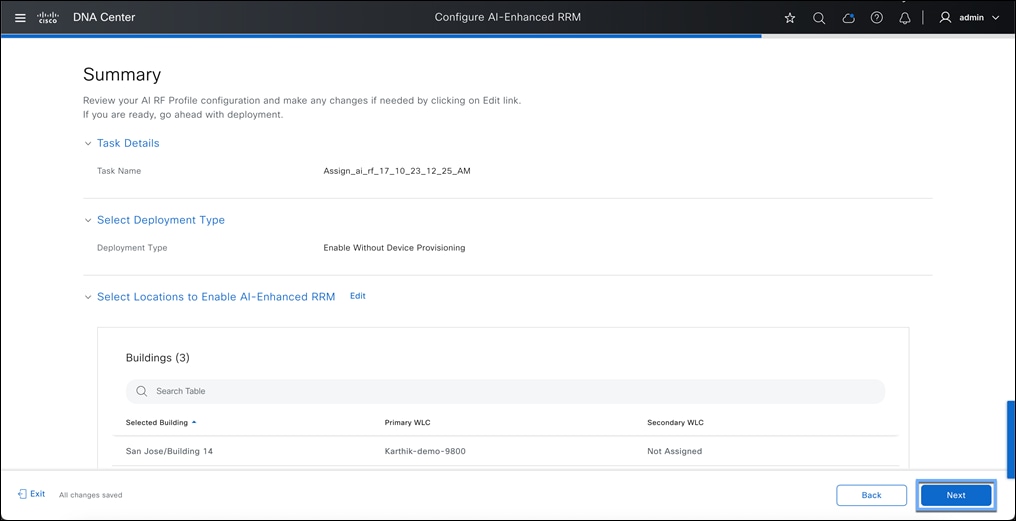
Step 10: Review and verify the Summary.
On the summary page, all the configurations from the AI RF Profile will be listed out along with the site assignments. Click next once verified.
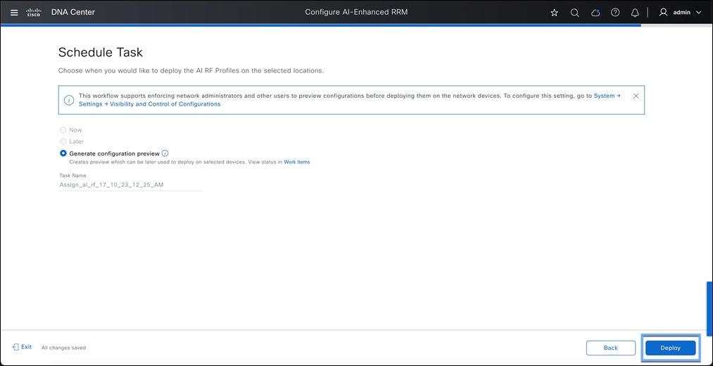
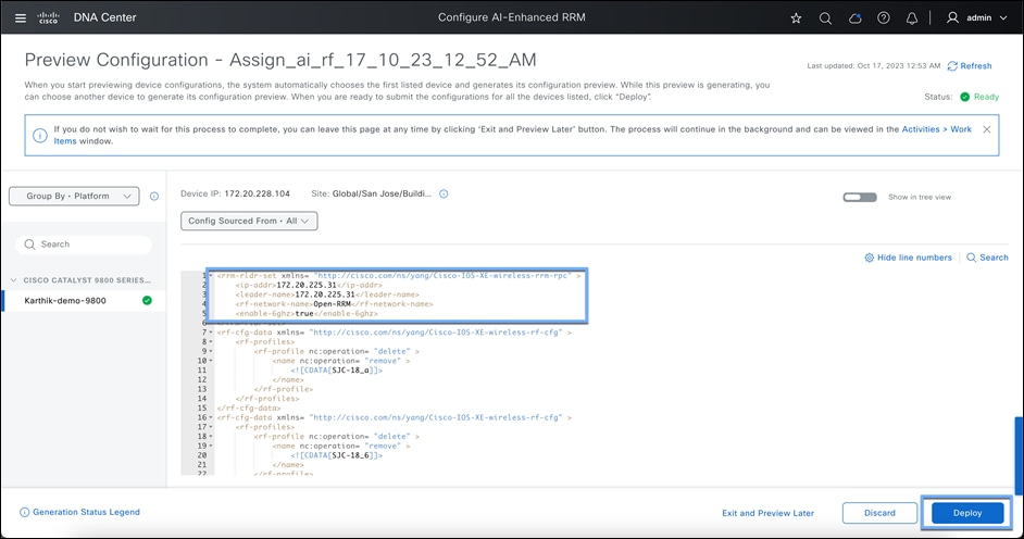
Step 11: Configuration Generator
Selecting next will push the AI RF Profile to the selected WLC and APs once provisioned. As with legacy RF Profiles, changing or applying an RF Profile causes a CAPWAP reset and momentarily disrupts AP connectivity.
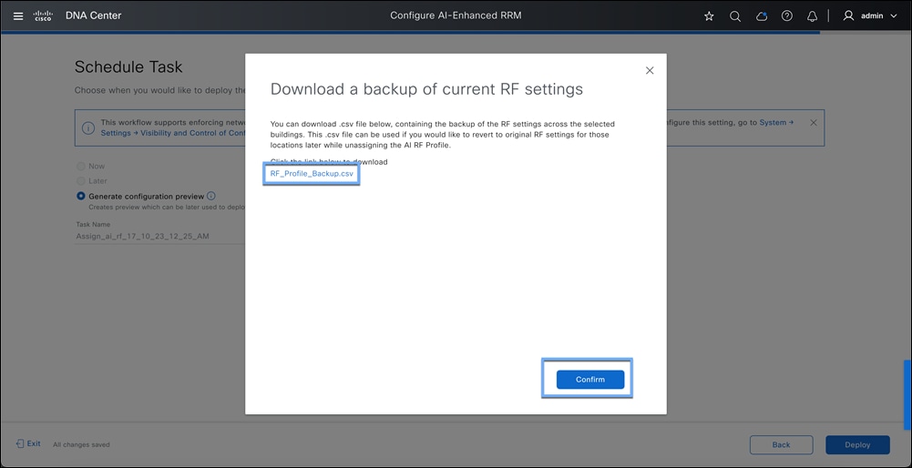
Download backup profile consist of you the AP to RF profile mapping. This CSV can be used to import while unassigning AI-Rf profile from a WLC. This will roll back to original customer configuration.
The generate config preview page will show all the configs being pushed from Catalyst Center to 9800. This workflow will involve:
● Changing the RF group leader for each band
● Adding RF profiles for 2.4,5 and 6Ghz
● Modifying RF profiles on the respective RF Tags.
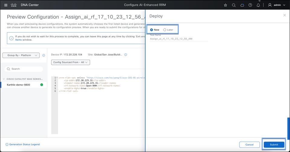
AI RF Profile deployment can be done now or can be scheduled for a non-operational hour.
Once you hit submit, AI-RF profile is pushed to the 9800 in for of 3 RF profiles for each band.
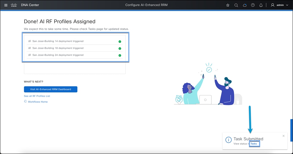
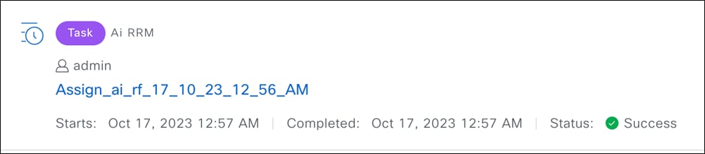
When you click on Tasks, you will see the task progress. Once the task has successfully completed, you can go back to AI-Enhanced RRM Page and look at the AI enabled sites.
Step 12: Verify the Assignment
Verify AI RF Profile is successfully assigned to the Site.
● Go to the Hamburger Menu > Assurance > AI-Enhanced RRM
● Use the Site Hierarchy sidebar and navigate to the site where AI RF Profile is deployed.
● An AI logo will be shown along with highlighting the site name, which confirms AI RF Profile is successfully assigned to the site.
Note: It takes about 30 mins to get data populated on the AI-Enhanced RRM Control center after enabling the solution.
Part 4b: AI-Enhanced RRM Workflow for v2.3.7.3 and below (Older versions)
Create an AI RF profile
To add a site to the AI-Enhanced RRM service to manage the sites and APs’ RRM, you must create an AI RF profile. If you have learned the profiles and configurations from the controller already (via the Learn Device Configuration workflow), you can convert an existing RF profile to an AI RF profile. There is also a workflow for creating and assigning an AI RF profile to a site.
Option 1: Creating AI RF Profile from Network Settings
● Click the hamburger menu icon and choose Design > Network Settings > Wireless Tab > Global.
● On Sidebar > Scroll down to Wireless Radio Frequency Profile.
● You can check the box for an existing RF profile > go to Actions and select Upgrade to AI.
● To create a brand-new AI RF Profile, select +Add > AI RF Profile and customize the AI RF profile according to your wireless network requirements.
● Go to the AI RF Profile tab to find your newly created AI RF Profile.
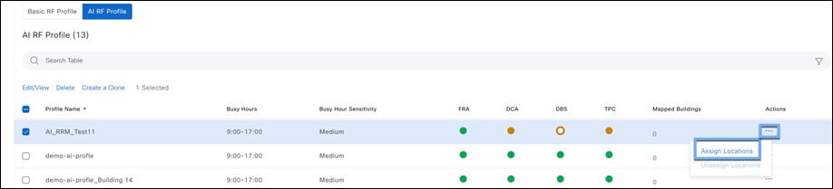
● To assign this AI RF Profile to a site, on your AI RF Profile column click on … then go to Assign Locations
● Select all the buildings you want to assign this AI RF Profile to and want to use AI-Enhanced RRM, then select Assign.
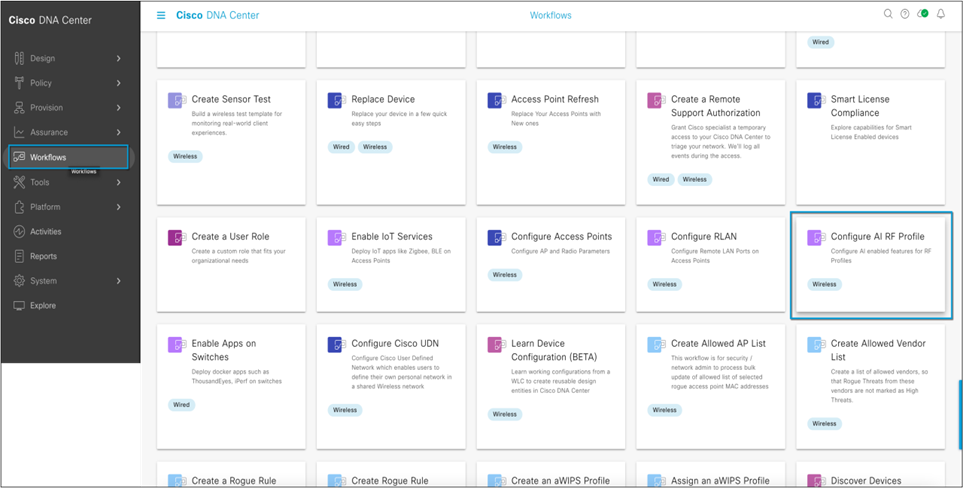
Option 2: Creating AI RF Profile using a Workflow.
Step 1: Create an AI RF profile.
Click the hamburger menu and choose Workflows > Configure AI RF Profile.
 |
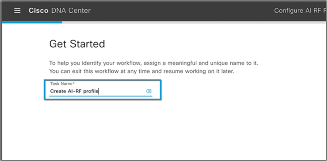
Step 2: Assign a name to the task and click Next.
 |
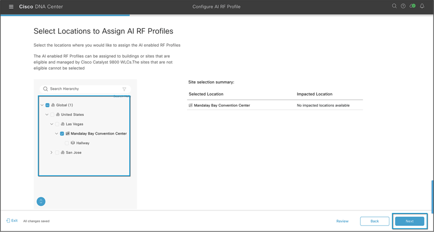
Step 3: Select the location to assign the AI RF profile.
AI-Enhanced RRM is enabled at the WLC level globally, just as RRM is. All sites having APs associated with the controller but assigned to other buildings will also be managed by AI-Enhanced RRM; the workflow supports this. All impacted sites will be listed as Impacted and assigned as well.
Select the site(s) to assign and click Next.
 |
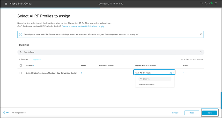
Step 4: Select the AI RF profile to assign.
You can select from a previously configured AI RF profile or select the Actions menu and choose “Create a new AI RF Profile to add” or “Copy the currently assigned RF Profile and AI Settings.”
 |
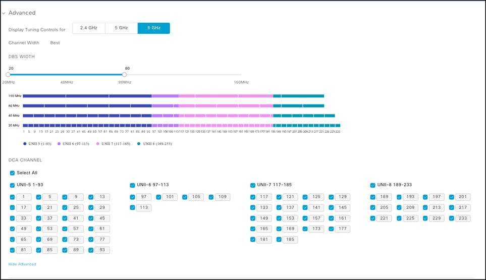
Step 5: Create a new AI RF profile (6-GHz support starts with Cisco Catalyst Center Release 2.3.4)
● Enter a name for the AI RF profile.
● Select the bands you want your network to operate on.
● Enter the busy hour of your network and how sensitive your network is to RRM changes.
● Enable all the algorithms you want to use in this AI RF profile.
What is the busy hour? It determines when RRM optimizations will occur based on how sensitive your network is to changes:
● High Sensitivity - RRM optimizations will occur whenever RF improvements are possible.
● Medium Sensitivity (Default mode) - RRM optimizations will occur less frequently than high sensitivity.
● Low Sensitivity - RRM optimizations will only be crucial changes affecting operations, and the rest of the changes will be deferred until after the configured busy hour.
Crucial changes include:
◦ DFS hits
◦ ED-RRM
◦ RF Jammer
◦ Persistent, excessive co-channel interferences from nearby rogues
Note: Sensitivity outside the configured busy hour is equivalent to high sensitivity
An AI RF profile contains the same elements as a legacy controller-based RF profile but adds configurations for services and other elements that will be subscribed to.
The services include:
● FRA: Flexible Radio Assignment
● DCA: Dynamic Chanel Assignment
● TPC: Transmit Power Control
● DBS: Dynamic Bandwidth Selection
Note: At least one of the four AI-Enhanced RRM services (FRA, DCA, TPC, and DBS) must be enabled to onboard a site in the AI-Enhanced RRM service.
Any changes or corrections can be made at this time and saved. The profile exists only on Cisco Catalyst Center at this point. Until the devices are provisioned and have profiles (either classic or AI) selected and pushed, no changes are made to the controllers or the associated APs’ operational configurations.
When satisfied, select Save to complete the action. Upon saving you will be returned to the AI RF profiles main screen showing the results of the actions.
 |
 |
Step 6: Assign an AI RF profile to a site.
Select an AI RF profile to assign to the site, as shown in Figure 53.
 |
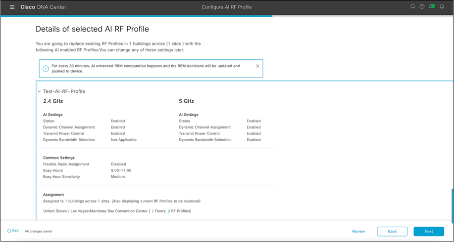
Step 7: Review and verify the summary.
All the configurations from the AI RF profile will be listed on the summary page, along with the site assignments. Click Next once you have verified the information.
 |
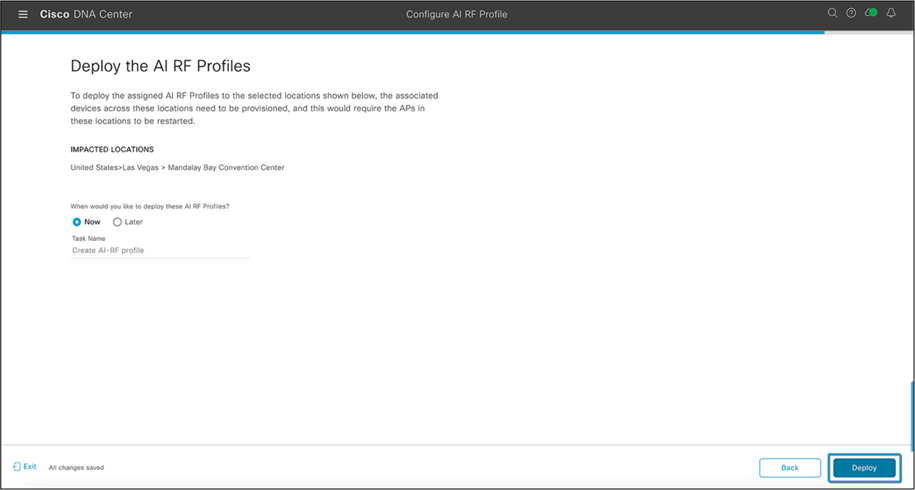
Step 8: Choose when to deploy the AI RF profile.
AI RF profile deployment can be done now or can be scheduled for a nonoperational hour.
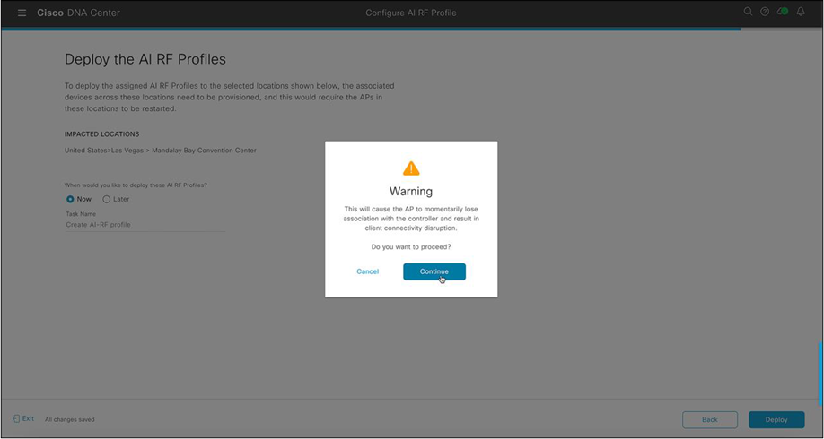
Selecting Next will push the AI RF profile to the selected WLC and APs once provisioned. As with legacy RF profiles, changing or applying an RF profile causes a Control and Provisioning of Wireless Access Points (CAPWAP) reset and momentarily disrupts AP connectivity. A warning is displayed, as shown in Figure 71.
 |
 |
Part 5: Verifying AI-Enhanced RRM deployment
Cisco Catalyst Center Verification
Go to Enhanced RRM page and select the site with AI RF Profile. The AI-Enhanced RRM controller should be up and should be collecting data from the controller and access points.
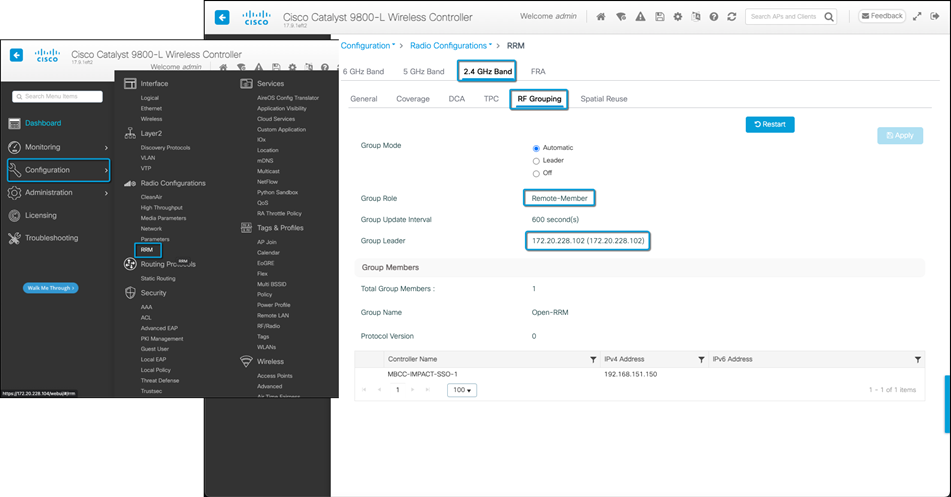
Catalyst 9800 Wireless Controller Verification
Step 1: Verifying RRM group leader.
On the Wireless 9800 controller, go to Configuration > RRM > 6/5/2.4Ghz Band > RF Grouping.
● The Group Role should be Remote-Member.
● The Group Leader should be the Cisco Catalyst Center’s IP address.
Day-1 AI-Enhanced RRM features and use cases
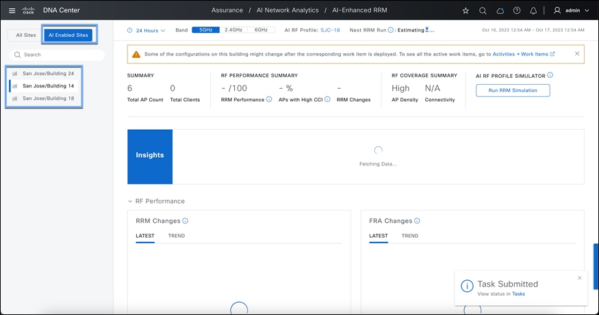
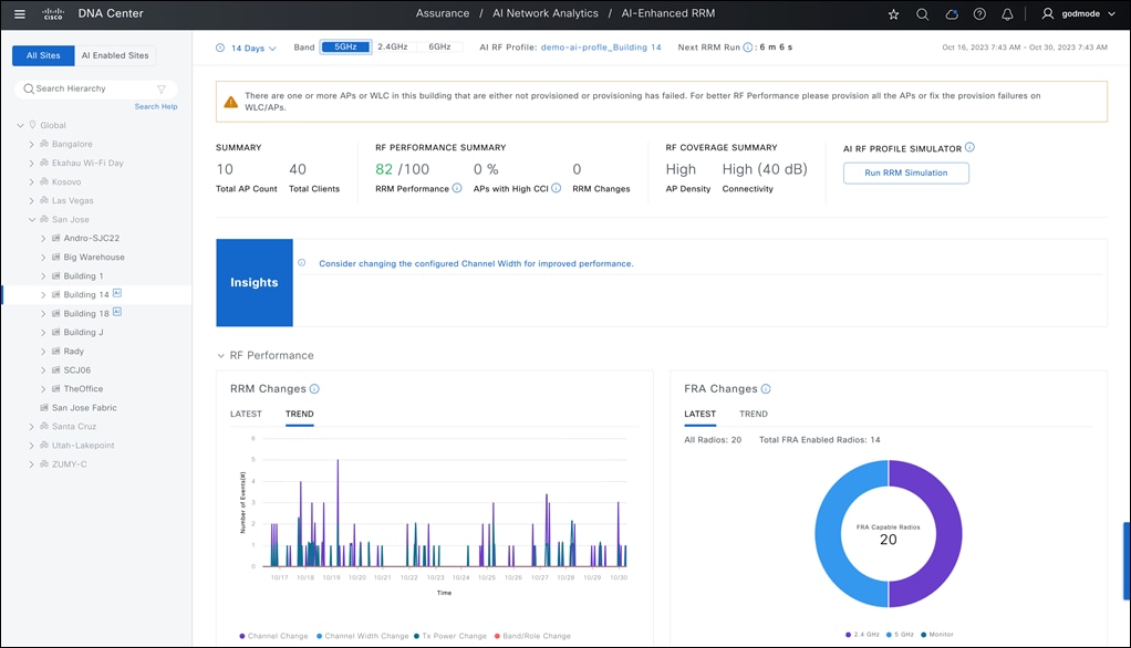
The heart of AI-enhanced RRM Management is in the RRM Control Center, where information regarding the current (Latest) and Trend information regarding current actions and overall performance can be visualized.
Each element on the dashboard has tool tips that explain what it means or how it's measured.
At the top of the page is the focus selections. This sets the context for the information being displayed on the page. Selections for timespan are 24 hours, 7 days, or 14 days (the current maximum data period). Band Selection of 2.4 or 5 GHz, and the AI RF Profile in use.
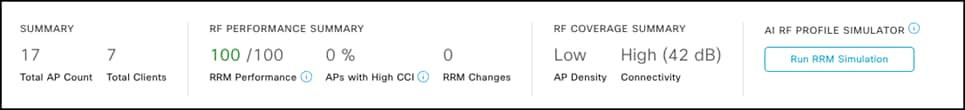
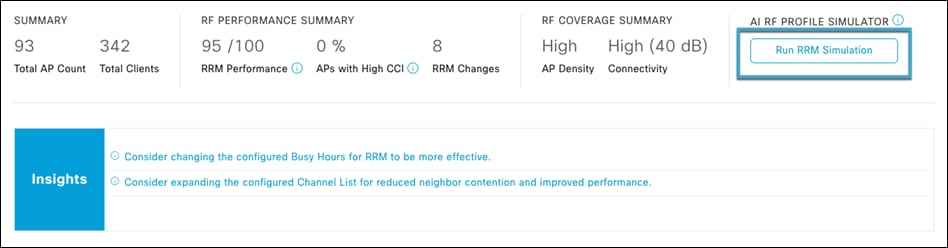
Summary Bar / Headlines
Below are the headlines regarding the RF Coverage and performance, which includes the overall RRM Performance score (100-0, with 100 being excellent) as well as highlights such as % APs with poor Co-channel Interference and count of RRM changes being made. The RRM Coverage summary looks at the AP density (the number of AP neighbors seen at or above -70 dBm) and Connectivity – the average client SNR during the last RRM run.
The calculation for the Neighbor Density Metric (NDM) is as follows:
NDM is determined by counting the total number of 'strong' neighbors, which are defined as neighboring devices with a Received Signal Strength Indicator (RSSI) greater than -70.
The categorization of Radio Frequency (RF) density is based on the average NDM and is classified in the following manner:
● Very High: The average NDM is greater than 15.
● High: The average NDM is greater than 10 but less than or equal to 15.
● Medium: The average NDM is greater than 5 but less than or equal to 10.
● Low: The average NDM is less than or equal to 5.
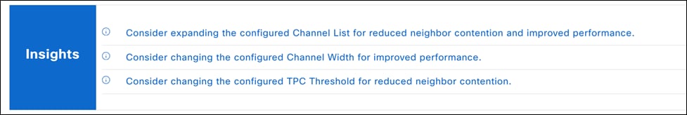
One way that AI-Enhanced RRM truly distinguishes itself from Cisco’s already powerful industry-leading RRM is the AI and ML components, along with the ability to store and use historical telemetry data and establish “normal” for a given observation over time. RRM on the controller has always been limited to viewing the current conditions as the data storage requirements were quite high.
Insights displayed here may be blank initially but will populate after an initial week of learning. AI will look at multiple aspects of the configuration and measure against the performance. One example of learned data is the Busy Hour configuration initially set in the AI RF Profile. learnings. The initial “Busy Hours” was configured when the AI RF Profile was created and assigned. Over time, and with clients on the network, AI-Enhanced RRM observes what when busy hours (when the network is under load) occur and may suggest an enhancement to the AI RF Profile. Selecting the insight test – will lead you to where the configuration can be changed. The administrator always has control of when to re-deploy/Assign the changed profile to the site. AI will provide insights on Tx Power, Channel Bandwidth, DCA settings, AP density, SNR etc.
Note: If you are overlapping RF Tags across sites, you will not be allowed to apply the insights to the AI-RF Profile. This will cause RF Tag level changes which is shared across sites. Recommendation here is to create a new RF Tag for the site with insights and then apply it after. A workaround will be to use the insight recommendation and manually making changes to the AI-RF profile which will also affect other sites sharing the same RF Tag.
Note: For busy hour insight to be generated, there will need to be a difference of at least 5 clients between min and max clients – and there must be traffic on the network – sleeping clients do not count.
In the next section, each of the performance metrics from the headlines is broken out into useful widgets, which let you explore the context of each down to the contributing radios/APs making up each component.
Note: The RF Performance matrix will not show radios if they are powered down or in power save mode.

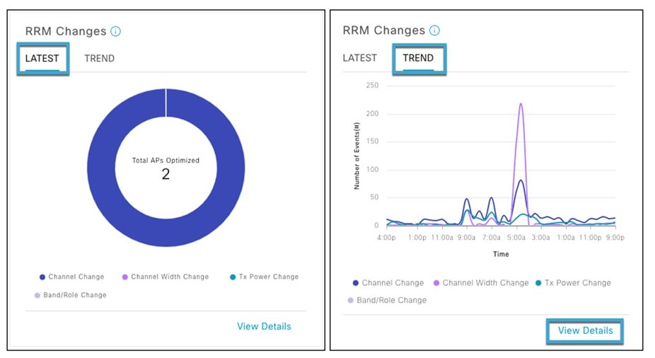
RRM Changes
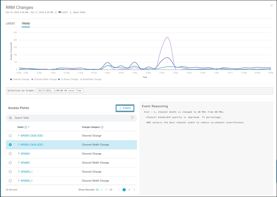
In AI-Enhanced RRM, “Latest” always shows the current 30-minute AI-Enhanced RRM run period results. As such, on a small network (this one has 5 APs total) there may not be any changes in the last reporting period so “0”. Trend shows the full span for the currently selected time (24 hours, 7 or 14 days) and allows the cursor to focus on a specific time in the chart to see how many of what kind of change was made. Selecting view details further expands the selection to include the APs that were affected, and selecting an AP shows the actions taken in the RRM change.
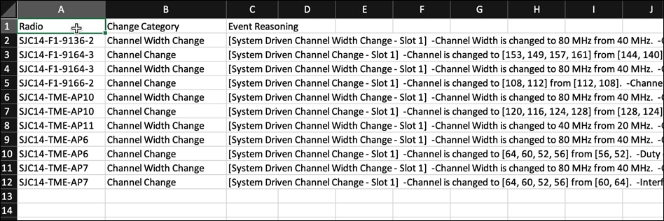
You can export the RRM changes into a CSV file and review it.
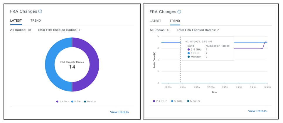
FRA Changes
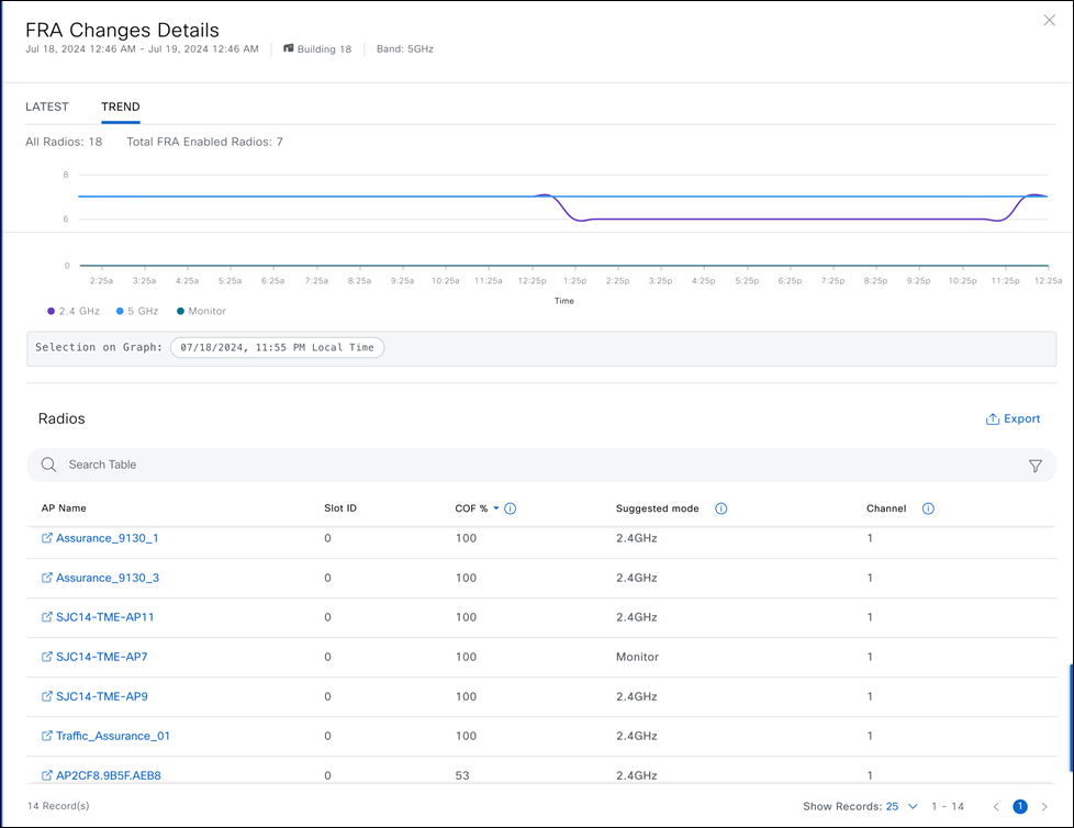
FRA changes widget lists down all FRA capable radios and their current operation mode which is 2.4 GHz/5GHz/Monitor. This widget is only available in 2.4 and 5GHz bands. When selecting trend view, it shows all the FRA changes in a timelapse view. View details will list out all the Access points with their different slot IDs, Coverage overlap factor %, suggested mode and current channel the radio is operating on.
Coverage Overlap Factor – output of FRA algorithm, represents percentage of 2.4 GHz cell covered to -67 dBm by other 2.4 GHz radios.
Cisco's FRA does 3 things:
● Calculates and maintains a measurement of redundancy for 2.4 GHz radios and represents this as a new measurement metric called COF (Coverage Overlap Factor).
● Manages radio “role” assignment or re- assignment for interfaces that are marked as redundant interfaces
● For Macro/Micro implementations FRA Manages Client load balancing across dual 5 GHz interfaces)
FRA decisions are made depending on the Coverage Overlap Factor % of each AP. The threshold for COF changes depending on busy hour sensitivity in the AI RF profile as shown below.
Busy hour sensitivity with respective to COF %:
Low Sensitivity: 100% COF
Medium Sensitivity: 95% COF
High Sensitivity: 90% COF
After busy hour: 90% COF
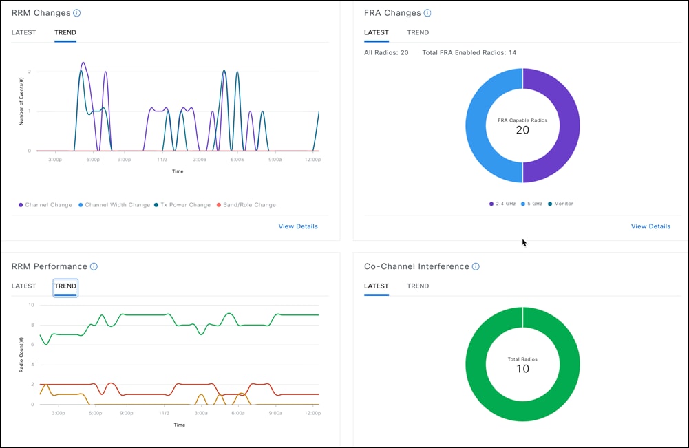
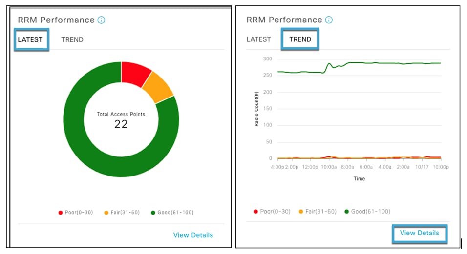
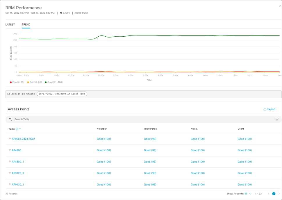
RRM Performance
RRM Performance tracks the performance score and how it changes over time. RRM Performance consists of multiple scores measuring co-channel, near-channel interference, and duty cycle. The default latest view shows the results as of the last RRM run (30 minutes). Trend displays a trend line and transitions for all APs contributing to the scores and allows selection of a specific point in time, which then displays the information – and details shows all the AP’s included in the score at any point in time. Note the export button, which will send any of the chart’s data to a CSV file for download. Selecting any Access point cross-links to the Device 360 view to further investigate the APs history and behavior.
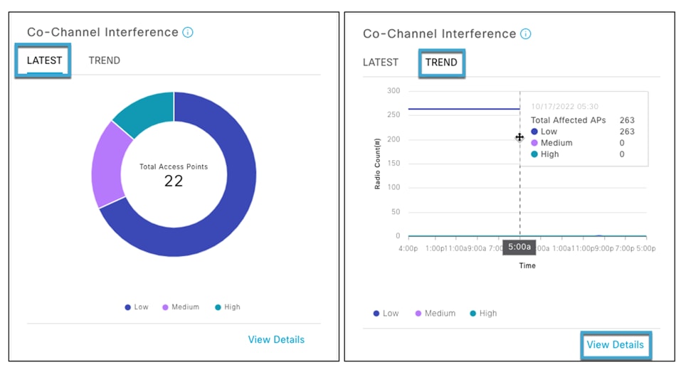
Co-Channel Interference
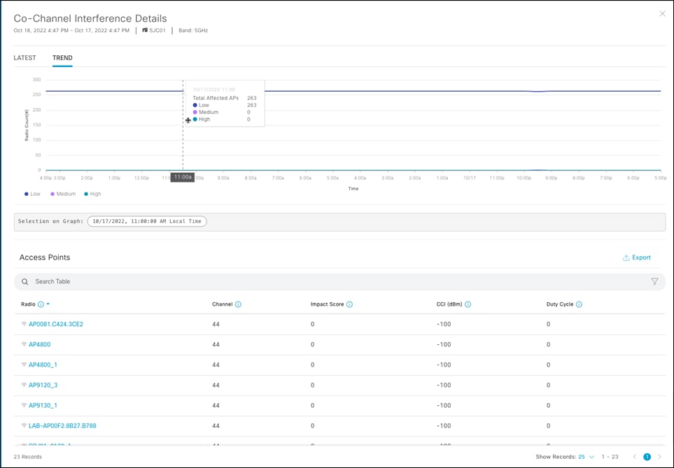
The Co-Channel interference widget follows the same pattern, showing the Latest Data from the last 30-minute interval and Trend which details the channel currently in use, an Impact Score (based on the duty cycle and RF Distance of co-channel neighbors) the CCI values in dBm and Channel Duty cycle (at that point in time)
CCI impact score = 100 - Co-Channel neighbor score
CCI Impact score ranges from 0-100, where the scores are categorized as:
● 0-40 = Low
● 41-70 = Med
● 71-100 = High
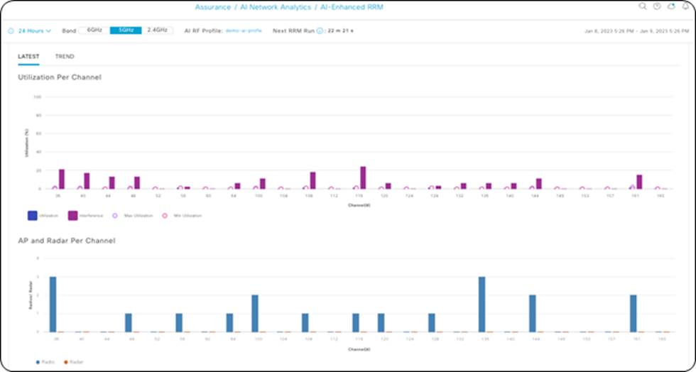
Utilization per Channel and AP Radios per Channel
The features "Utilization Per Channel" and "AP Radios Per Channel" provide a visual representation of the distribution and efficiency of access point (AP) radio deployment across the available wireless spectrum. These tools are critical for network administrators to evaluate whether AP radios are well-allocated, minimizing co-channel interference and optimizing network performance.
When APs are methodically dispersed across different channels, we anticipate a uniform pattern of channel utilization. This balanced spread ensures that each channel is used optimally, without excessive overlap that could lead to congestion and reduced throughput. It's the concept of "spatial reuse," where the same frequencies can be reused at different locations without causing interference, thereby maximizing the capacity of the wireless environment.
Cisco has conducted extensive testing to validate the effectiveness of AI-enhanced RRM. One such test involved initially configuring all APs to operate on the same channel. This scenario, which would typically lead to severe interference and poor network performance, serves as a stress test for the AI-Enhanced RRM system. Over the course of an hour or so, the AI-Enhanced RRM algorithm actively redistributed the APs across the spectrum. The result? The APs were automatically reassigned to different channels, leading to a more efficient use of the spectrum, as indicated by the even distribution in the post-test charts.
This kind of intelligent, automated channel management is particularly beneficial in dynamic environments where network conditions can change rapidly. Instead of relying on manual adjustments, network administrators can trust AI-Enhanced RRM to continuously analyze and optimize the radio frequency assignments, ensuring that the network can adapt to varying demands and maintain high performance.
The inclusion of a trend function enhances this feature by allowing users to review historical data on channel utilization over a specified period, which can extend up to two weeks. This historical data is valuable for identifying patterns in network usage, such as peak hours or days when the network experiences the most traffic.
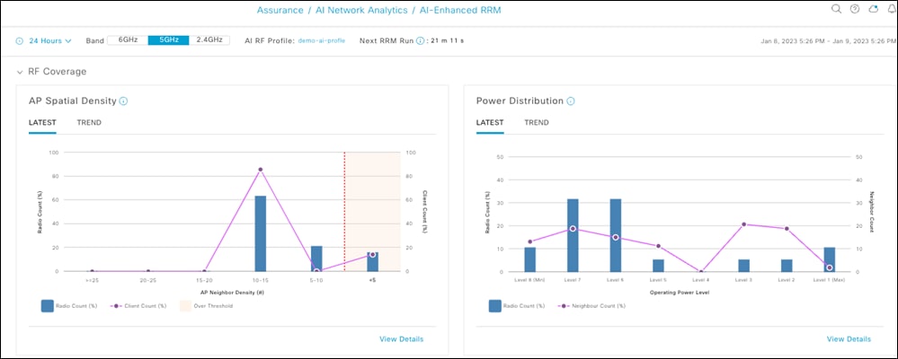
RF Coverage
The full RRM Control Center view. AP Spatial Density visualizes Neighboring AP/radio density in the RF neighborhood as the number of neighbors that can be seen at or above -70 dBm.
The Power Distribution Chart visualizes power distribution across the networks and provides a corresponding neighbor count to correlate AP density with power assignments. Trend allows visualization of history for up to two weeks. Selecting a time on the trend line opens the details for that point in time and lists the contributing APs.
Lower AP Spatial Density indicates fewer neighbors, which eventually leads to more APs with higher Power Levels. Similarly, more AP Neighbor density leads to lower Average Operational Power level on Aps.
RRM Simulator
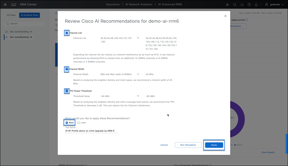
The RRM Simulator enables the network operator to preview the impact of RRM changes on the live network. When Cisco Catalyst Center recommends RRM setting changes through insights, or when the network administrator plans changes to settings such as channel, channel width, and power, the network administrator will be able to:
● Simulate how the RF environment will respond to recommended changes
● Analyze the impact of potential changes during a particular time interval
● View the proposed changes measured in quantified statistics, including RRM health, co-channel interference and utilization, and RRM changes
To use this feature on the Cisco Catalyst Center, go to the AI-Enhanced RRM control center from the Hamburger menu > Assurance > AI-Enhanced RRM > Select your site where you want to try these changes using RRM Simulator > Select the Band on the top on the control center > Click Run RRM Simulator from the Hero bar.
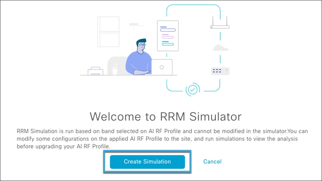
Click on Create Simulation from the Welcome to RRM Simulator page.
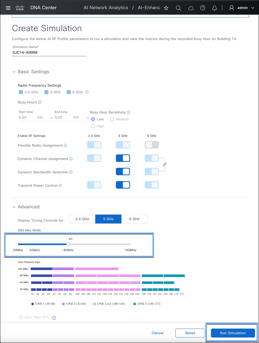
Make the changes necessary to the simulation profile which you need to analyze for a specific band (supported for only 1 band at a time).
In this case, we will change the DBS from 40 MHz to 80 MHz
Click Run Simulation to simulate RF performance data for the newly modified RF settings.
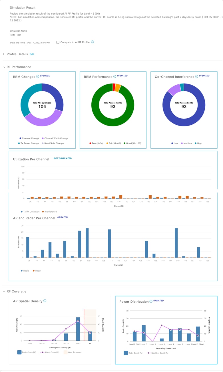
Step 4:
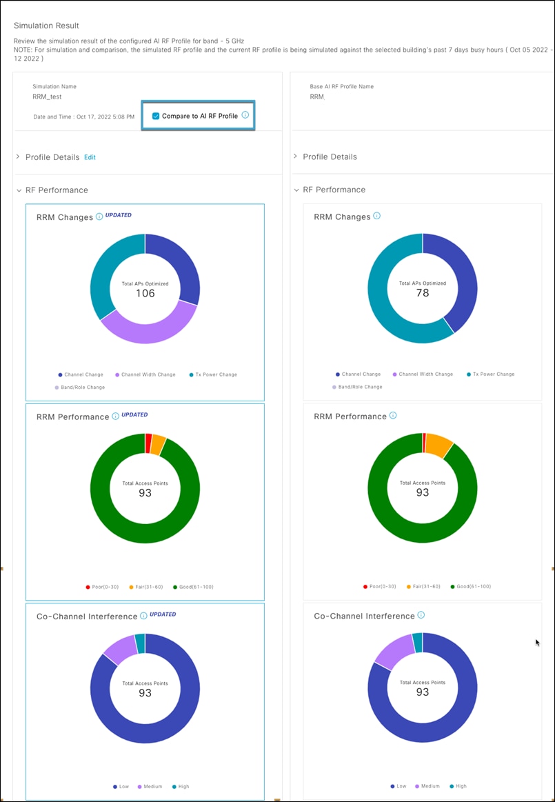
Simulation result is displayed as shown in the figure below. All the widgets tagged as UPDATED have changed after the RF settings modification. You can compare the simulated RF performance data with your current RF Performance data by selecting the Compare to AI RF Profile check box.
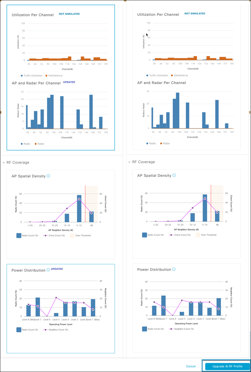
You can compare all the Widgets between the simulation and deployed AI RF profile for this site. The comparison is shown below. You can select Upgrade AI RF Profile if you wish to add these changes to the current AI-RF Profile. You can select cancel if you do not wish to make the changes to the AI RF Profile.
Day N: Making changes to AI RF Profile
When it comes to making changes to deployed AI RF Profile, there are 2 ways of doing it,
Step 1: Make changes to the AI-RF profile.
4. Selecting the AI RF profile hyperlink from the AI-Enhanced RRM control center page
5. Applying Insights from the control center (As Shown in the Insights section of Day-1 AI-Enhanced RRM features and use cases)
6. Using RRM simulator and selecting Upgrade AI RF Profile (As Shown in the RRM Simulator section of Day-1 AI-Enhanced RRM features and use cases)
7. Making changes through the Network settings page
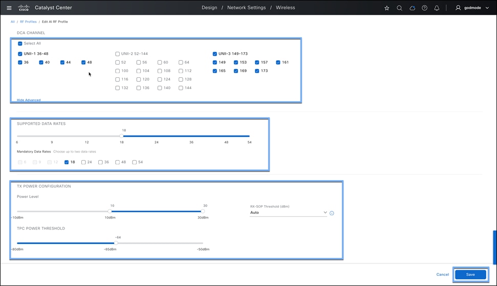
a. Click the hamburger menu icon and choose Design > Network Settings > Wireless Tab > Global > select RF Profiles Thumbnail > Select AI RF Profile tab > Click the check box of the AI RF Profile you want to edit and click edit.
b. Make changes to the AI RF Profile and hit save.
Note: Any changes to Basic Settings or Channel Width in AI RF Profile do not need Steps 2 and 3.
Step 2: This step is necessary if any change is made to the Advanced section in AI RF Profile
To assign this AI RF Profile to a site, on your AI RF Profile column, click on (…), then go to Assign location.
At this step, the workflow will take you back to Part 4a: AI-Enhanced RRM Workflow for v2.3.7.4 and above > Step 2
Disable AI-Enhanced RRM: Unassign AI RF Profile
This workflow will disable AI-Enhanced RRM in your Catalyst 9800 Wireless controller. This will move your RF group leader back to the WLC.
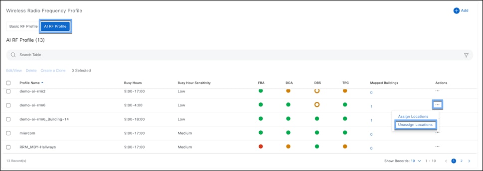
Click the hamburger menu icon and choose Design > Network Settings > Wireless Tab > Global > select RF Profiles Thumbnail > Select AI RF Profile tab.
To unassign this AI RF Profile from a site, on your AI RF Profile column, click on (…), then go to Unassign location.
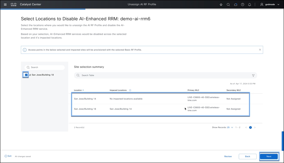
Step 3:
Select the buildings as part of the AI RF profile.
In this step, all impacted buildings will be automatically selected which as part of the same 9800 Wireless Controller.

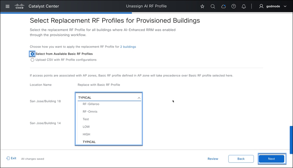
For Device Provisioning deployment:
Option 1:
Select a Basic RF Profile available from Network settings.
Option 2:
Upload RF_profile_backup from Part 4a: AI-Enhanced RRM Workflow > Step 8.
For without Device Provisioning deployment:
Option 1:
Disable AI-Enhanced RRM by keeping the same RF profile settings.
This step will only disable RF grouping and keep all the RF Profile settings as is in the Catalyst 9800 Wireless Controller
Option 2:
Upload RF_profile_backup from Part 4a: AI-Enhanced RRM Workflow > Step 8
Step 5:
Go through summary and apply the configurations.
Verify RF group leader in Catalyst 9800 Wireless Controller as the controller itself.
Cisco Catalyst Center User Guide, Release 2.3.7
Cisco Catalyst Center Information
Cisco Catalyst 9800 Information
https://www.cisco.com/c/en/us/products/wireless/catalyst-9800-series-wireless-controllers/index.html
Cisco Catalyst 9100 Information
https://www.cisco.com/c/en/us/products/wireless/catalyst-9100ax-access-points/index.html
Useful Videos
Cisco AI-Enhanced RRM: The Next Chapter in RF Performance
https://www.youtube.com/watch?v=-ImLXmS7n8c
Unleash the power of AI in Wi-Fi with Cisco's AI-Enhanced RRM: How to Demo
https://www.youtube.com/watch?v=fVzrfb1wi9g&t=9s
Cisco and the Cisco logo are trademarks or registered trademarks of Cisco and/or its affiliates in the U.S. and other countries. To view a list of Cisco trademarks, go to this URL: www.cisco.com/go/trademarks. Third-party trademarks mentioned are the property of their respective owners. The use of the word partner does not imply a partnership relationship between Cisco and any other company. (1110R)
Any Internet Protocol (IP) addresses and phone numbers used in this document are not intended to be actual addresses and phone numbers. Any examples, command display output, network topology diagrams, and other figures included in the document are shown for illustrative purposes only. Any use of actual IP addresses or phone numbers in illustrative content is unintentional and coincidental.
© 2025 Cisco Systems, Inc. All rights reserved.