Cisco QSFP-100G-ZR4-S Pluggable Transceiver At-a-Glance
Available Languages
Bias-Free Language
The documentation set for this product strives to use bias-free language. For the purposes of this documentation set, bias-free is defined as language that does not imply discrimination based on age, disability, gender, racial identity, ethnic identity, sexual orientation, socioeconomic status, and intersectionality. Exceptions may be present in the documentation due to language that is hardcoded in the user interfaces of the product software, language used based on RFP documentation, or language that is used by a referenced third-party product. Learn more about how Cisco is using Inclusive Language.
Extended reach links for 100Gb
Whether it’s a new build or an upgrade of an existing network, the Cisco QSFP-100G-ZR4-S transceiver provides 100G connectivity for platforms located up to 80 km apart on SMF (Single-Mode Fiber).
As network traffic continues to grow driven by increases in wireless and wireline usage, the demand for 100Gb transceivers is needed at a variety of reaches. While Cisco has an existing portfolio of QSFP-100G transceivers for SMF for 500 m, 2 km, 10 km, 25 km, 30 km, and 40 km reaches, the QSFP-100G-ZR4-S transceiver now adds 80 km reach, as shown in figure 2.
The QSFP-100G-ZR4-S enables 100Gb at distances reaching 80km to connecting: wireless access locations to core networks, distant enterprise locations to each other, widely separated regional data centers together, or remote service provider buildings to central offices.
QSFP-100G-ZR4
● Connect sites up to 80km apart with 100G links
● Leverages the QSFP 28 ports in existing platforms
● Integrated SOA enables up to 80km reach without requiring an external amplifier
● Cost-effective solution for space and power constrained locations
● Supported across multiple Cisco routing and switching platforms
● Use cases include Service Provider, Data Center and Enterprise needing long reach connectivity
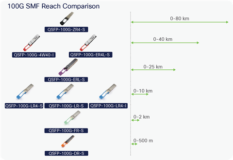
Reach comparison of Cisco QSFP-100G SMF transceivers
Applications today requiring QSFP-100G-ZR4-S include:
● Wireless: aggregating 4G and 5G fronthaul and midhaul routers
● Service provider: reaching rural and remote COs
● Data center: connecting regional centers
● Enterprise: linking metro offices
A typical installation involving QSFP-100G-ZR4-S might include switches or routers as shown in Figure 3.
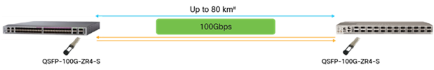
Application requiring QSFP-100G-ZR4
Existing options for 100G connectivity reaching 80km are primarily based on specific chassis, line cards, or large modules. As a result, these solutions tend to require lots of power or take up large amounts of space, resulting in higher costs to deploy and operate. The Cisco QSFP-100G-ZR4-S solution operates with relatively low power and the modules fit into standard QSFP28 ports, resulting in a cost effective solution.
The QSFP-100G-ZR4-S operates in the O-band optical spectrum where fiber optic dispersion is minimal, using traditional direct-detect transceiver technology with NRZ (Nonreturn to Zero) modulation. A SOA (Semiconductor Optical Amplifier) is used to overcome the optical attenuation of the long reach. The lasers in the QSFP-100G-ZR4-S leverage the traditional LAN WDM grid lasers found in other QSFP-100G transceivers. As like many other QSFP28 transceivers, the QSFP-100G-ZR4 has 4 optical and electrical lanes, where each lane is operating at 25Gb. The block diagram in Figure 4, shows the transmit signal of the QSFP-100G-ZR4-S consisting of four lasers each operating at a different wavelength that are muxed into a single optical fiber, and on another fiber in the receive path the optical signal is amplified by an SOA and then demuxed in 4 unique wavelengths and fed into four receivers.
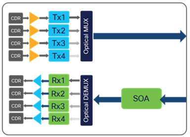
Block diagram of QSFP-100G-ZR4-S
Summary of QSFP-100G-ZR4-S specifications
Table 1. QSFP-100G-ZR4-S specification summary
| PID |
QSFP-100G-ZR4-S |
| Data Rate |
100G |
| Reach |
0-80 km# |
| Fiber |
SMF |
| Wavelengths |
1296, 1300, 1304, and 1309 nm |
| Max Power |
5.5W |
| Optical Connector |
Duplex-LC |
| Pull Tab Color |
Black |
| Required Host FEC |
RS-FEC |
| DOM |
Yes |
| Coding |
NRZ |
| Form Factor |
QSFP28 |
| Operating Temp |
0 to 70°C |
Detailed specifications for the QSFP-100G-ZR4-S can be found at Cisco Optics Product Information: https://copi.cisco.com/
# Depends upon fiber and connector loss
The QSFP-100G-ZR4-S requires Host- Based RS-FEC (Reed Solomon Forward Error Correction) and provides DOM (Digital Optical Monitoring) to provide important optical-level information.
Since the QSFP-100G-ZR4-S requires up to 5.5W over its full commercial temperature range of 0 to 70°C, which is higher powered than many traditional 3.5W QSFP28 transceivers, power supply and cooling/ thermal verification is performed on Cisco platforms where it is used.
The configurations and software required to operate in Cisco platforms can be found in Cisco’s Optics-to-Device Compatibility Matrix: https://tmgmatrix.cisco.com/
To determine the interoperability of the QSFP-100G-ZR4-S with other Cisco transceivers, please see Cisco’s Optics-to-Optics Compatibility Matrix: https://tmgmatrix.cisco.com/iop