Cisco MDS 9000 Family Fabric Manager Configuration Guide, Release 2.x
IPsec and IKE

Table Of Contents

IPsec and IKE

Configuring IPsec Network Security

The 14/2-Port Multiprotocol Services Module

IPsec Prerequisites

IPsec Compatibility

About IPsec

About IKE

IPsec and IKE Terminology

Supported IPsec Transforms

Supported IKE Transforms and Algorithms

Supported Algorithms for Windows and Linux Platforms

Enabling IPsec Using FCIP Wizard

Modifying IKE and IPsec

Crypto ACL Guidelines

Mirror Image Crypto ACLs

The any Keyword in Crypto ACLs

Configuring Crypto IP-ACLs

Transform Sets

Crypto Map Entries

SA Establishment Between Peers

The AutoPeer Option

SA Lifetime Negotiation

Perfect Forwarding Secrecy

Creating or Modifying Crypto Maps

Applying a Crypto Map Set to an Interface

IPsec Maintenance

Global Lifetime Values


IPsec and IKE


Fabric Manager provides the capability to configure and manage IPsec using IKE.

This chapter includes the following sections:

Configuring IPsec Network Security

Enabling IPsec Using FCIP Wizard

Modifying IKE and IPsec

Configuring IPsec Network Security

IP Security Protocol (IPsec) is a framework of open standards that provides data confidentiality, data integrity, and data authentication between participating peers. It is developed by the Internet Engineering Task Force (IETF). IPsec provides these security services at the IP layer. IPsec can be used to protect one or more data flows between a pair of hosts, between a pair of security gateways, or between a security gateway and a host. The overall IPsec implementation is per the latest version of RFC2401. Cisco SAN-OS IPsec implements RFC 2402 through RFC 2410.

Refer to the following website for further information on the IPsec RFCs:
http://www.ietf.org.

IPsec uses the Internet Key Exchange (IKE) protocol to handle protocol and algorithm negotiation and to generate the encryption and authentication keys to be used by IPsec. While IKE can be used with other protocols, its initial implementation is with the IPsec protocol. IKE provides authentication of the IPsec peers, negotiates IPsec security associations, and establishes IPsec keys. IKE uses RFCs 2408, 2409, 2410, and additionally, implements the draft-ietf-ipsec-ikev2-15.txt draft.

Refer to the following website for further information on the IKE draft:
http://www.ietf.org/


Note The term IPsec is sometimes used to describe the entire protocol of IPsec data services and IKE security protocols and is also sometimes used to describe only the data services.


The 14/2-Port Multiprotocol Services Module

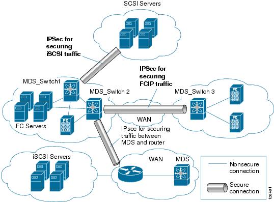
The 14/2-port Multiprotocol Services (MPS-14/2) module allows you to use Fibre Channel, FCIP, and iSCSI features. It integrates seamlessly into the Cisco MDS 9000 Family, and it supports the full range of features available on other switching modules, including VSANs, security, and traffic management.

This module is available for use in any switch in the Cisco MDS 9200 Series or in the Cisco MDS 9500 Series. The 16-port, hot-swappable MPS-14/2 module has 14 Fibre Channel ports (numbered 1 through 14) and two Gigabit Ethernet ports (numbered 1 and 2) that can support FCIP protocol, iSCSI protocol, or both protocols simultaneously. The MPS-14/2 supports IPsec on the Gigabit Ethernet ports. See the "Enabling IPsec Using FCIP Wizard" section.

Figure 29-1 shows how the MPS-14/2 module is used in different scenarios.

Figure 29-1 FCIP and iSCSI Scenarios Using MPS-14-2 Modules

IPsec Prerequisites

To use the IPsec feature, you need to perform the following tasks:

Obtain the ENTERPRISE_PKG license.

Configure IKE.


Note The IPsec feature inserts new headers in existing packets.


IPsec Compatibility

IPsec features are compatible with the following Cisco MDS hardware running Cisco MDS SAN-OS Release 2.0 or later:

MPS-14/2 modules in Cisco MDS 9200 Switches or Cisco MDS 9500 Directors

Cisco MDS 9216i Switch with the 14/2-Port multiprotocol capability in the integrated supervisor module. Refer to the Cisco MDS 9200 Series Hardware Installation Guide for more information on the Cisco MDS 9216i Switch.


Note In both the MPS module and the Cisco MDS 9216i integrated supervisor module, the port numbering differs for the Fibre Channel and the Gigabit Ethernet ports—the Fibre Channel ports are numbered from 1 through 14 and the Gigabit Ethernet ports are numbered as 1 and 2.


IPsec features are compatible with the following fabric set up:

Two connected Cisco MDS 9200 switches or Cisco MDS 9500 directors running Cisco MDS SAN-OS Release 2.0 or later.

Cisco MDS 9200 switches or Cisco MDS 9500 directors running Cisco MDS SAN-OS Release 2.0 or later connected to any Cisco router.

Cisco MDS 9200 switches or Cisco MDS 9500 directors running Cisco MDS SAN-OS Release 2.0 or later connected to any Cisco host.

The following features are not supported in the SAN-OS implementation of the IPsec feature:

Authentication header (AH).

Transport mode.

Security association bundling.

Manually configuring security associations.

Per host security association option in a crypto map.

Security association idle timeout

Dynamic crypto maps.


Note Any reference to crypto maps in this document, only refers to static crypto maps.


About IPsec

IPsec provides security for transmission of sensitive information over unprotected networks such as the Internet. IPsec acts at the network layer, protecting and authenticating IP packets between participating IPsec devices (peers).

IPsec provides the following network security services. In general, the local security policy dictates the use of one or more of these services between two participating IPsec switches:

Data confidentiality—The IPsec sender can encrypt packets before transmitting them across a network.

Data integrity—The IPsec receiver can authenticate packets sent by the IPsec sender to ensure that the data has not been altered during transmission.

Data origin authentication—The IPsec receiver can authenticate the source of the IPsec packets sent. This service is dependent upon the data integrity service.

Anti-replay protection—The IPsec receiver can detect and reject replayed packets.


Note The term data authentication is generally used to mean data integrity and data origin authentication. Within this chapter it also includes anti-replay services, unless otherwise specified.


With IPsec, data can be transmitted across a public network without fear of observation, modification, or spoofing. This enables applications such as Virtual Private Networks (VPNs), including intranets, extranets, and remote user access.

IPsec as implemented in Cisco SAN-OS software supports the Encapsulating Security Payload (ESP) protocol. This protocol encapsulates the data to be protected and provides data privacy services, optional data authentication, and optional anti-replay services.


Note The Encapsulating Security Payload (ESP) protocol is a header inserted into an existing TCP/IP packet, the size of which depends on the actual encryption and authentication algorithms negotiated. To avoid fragmentation, the encrypted packet fits into the interface maximum transmission unit (MTU). The path MTU calculation for TCP takes into account the addition of ESP headers, plus the outer IP header in tunnel mode, for encryption. The MDS switches allow 100 bytes for packet growth for IPsec encryption


About IKE

IKE automatically negotiates IPsec security associations and generates keys for all switches using the IPsec feature. Specifically, IKE provides these benefits:

Allows you to refresh IPsec SAs.

Allows IPsec to provide anti-replay services.

Supports a manageable, scalable IPsec configuration.

Allows dynamic authentication of peers.

Two versions of IKE are used in the SAN-OS implementation: IKE version 1 (IKEv1) and IKE version 2.

IPsec and IKE Terminology

The terms used in this chapter are explained in this section.

Security association (SA)— An agreement between two participating peers on the entries required to encrypt and decrypt IP packets. Two SAs are required for each peer in each direction (inbound and outbound) to establish bidirectional communication between the peers. Sets of bidirectional SA records are stored in the SA database (SAD). IPsec uses IKE to negotiate and bring up SAs. Each SA record includes the following information:

Security parameter index (SPI)—A number which, together with a destination IP address and security protocol, uniquely identifies a particular SA. When using IKE to establish the SAs, the SPI for each SA is a pseudo-randomly derived number.

Peer—A switch or other device that participates in IPsec. For example, a Cisco MDS switch or other Cisco routers that support IPsec.

Transform—A list of operations done on a dataflow to provide data authentication, data confidentiality, and data compression. For example, one transform is the ESP protocol with the HMAC-MD5 authentication algorithm.

Session keys—A key to encrypt and decrypt IP packets in a specified IKE session.

Lifetime—A lifetime counter (in seconds and bytes) is maintained from the time the SA is created. When the time limit expires the SA is no longer operational and is automatically renegotiated (rekeyed).

Mode of operation—Two modes of operation are generally available for IPsec and IKE: tunnel mode and transport mode. The SAN-OS implementation of IPsec only supports the tunnel mode. The IPsec tunnel mode encrypts and authenticates the IP packet and an additional IP header between two hosts, a host and a gateway, or between two gateways. The gateways encrypt traffic on behalf of the hosts and subnets. This mode implements secure internal, external, remote access, and other networks. The SAN-OS implementation of IPsec does not support transport mode.


Note The term tunnel mode is different from the term tunnel used to indicate secure communication path between two peers, such as two switches connected by an FCIP link.


Anti-replay—A security service where the receiver can reject old or duplicate packets in order to protect itself against replay attacks. IPsec provides this optional service by use of a sequence number combined with the use of data authentication.

Data authentication—Data authentication can refer either to integrity alone or to both integrity and authentication (data origin authentication is dependent on data integrity).

Data integrity—Verifies that data has not been altered.

Data origin authentication—Verifies that the data was actually sent by the claimed sender.

Data confidentiality—A security service where the protected data cannot be observed.

Data flow—A grouping of traffic, identified by a combination of source address/mask, destination address/mask, IP next protocol field, and source and destination ports, where the protocol and port fields can have the values of any. Traffic matching a specific combination of these values is logically grouped together into a data flow. A data flow can represent a single TCP connection between two hosts, or it can represent traffic between two subnets. IPsec protection is applied to data flows.

Perfect forwarding secrecy (PFS)—A cryptographic characteristic associated with a derived shared secret value. With PFS, if one key is compromised, previous and subsequent keys are not compromised, because subsequent keys are not derived from previous keys.

Security Policy Database (SPD)—an ordered list of policies applied to traffic. A policy decides if a packet requires IPsec processing, if should be allowed in clear text, or if it should be dropped.

IPsec SPDs are derived from user configuration of crypto maps.

IKE SPDs are configured by the user.

Supported IPsec Transforms

The component technologies implemented for IPsec include the following transforms:

Advanced Encrypted Standard (AES) is an encryption algorithm. It implements either 128 or 256 bits using Cipher Block Chaining (CBC) or counter mode. This is an encryption technology.

Data Encryption Standard (DES) is used to encrypt packet data and implements the mandatory 56-bit DES-CBC. CBC requires an initialization vector (IV) to start encryption. The IV is explicitly given in the IPsec packet. This is an encryption technology.

Triple DES (3DES) is a strong form of encryption that allows sensitive information to be transmitted over untrusted networks. It enables customers to utilize network layer encryption and implements 168-bit encryption. This is an encryption technology.


Note Cisco SAN-OS images with strong encryption are subject to United States government export controls, and have a limited distribution. Images to be installed outside the United States require an export license. Customer orders might be denied or subject to delay due to United States government regulations. Contact your sales representative or distributor for more information, or send e-mail to export@cisco.com.


Message Digest 5 (MD5) is a hash algorithm with the HMAC variant. HMAC is a keyed hash variant used to authenticate data. This is an authentication technology.

Secure Hash Algorithm (SHA-1) is a hash algorithm with the Hash Message Authentication Code (HMAC) variant. This is an authentication technology.

AES-XCBC-MAC is a Message Authentication Code (MAC) using the AES algorithm. This is an authentication technology.

Supported IKE Transforms and Algorithms

The component technologies implemented for IKE include the following transforms:

Diffie-Hellman (DH) is a public-key cryptography protocol which allows two parties to establish a shared secret over an unsecure communications channel. Diffie-Hellman is used within IKE to establish session keys. Group 1 (768-bit), Group 2 (1024-bit), and Group 5 (1536-bit) groups are supported.

Advanced Encrypted Standard (AES) is an encryption algorithm. It implements either 128 bits using Cipher Block Chaining (CBC) or counter mode. This is an encryption technology.

Data Encryption Standard (DES) is used to encrypt packet data and implements the mandatory 56-bit DES-CBC. CBC requires an initialization vector (IV) to start encryption. The IV is explicitly given in the IPsec packet. This is an encryption technology.

Triple DES (3DES) is a strong form of encryption that allows sensitive information to be transmitted over untrusted networks. It enables customers to utilize network layer encryption and implements 168-bit encryption. This is an encryption technology.


Note Cisco SAN-OS images with strong encryption are subject to United States government export controls, and have a limited distribution. Images to be installed outside the United States require an export license. Customer orders might be denied or subject to delay due to United States government regulations. Contact your sales representative or distributor for more information, or send e-mail to export@cisco.com.


Message Digest 5 (MD5) is a hash algorithm with the HMAC variant. HMAC is a keyed hash variant used to authenticate data. This is an authentication technology.

Secure Hash Algorithm (SHA-1) is a hash algorithm with the Hash Message Authentication Code (HMAC) variant. This is an authentication technology.

The switch authentication algorithm uses the preshared keys based on the IP address.

Supported Algorithms for Windows and Linux Platforms

Table 29-1 lists the supported and verified settings for IPSec and IKE encryption authentication algorithms on the Microsoft Windows and Linux platforms.

Table 29-1 Supported Algorithms for Windows and Linux Platforms

Platform
IKE
IPsec

Microsoft iSCSI initiator, Microsoft IPSec implementation on Microsoft Windows 2000 platform

3DES, SHA-1 or MD5,
DH group 2

3DES, SHA-1

Cisco iSCSI initiator,
Free Swan IPSec implementation on Linux platform

3DES, MD5, DH group 1

3DES, MD5


Enabling IPsec Using FCIP Wizard

Fabric Manager simplifies the configuration of IPsec and IKE by enabling and configuring these features as part of the FCIP configuration using the FCIP Wizard. See the "Using the FCIP Wizard" section on page 19-5.

To enable IPsec using Fabric Manager, follow these steps:
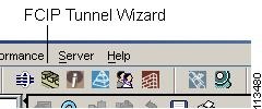

Step 1 Open the FCIP Wizard by clicking its icon in the Fabric Manager toolbar. Figure 29-2 shows the FCIP Wizard icon.

Figure 29-2 FCIP Wizard

Step 2 Choose the switches that act as endpoints for the FCIP link and click Next.


Note These switches must have MPS-14/2 modules installed to configure IPsec on this FCIP link.


Step 3 Choose the Gigabit Ethernet ports on each MPS-14/2 module that will form the FCIP link.

Step 4 Check the Enforce IPSEC Security check box and set Ike Auth Key as shown in Figure 29-3.

Figure 29-3 Enabling IPsec on an FCIP Link

Step 5 Click Next. You see the TCP connection characteristics.

Step 6 Set the minimum and maximum bandwidth settings and round-trip time for the TCP connections on this FCIP link. You can measure the round-trip time between the Gigabit Ethernet endpoints by clicking the Measure button.

Step 7 Check the Enable Write Acceleration check box to enable FCIP write acceleration on this FCIP link. See the " FCIP Write Acceleration" section on page 19-4.

Step 8 Check the Enable Optimum Compression check box to enable IP compression on this FCIP link. See the "FCIP Compression" section on page 19-5.

Step 9 Click Next to configure the FCIP tunnel parameters.

Step 10 Set the Port VSAN and click the Trunk Mode radio button for this FCIP link. See the "Checking Trunk Status" section on page 19-10.

Step 11 Click Finish to create this FCIP link or click Cancel to exit the FCIP Wizard without creating an FCIP link.


Modifying IKE and IPsec

Once IPsec is configured on an FCIP link, you can modify IKE and IPsec features using Fabric Manager. IKE must first be enabled and configured so the IPsec feature can trigger an SA with the required peer.

You cannot disable IKE if IPsec is enabled. When you disable the IKE feature, the IPsec configuration is cleared from the running configuration.

To verify that IPsec and IKE are enabled using Fabric Manager, follow these steps:


Step 1 Choose Switches > Security > IPSEC in the Physical Attributes pane. You see the IPsec configuration in the Information pane.

Step 2 Choose the Control tab and verify that the switches you want to modify for IPsec are enabled in the Status column.

Step 3 Choose Switches > Security > IKE in the Physical Attributes pane. You see the IKE configuration in the Information pane.

Step 4 Choose the Control tab and verify that the switches you want to modify for IKE are enabled in the Status column.


Crypto ACL Guidelines

Follow these guidelines when configuring ACLs for the IPsec feature:

The permit option causes all IP traffic that matches the specified conditions to be protected by crypto, using the policy described by the corresponding crypto map entry.

The deny option prevents traffic from being protected by crypto. The first deny statement causes the traffic to be in clear text.

The crypto ACL you define is applied to an interface after you define the corresponding crypto map entry and apply the crypto map set to the interface.

Different ACLs must be used in different entries of the same crypto map set.

Inbound and outbound traffic is evaluated against the same outbound IPsec ACL. Therefore, the ACL's criteria is applied in the forward direction to traffic exiting your switch, and the reverse direction to traffic entering your switch.

In Figure 29-4, IPsec protection is applied to traffic between Host 10.0.0.1 and Host 20.0.0.2 as the data exits switch A's S0 interface enroute to Host 20.0.0.2. For traffic from Host 10.0.0.1 to Host 20.0.0.2, the ACL entry on switch A is evaluated as follows:

source = host 10.0.0.1

dest = host 20.0.0.2

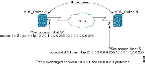
For traffic from Host 20.0.0.2 to Host 10.0.0.1, that same ACL entry on switch A is evaluated as follows:

source = host 20.0.0.2

dest = host 10.0.0.1

Figure 29-4 IPsec Processing of Crypto ACLS

If you configure multiple statements for a given crypto ACL which is used for IPsec, the first permit statement that is matched is used to determine the scope of the IPsec SA. Later, if traffic matches a different permit statement of the crypto ACL, a new, separate IPsec SA is negotiated to protect traffic matching the newly matched ACL statement.

Unprotected inbound traffic that matches a permit entry in the crypto ACL for a crypto map entry flagged as IPsec is dropped, because this traffic was expected to be protected by IPsec.

The IP ACLs used for traffic filtering purposes are also used for crypto.

Mirror Image Crypto ACLs

For every crypto ACL specified for a crypto map entry defined at the local peer, define a mirror image crypto ACL at the remote peer. This configuration ensures that IPsec traffic applied locally can be processed correctly at the remote peer.


Tip The crypto map entries themselves must also support common transforms and must refer to the other system as a peer.)


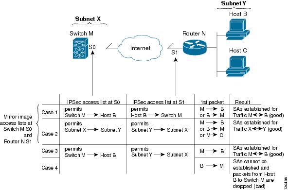
Figure 29-5 shows some sample scenarios with and without mirror image ACLs.

Figure 29-5 IPsec Processing of Mirror Image Configuration

As Figure 29-5 indicates, IPsec SAs can be established as expected whenever the two peers' crypto ACLs are mirror images of each other. However, an IPsec SA can be established only some of the time when the ACLs are not mirror images of each other. This can happen in the case where an entry in one peer's ACL is a subset of an entry in the other peer's ACL, such as shown in Cases 3 and 4 of Figure 3. IPsec SA establishment is critical to IPsec—without SAs, IPsec does not work, causing any packets matching the crypto ACL criteria to be silently dropped instead of being forwarded with IPsec security.

In Figure 29-5, an SA cannot be established in Case 4. This is because SAs are always requested according to the crypto ACLs at the initiating packet's end. In Case 4, switch N requests that all traffic between Subnet X and Subnet Y be protected, but this is a superset of the specific flows permitted by the crypto ACL at switch M so the request is therefore not permitted. Case 3 works because switch M's request is a subset of the specific flows permitted by the crypto ACL at switch N.

Because of the complexities introduced when crypto ACLs are not configured as mirror images at peer IPsec devices, Cisco strongly encourages you to use mirror image crypto ACLs.

The any Keyword in Crypto ACLs


Tip We recommend that you configure mirror image crypto ACLs for use by IPsec and that you avoid using the any option.


The any option in a permit statement is discouraged when you have multicast traffic flowing through the IPsec interface—this configuration can cause multicast traffic to fail.

The permit any any statement causes all outbound traffic to be protected (and all protected traffic sent to the peer specified in the corresponding crypto map entry) and requires protection for all inbound traffic. Then, all inbound packets that lack IPsec protection are silently dropped, including packets for routing protocols, NTP, echo, echo response, and so forth.

You need to be sure you define which packets to protect. If you must use the any option in a permit statement, you must preface that statement with a series of deny statements to filter out any traffic (that would otherwise fall within that permit statement) that you do not want to be protected.

Configuring Crypto IP-ACLs

You can configure IP-ACLs for crypto using the guidelines in the "Crypto ACL Guidelines" section.

See Chapter 28, "IP Access Control Lists" for guidelines on creating IP-ACLs using Fabric Manager.

Transform Sets

A transform set represents a certain combination of security protocols and algorithms. During the IPsec security association negotiation, the peers agree to use a particular transform set for protecting a particular data flow.

You can specify multiple transform sets, and then specify one or more of these transform sets in a crypto map entry. The transform set defined in the crypto map entry is used in the IPsec security association negotiation to protect the data flows specified by that crypto map entry's access list.

During IPsec security association negotiations with IKE, the peers search for a transform set that is the same at both peers. When such a transform set is found, it is selected and applied to the protected traffic as part of both peers' IPsec security associations.


Tip If you change a transform set definition, the change is only applied to crypto map entries that reference the transform set. The change is not applied to existing security associations, but used in subsequent negotiations to establish new security associations. If you want the new settings to take effect sooner, you can clear all or part of the security association database.


Table 29-2 provides a list of allowed transform combinations.

Table 29-2 Allowed Transform Combinations

Transform Type
Transform
Description

ESP encryption1 transform (pick one.)

esp-des

ESP with the 56-bit DES encryption algorithm

esp-3des

ESP with the 168-bit DES encryption algorithm (3DES or Triple DES)

aes-128

In both counter mode2 and CBC

aes-256

ESP authentication3 transform (pick one.)

esp-md5-hmac

ESP with the MD5 (HMAC variant) authentication algorithm

esp-sha-hmac

ESP with the SHA (HMAC variant) authentication algorithm

aes-xcbc-mac

AES SCBC (MAC variant) ESP authentication algorithm

1 Mandatory.

2 If you select counter mode ESP encryption, authentication is required.

3 Optional in all other encryption cases (except counter mode).


Crypto Map Entries

Once you have created the crypto ACLs, you can create crypto map sets to the interfaces. Crypto map IPsec entries pull together the various parts of the IPsec SA, including:

The traffic to be protected by IPsec (per the crypto ACL). A crypto map set can contain multiple entries, each with a different ACL.

The granularity of the flow to be protected by a set of SAs.

The IPsec-protected traffic destination (who the remote IPsec peer is).

The local address to be used for the IPsec traffic (applying to an interface).

The IPsec security to be applied to this traffic (selecting from a list of one or more transform sets)

Other parameters to define an IPsec SA

Crypto map entries with the same crypto map name (but different map sequence numbers) are grouped into a crypto map set.

When you apply a crypto map set to an interface, the following events occur:

A security policy database (SPD) is created for that interface

All IP traffic passing through the interface is evaluated against the SPD.

If a crypto map entry sees outbound IP traffic that requires protection, an SA is negotiated with the remote peer according to the parameters included in the crypto map entry.

The policy derived from the crypto map entries is used during the negotiation of SAs. If the local switch initiates the negotiation, it will use the policy specified in the crypto map entries to create the offer to be sent to the specified IPsec peer. If the IPsec peer initiates the negotiation, the local switch checks the policy from the crypto map entries and decide whether to accept or reject the peer's request (offer).

For IPsec to succeed between two IPsec peers, both peers' crypto map entries must contain compatible configuration statements.

SA Establishment Between Peers

When two peers try to establish an SA, they must each have at least one crypto map entry that is compatible with one of the other peer's crypto map entries.

For two crypto map entries to be compatible, they must at least meet the following criteria:

The crypto map entries must contain compatible crypto ACLs (for example, mirror image ACLs). If the responding peer entry is in the local crypto, the ACL must be permitted by the peer's crypto ACL.

The crypto map entries must each identify the other peer or must have auto peer configured.

If you create more than one crypto map entry for a given interface, use the seq-num of each map entry to rank the map entries: the lower the seq-num, the higher the priority. At the interface that has the crypto map set, traffic is evaluated against higher priority map entries first.

The crypto map entries must have at least one transform set in common where IKE negotiations are carried out and SAs are established. During the IPsec SA negotiation, the peers agree to use a particular transform set when protecting a particular data flow.

When a packet matches a permit entry in a particular ACL, the corresponding crypto map entry is tagged, and connections are established.

The AutoPeer Option

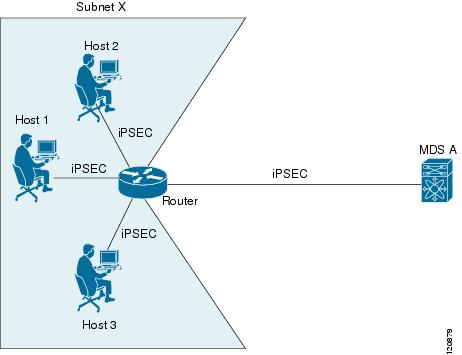
Setting the peer address as AutoPeer in the crypto map indicates that the destination endpoint of the traffic should be used as the peer address for the SA. Using the same crypto map, a unique SA can be set up to each of the endpoints in the subnet specified by the crypto map's ACL entry. Auto-peer simplifies configuration when traffic endpoints are IPsec capable. It is particularly useful for iSCSI, where the iSCSI hosts in the same subnet do not require separate configuration.

Figure 29-6 shows a scenario where the auto-peer option can simplify configuration. Using the auto-peer option, only one crypto map entry is needed for all the hosts from subnet X to set up SAs with the switch. Each host sets up its own SA, but shares the crypto map entry. Without the auto-peer option, each host needs one crypto map entry.

Figure 29-6 iSCSI with End-to-End IPsec Using the Auto-Peer Option

SA Lifetime Negotiation

To specify SA lifetime negotiation values, you can optionally configure the lifetime value for a specified crypto map. If you do, this value overrides the globally set values. If you do not specify the crypto map specific lifetime, the global value (or global default) is used.

Perfect Forwarding Secrecy

To specify SA lifetime negotiation values, you can also optionally configure the perfect forwarding secrecy (PFS) value in the crypto map.

The PFS feature is disabled by default. If you set the PFS group, you can set one of DH groups: 1, 2, 5, or 14. If you do not specify a DH group, the software uses group 1 by default.

Creating or Modifying Crypto Maps

When configuring crypto map entries, follow these guidelines:

The sequence number for each crypto map decides the order in which the policies are applied. A lower sequence number is assigned a higher priority.

Only one ACL is allowed for each crypto map entry (the ACL itself can have multiple entry or deny entries).

When the tunnel endpoint is the same as the destination address, you can used the AutoPeer option to dynamically configure the peer.

To create or modify crypto map entries using Fabric Manager, follow these steps:


Step 1 Choose Switches > Security > IPSEC in the Physical Attributes pane. You see the IPSEC configuration in the Information pane.

Step 2 Choose the CryptoMap Set Entry tab. You see the existing crypto maps configured.

Step 3 Optionally, click Create Row to create a new crypto map entry. You see the Create Crypto Map dialog box.

Step 4 Select the switch you want to configure or modify. If you are creating a new crypto map, set the setName and priority for this crypto map.

Step 5 Set the IP-ACL and TransformSetIdList for this crypto map.

Step 6 Optionally, check the AutoPeer check box or set the Peer address if you are creating a new crypto map. See the "The AutoPeer Option" section.

Step 7 Choose the appropriate PFS radio button. See the "Perfect Forwarding Secrecy" section.

Step 8 Set the Lifetime and LifeSize. See the "SA Lifetime Negotiation" section.

Step 9 Optionally, click Create if you are creating a new crypto map, or click the Apply Changes icon if you are modifying an existing crypto map.


Applying a Crypto Map Set to an Interface

You need to apply a crypto map set to each interface through which IPsec traffic will flow. Applying the crypto map set to an interface instructs the switch to evaluate all the interface's traffic against the crypto map set and to use the specified policy during connection or SA negotiation on behalf of traffic to be protected by crypto.

You can apply only one crypto map set to an interface. You can apply the same crypto map to multiple interfaces. However, you cannot apply more than one crypto map set to each interface.

To apply a crypto map set to an interface using Fabric Manager, follow these steps:


Step 1 Choose Switches > Security > IPSEC in the Physical Attributes pane. You see the IPSEC configuration in the Information pane.

Step 2 Choose the Interfaces tab. You see the existing interface to crypto map configuration.

Step 3 Optionally, click Create Row to create a apply a crypto map to an interface. You see the Interfaces Create dialog box.

Step 4 Select the switch and interface you want to configure.

Step 5 Select the CryptomapSetName to the name of the crypto map you want to apply to this interface.

Step 6 Click Create to apply the crypto map to the selected interface or click Close to exit the dialog box without applying the crypto map.


IPsec Maintenance

Certain configuration changes will only take effect when negotiating subsequent security associations. If you want the new settings to take immediate effect, you must clear the existing security associations so that they will be re-established with the changed configuration. If the switch is actively processing IPsec traffic, it is desirable to clear only the portion of the security association database that would be affected by the configuration changes (that is, clear only the security associations established by a given crypto map set). Clearing the full security association database should be reserved for large-scale changes, or when the router is processing very little other IPsec traffic.

Global Lifetime Values

You can change the global lifetime values which are used when negotiating new IPsec SAs and override configured global lifetime values for a specified crypto map entry.

You can configure two lifetimes: timed or traffic-volume. A SA expires after the first of these lifetimes is reached. The default lifetimes are 3,600 seconds (one hour) and 4,500 MB.

If you change a global lifetime, the new lifetime value will not be applied to currently existing SAs, but will be used in the negotiation of subsequently established SAs. If you wish to use the new values immediately, you can clear all or part of the SA database.

Assuming that the particular crypto map entry does not have lifetime values configured, when the switch requests new SAs it will specify its global lifetime values in the request to the peer; it will use this value as the lifetime of the new SAs. When the switch receives a negotiation request from the peer, it uses the value determined by the IKE version in use:

If you use IKE version 1 (IKEv1) to setup IPsec SAs, the SA lifetime values are chosen to be the smaller of the two proposals. The same values are programmed on both the ends of the tunnel.

If you use IKE version 2 (IKEv2) to setup IPsec SAs, SAs on each end has its own set up of lifetime values and thus the SAs on both sides expire independently.

The SA (and corresponding keys) will expire according to whichever comes sooner, either after the specified amount of time (in seconds) has passed or after the specified amount of traffic (in bytes) has passed.

A new SA is negotiated before the lifetime threshold (when 10% of the configured value still remains) of the existing SA is reached, to ensure that negotiation completes before the existing SA expires.

If no traffic has passed through when the lifetime expires, a new SA is not negotiated. Instead, a new SA will be negotiated only when IPsec sees another packet that should be protected.