-
Cisco MDS 9000 Family Fabric Manager Configuration Guide, Release 2.x
-
New and Changed Information
-
Index
-
Preface
- Part 1 - Fabric Manager Applications
- Part 2 - Cisco MDS SAN-OS Installation and Configuration Files
-
Part 3 - Switch Configuration
-
Cisco Fabric Services
-
VSAN Configuration
-
Dynamic VSAN Configuration
-
Zone Configuration
-
Inter-VSAN Routing Configuration
-
PortChannel Configuration
-
Interface Configuration
-
FCIP Configuration
-
Configuring the SAN Extension Tuner
-
iSCSI configuration
-
FICON Configuration
-
Configuring Intelligent Storage Services
-
Additional Configuration
-
- Part 4 - Security Configuration
- Part 5 - Network and Performance Monitoring
- Part 6 - Troubleshooting
-
GUI/CLI Usage Chart
-
Interface Nonoperational Reason Codes
-
Managing Cisco FabricWare
-
 Feedback
Table Of Contents
Fabric-Optimization with VSANs
VSANs for FICON and FCP Intermixing
Cisco MDS-Supported FICON Features
FICON Port Numbering Guidelines
FCIP and PortChannel Port Numbers
Installed and Uninstalled Ports
Creating FICON VSANs and enabling FICON
Viewing FICON Director History
Host Changes FICON Port Parameters
FICON Information Refresh Note
Configuring Port Blocking and Port Prohibiting
Entering FICON Port Configuration Information
Accessing FICON Configuration Files
Copying FICON Configuration Files
Editing FICON Configuration Files
Managing FICON Configuration Files In Device Manager
Clearing FICON Device Allegiance
Port Security Versus Fabric Binding
Configuring a List of Switch WWNs In a Fabric
Saving Fabric Binding Configurations
Fabric Binding CopyActive to Config
Creating a Fabric Binding Configuration
Deleting a Fabric Binding Configuration
Viewing Fabric Binding Active Database
Viewing Fabric Binding Violations
Clearing Fabric Binding Statistics
Calculating FICON Flow Load Balance
FICON Configuration
Fibre Connection (FICON) interface capabilities enhance the Cisco MDS 9000 Family by supporting both open systems and mainframe storage network environments. Inclusion of Control Unit Port (CUP) support further enhances the MDS offering by allowing in-band management of the switch from FICON processors.
The fabric binding feature helps prevent unauthorized switches from joining the fabric or disrupting current fabric operations. The Registered Link Incident Report (RLIR) application provides a method for a switchport to send a LIR to a registered Nx-port.
Note
FICON features can be implemented in any switch in the Cisco MDS 9000 Family running Cisco MDS SAN-OS Release 1.3(x) or earlier. While no hardware changes are required, you do need the MAINFRAME_PKG license to configure FICON parameters (see "Obtaining and Installing Licenses").
This chapter includes the following sections:
•
•
About FICON
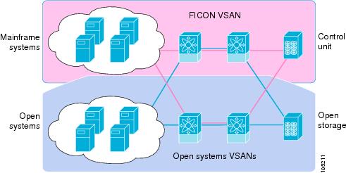
The Cisco MDS 9000 Family supports the Fibre Channel Protocol (FCP), FICON, iSCSI, and FCIP capabilities within a single, high availability platform. This solution simplifies purchasing, reduces deployment and management costs, and reduces the complex evolution to shared mainframe and open systems storage networks (see Figure 22-1).
Figure 22-1 Shared System Storage Network
FCP and FICON are different FC4 protocols and their traffic are independent of each other. If required, devices using these protocols can be isolated using VSANs.
MDS-Specific FICON Advantages
This section explains the additional FICON advantages in Cisco MDS switches.
Fabric-Optimization with VSANs
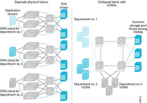
Generally, separate physical fabrics have a high level of switch management and have a higher implementation cost. Further, the ports in each island may be over-provisioned depending on the fabric configuration.
By using the Cisco MDS-specific VSAN technology, you can introduce greater efficiency between these physical fabrics by lowering the cost of over-provisioning and reducing the number of switches to be managed.
VSANs also help you to move unused ports nondisruptively and provide a common redundant physical infrastructure (see Figure 22-2).
Figure 22-2 VSAN-Specific Fabric Optimization
VSANs enable global SAN consolidation by allowing you to convert existing SAN islands into virtual SAN islands on a single physical network. It provides hardware-enforced security and separation between applications or departments to allow coexistence on a single network. It also allows virtual rewiring to consolidate your storage infrastructure. You can move assets between departments or applications without the expense and disruption of physical relocation of equipment.
Note
FCIP Support
The multilayer architecture of the Cisco MDS 9000 Family enables a consistent feature set over a protocol-agnostic switch fabric. Cisco MDS 9500 Series and 9200 Series switches transparently integrate Fibre Channel, FICON, and Fibre Channel over IP (FCIP) in one system. The FICON over FCIP feature enables cost-effective access to remotely located mainframe resources. With the Cisco MDS 9000 Family platform, storage replication services such as IBM PPRC and XRC can be extended over metro to global distances using ubiquitous IP infrastructure and simplifying business continuance strategies.
Caution
PortChannel Support
The Cisco MDS implementation of FICON provides support for efficient utilization and increased availability of inter-switch links necessary to build stable large-scale SAN environments. PortChannels ensure an enhanced ISL availability and performance in Cisco MDS switches.
See "PortChannel Configuration," for more information on PortChannels.
VSANs for FICON and FCP Intermixing
Cisco MDS 9000 Family FICON-enabled switches simplify deployment of even the most complex intermix environments. Multiple logical FICON, Z-Series Linux/FCP, and Open-Systems FCP fabrics can be overlaid onto a single physical fabric by simply creating VSANs as required for each service. VSANs provide both hardware isolation and protocol specific fabric services, eliminating the complexity and potential instability of zone-based intermix schemes.
By default, the FICON feature is disabled in all switches in the Cisco MDS 9000 Family. When the FICON feature is disabled, FC IDs can be allocated seamlessly. Intermixed environments are addressed by the Cisco MDS SAN-OS software. The challenge of mixing Fibre Channel Protocol (FCP) and FICON protocols are addressed by Cisco MDS switches when implementing VSANs.
Switches and directors in the Cisco MDS 9000 Family support FCP and FICON protocol intermixing at the port level. If these protocols are intermixed in the same switch, you can use VSANs to isolate FCP and FICON ports.
Tip
Cisco MDS-Supported FICON Features
The Cisco MDS 9000 Family FICON features include:
•
Refer to the Cisco MDS 9500 Series Hardware Installation Guide and the Cisco MDS 9200 Series Hardware Installation Guide).
•
•
•
•
•
•
•
•
•
•
–
–
–
See the section in this chapter.
•
•
•
•
•
•
•
•
•
•
•
FICON Port Numbering
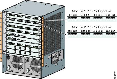
With reference to the FICON feature, ports in Cisco MDS switches are identified by a statically defined 8-bit value known as the port number. Port numbers are assigned based on the module and the slot in the chassis. Port numbers cannot be changed and the first port in a switch always starts with a 0 (see Figure 22-3).
Figure 22-3 Port Number in the Cisco MDS 9000 Family
The FICON port number is assigned based on the front panel location of the port and is specific to the slot in which the module resides. Even if the module is a 16-port module, 32-port numbers are assigned to that module—regardless of the module type (16-port or 32-port), the module's physical presence in the chassis, or the port status (up or down).
Note
Table 22-1 lists the port number assignment for the Cisco MDS 9000 Family of switches and directors.
FICON Port Numbering Guidelines
The following guidelines apply to FICON port numbers:
•
•
•
•
•
FCIP and PortChannel Port Numbers
FCIP and PortChannels cannot be used in a FICON-enabled VSAN unless they are explicitly bound to a port number.
Port Addresses
By default, port numbers are the same as port addresses (see the "Editing FICON Configuration Files" section).
Implemented and Unimplemented Port Addresses
An implemented port refers to any port address that is available in the chassis.
An unimplemented port refers to any port address that is not available in the chassis.
Tip
Installed and Uninstalled Ports
An installed port refers to a port for which all required hardware is present. A specified port number in a VSAN can be implemented, and yet not installed, if any of the following conditions apply:
•
•
•
Another scenario is if VSANs 1 through 5 are FICON-enabled, and trunking-enabled interface fc1/1 has VSANs 3 through 10, then port address 0 is uninstalled in VSAN 1 and 2.
•
FC ID Allocation
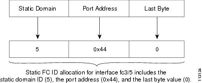
FICON requires a predictable and static FC ID allocation scheme. When FICON is enabled, the FC ID allocated to a device is based on the port address of the port to which it is attached. The port address forms the middle byte of the fabric address. Additionally, the last byte of the fabric address should be the same for all devices in the fabric. By default, the last byte value is 0 and can be configured.
Note
Cisco MDS switches have a dynamic FC ID allocation scheme. When FICON is enabled or disabled on a VSAN, all the ports are flapped to switch from the dynamic to static FC IDs and vice versa (see Figure 22-4).
Figure 22-4 Static FC ID Allocation for FICON
FICON Cascading
The Cisco MDS SAN-OS software allows multiple switches in a FICON network. To configure multiple switches, you must enabled and configure fabric binding in that switch.
FICON VSAN Prerequisites
To ensure that a FICON VSAN is operationally up, be sure to verify the following requirements:
•
•
•
•
•
•
If any of these requirements are not met, the FICON feature cannot be enabled.
Enabling FICON
By default FICON is disabled in all switches in the Cisco MDS 9000 Family. When you enable the FICON feature in Cisco MDS switches, the following apply:
•
•
•
•
Creating FICON VSANs and enabling FICON
When a new FICON VSAN is created, static (insistent) domain IDs, in-order delivery, and fabric binding must be enabled so the FICON VSAN can operate. When you enable the FICON feature in Cisco MDS switches, the following apply:
•
•
To create a FICON VSAN in Fabric Manager, follow these steps:
Step 1
Step 2
Step 3
Step 4
Step 5
Step 6
Note
Step 7
Step 8
Step 9
Step 10
Step 11
Step 12
Step 13
To create a FICON VSAN in Device Manager, follow these steps:
Step 1
Step 2
Step 3
Step 4
Step 5
Step 6
Step 7
Step 8
Deleting FICON VSANs
To delete a FICON VSAN in Fabric Manager, follow these steps:
Step 1
Step 2
Step 3
Note
To delete a FICON VSAN in Device Manager, follow these steps:
Step 1
Step 2
Step 3
Step 4
Note
Viewing FICON Director History
To view FICON director history, follow these steps:
Step 1
Step 2
Step 3
Step 4
The code-page Option
FICON strings are coded in Extended Binary-Coded Decimal Interchange Code (EBCDIC) format. Refer to your mainframe documentation for details on the code page options.
Cisco MDS switches support international-5, france, brazil, germany, italy, japan, spain-latinamerica, uk, and us-canada (default) EBCDIC format options.
Tip
To modify the code-page option using Device Manager, follow these steps:
Step 1
Step 2
Step 3
Step 4
FC ID Last Byte
Caution
FICON requires the last byte of the fabric address to be the same for all allocated FC IDs. By default, this value is set to 0. You can only change the FC ID last byte when the FICON switch is in the offline state.
FICON Host Control
By default, the clock in each VSAN is the same as the switch hardware clock. Each VSAN in a Cisco MDS switch represents a virtual director. The clock and time present in each virtual director can be different.To maintain separate clocks for each VSAN, the Cisco MDS SAN-OS software maintains the difference of the VSAN-specific clock and the hardware-based director clock. When a host (mainframe) sets the time, the Cisco MDS SAN-OS software updates this difference between the clocks. When a host reads the clock, it computes the difference between the VSAN-clock and the current director hardware clock and presents a value to the mainframe.
To allow the host (mainframe) to control the Cisco MDS switch using Device Manager, follow these steps:
Step 1
Step 2
Step 3
Step 4
Step 5
Host Changes FICON Port Parameters
By default, mainframe users are not allowed to configure FICON parameters on Cisco MDS switches—they can only query the switch.
To allow the host (mainframe) to configure FICON parameters on the Cisco MDS switch using Device Manager, follow these steps:
Step 1
Step 2
Step 3
Step 4
Step 5
Note
FICON Information Refresh Note
When viewing FICON information through the Device Manager dialog boxes, you must manually refresh the display by clicking the Refresh button in order to see the latest updates. This is true whether you configure FICON through the CLI or through the Device Manager.
There is no automatic refresh of FICON information. This information would be refreshed so often that it would affect performance.
Configuring FICON Ports
You can perform FICON configurations on a per-port address basis in the Cisco MDS 9000 Family of switches.
Even if a port is uninstalled, the port address-based configuration is accepted by the Cisco MDS switch. This configuration is applied to the port when the port becomes installed.
Port Blocking
If you block a port, the port is retained in the operationally down state. If you unblock a port, a port initialization is attempted. When a port is blocked, data and control traffic are not allowed on that port.
Physical Fibre Channel port blocks will continue to transmit an Off-Line State (OLS) primitive sequence on a blocked port.
Caution
If a port is shut down, unblocking that port does not initialize the port.
Port Prohibiting
To prevent implemented ports from talking to each other, you can configure prohibits between two or more ports. If you prohibit ports, the specified ports are prevented from communicating with each other.
Note
Tip
Prohibit configurations are always symmetrically applied—if you prohibit Port 0 from talking to port 15, port 15 is automatically prohibited from talking to port 0.
Note
Configuring Port Blocking and Port Prohibiting
To configure port blocking or port prohibiting for FICON using Device Manager, follow these steps:
Step 1
Step 2
Step 3
Step 4
Step 5
Entering FICON Port Configuration Information
Note
To display FICON port configuration information, follow these steps:
Step 1
You see the FICON VSAN configuration dialog box.
Step 2
Step 3
Step 4
Step 5
Viewing FICON Port Attributes
Note
To view FICON port attributes, follow these steps:
Step 1
You see the FICON VSAN configuration dialog box.
Step 2
Step 3
Step 4
FICON Configuration Files
You can save up to 16 FICON configuration files on each FICON-enabled VSAN (in persistent storage). The file format is proprietary to IBM. These files can be read and written by IBM hosts using the in-band CUP protocol. Additionally, you can use the Cisco MDS CLI or Fabric Manager applications to operate these FICON configuration files.
Note
When you enable the FICON feature in a VSAN, the switches always use the startup FICON configuration file, called IPL. This file is created with a default configuration as soon as FICON is enabled in a VSAN.
Caution
FICON configuration files contain the following configuration for each implemented port address:
•
•
•
Note
Accessing FICON Configuration Files
Only one user can access the configuration file at any given time:
•
•
•
FICON configuration files can be accessed by any host, SNMP, or CLI user who is permitted to access the switch. The locking mechanism in the Cisco MDS SAN-OS software restricts access to one user at a time per file. This lock applies to newly created files and previously saved files. Before accessing any file, you must lock the file and obtain the file key. A new file key is used by the locking mechanism for each lock request. The key is discarded when the lock timeout of 15 seconds expires. The lock timeout value cannot be changed.
If a specified file does not exist, it is created. Up to 16 files can be saved. Each file name is restricted to eight alphanumeric characters.
Note
Copying FICON Configuration Files
The Cisco MDS SAN-OS software maintains different configuration files to support a FICON network. These configuration files can be are saved using the copy running-config startup-config command, or using Device Manager. FICON configuration files do not contain the following information that is normally saved with the running configuration:
Note
•
•
•
•
FICON configuration files are independent of these parameters. Instead, this information is stored in persistent storage as they can be modified independent of the startup configuration.
Editing FICON Configuration Files
The configuration file submode allows you to create and edit FICON configuration files. If a specified file does not exist, it is created. Up to 16 files can be saved. Each file name is restricted to eight alphanumeric characters.
Managing FICON Configuration Files In Device Manager
To manage a FICON file using Device Manager, follow these steps:
Step 1
Step 2
Step 3
a.
b.
c.
Step 4
Step 5
Step 6
Step 7
Port Swapping
The FICON port swap feature is only provided for maintenance purposes.
The FICON port swapping feature causes all configuration associated with old-port-number and new port-number to be swapped, including VSAN configurations.
Cisco MDS switches allow port swapping for non-existent ports as follows:
•
•
•
Tip
Once you swap ports, the switch automatically performs the following actions:
•
•
•
Port Swapping Guidelines
Be sure to follow these guidelines when using the FICON port swap feature:
•
•
•
•
Note
Swapping FICON Ports
Note
To swap ports using Device Manager, follow these steps:
Step 1
Step 2
Clearing FICON Device Allegiance
FICON requires serialization of access among multiple mainframes, CLI, and SNMP sessions be maintained on Cisco MDS 9000 Family switches by controlling device allegiance for the currently executing session. Any other session is denied permission to perform configuration changes unless the required allegiance is available.
Caution
CUP In-Band Management
The Control Unit Port (CUP) protocol configures access control and provides unified storage management capabilities from a mainframe computer. Cisco MDS 9000 FICON-enabled switches are fully IBM CUP standard compliant for in-band management using the IBM S/A OS/390 I/O operations console.
Note
CUP is supported by switches and directors in the Cisco MDS 9000 Family. The CUP function allows the mainframe to manage the Cisco MDS switches.
Host communication includes control functions such as blocking and unblocking ports, as well as monitoring and error reporting functions.
Fabric Binding Configuration
The Cisco MDS SAN-OS Release 1.3(x) fabric binding feature ensures ISLs are only enabled between specified switches in the fabric binding configuration. Fabric binding is configured on a per-VSAN basis and can only be implemented in FICON VSANs. You can still perform fabric binding configuration in a non-FICON VSAN—these configurations will only come into effect after FICON is enabled.
This feature helps prevent unauthorized switches from joining the fabric or disrupting current fabric operations. It uses the Exchange Fabric Membership Data (EFMD) protocol in FICON networks to ensure that the list of authorized switches is identical in all switches in the fabric.
Port Security Versus Fabric Binding
Port security and fabric binding are two independent features that can be configured to complement each other (see Table 22-2).
Port-level checking for xE-ports
•
•
–
–
While port security complements fabric binding, they are independent features and can be enabled or disabled separately.
Fabric Binding Enforcement
To enforce fabric binding, configure the switch world wide name (sWWN) to specify the xE port connection for each switch. Enforcement of fabric binding policies are done on every activation and when the port tries to come up. However, enforcement of fabric binding at the time of activation happens only if the VSAN is a FICON VSAN. The fabric binding feature requires all sWWNs connected to a switch and their persistent domain IDs to be part of the fabric binding active database.
To configure fabric binding in each switch in the fabric, follow these steps.
Step 1
Step 2
Step 3
Step 4
Step 5
Enabling Fabric Binding
The fabric binding feature must be enabled in each switch in the fabric that participates in the fabric binding. By default, this feature is disabled in all switches in the Cisco MDS 9000 Family. The configuration and verification commands for the fabric binding feature are only available when fabric binding is enabled on a switch. When you disable this configuration, all related configurations are automatically discarded.
To enable fabric binding using Fabric Manager, follow these steps:
Step 1
Step 2
Step 3
Configuring a List of Switch WWNs In a Fabric
A user-specified fabric binding list contains a list of switch WWNs (sWWNs) within a fabric. If a sWWN attempts to join the fabric, and that sWWN is not in the list or the sWWN is using a domain ID that differs from the one specified in the allowed list, the ISL between the switch and the fabric is automatically isolated in that VSAN and the switch is denied entry into the fabric.
The persistent domain ID must be specified along with the sWWN. Domain ID authorization is required in FICON VSANs where the domains are statically configured and the end devices reject a domain ID change in all switches in the fabric.
To configure a list of switches for fabric binding using Fabric Manager, follow these steps:
Step 1
Step 2
Step 3
Activating Fabric Binding
The fabric binding maintains a configuration database (config-database) and an active database. The config-database is a read-write database that collects the configurations you perform. These configurations are only enforced upon activation. This activation overwrites the active database with the contents of the config database. The active database is read-only and is the database that checks each switch that attempts to log in.
By default, the fabric binding feature is not activated. You cannot activate the switch if entries existing in the config database conflict with the current state of the fabric. For example, one of the already logged in switches may be denied login by the config database. You can choose to forcefully override these situations.
Note
The fabric binding feature must be enabled in each switch in the fabric that participates in the fabric binding. By default, this feature is disabled in all switches in the Cisco MDS 9000 Family.
If the database activation is rejected due to one or more conflicts listed in the previous section, you may decide to proceed with the activation by using the forceActivate option.
To activate fabric binding, follow these steps:
Step 1
Step 2
Step 3
Saving Fabric Binding Configurations
When you save the fabric binding configuration, the config database and the active database are both saved to the startup configuration and are available after a reboot.
Caution
Deactivating Fabric Binding
To deactivate fabric binding, follow these steps:
Step 1
Step 2
Step 3
Fabric Binding CopyActive to Config
To copy the active fabric binding to the configuration file, follow these steps:
Step 1
Step 2
Step 3
Creating a Fabric Binding Configuration
To create a fabric binding configuration, follow these steps:
Step 1
Step 2
Step 3
Step 4
Deleting a Fabric Binding Configuration
To delete a fabric binding configuration, follow these steps:
Step 1
Step 2
Step 3
Viewing Fabric Binding Active Database
To view the fabric binding active database, follow these steps:
Step 1
You see the active database.
Viewing Fabric Binding Violations
To view fabric binding violations, follow these steps:
Step 1
You see the violations.
Clearing Fabric Binding Statistics
To clear fabric binding statistics, follow these steps:
Step 1
You see the statistics in the Information pane.
Step 2
Step 3
Viewing EFMD Statistics
To view EFMD statistics, follow these steps:
Step 1
Step 2
Displaying RLIR Information
The Registered Link Incident Report (RLIR) application provides a method for a switchport to send an LIR to a registered Nx-port. It is a highly-available application.
When a Link Incident Record (LIR) is detected in FICON-enabled switches in the Cisco MDS 9000 Family from a RLIR Extended Link Service (ELS). it sends that record to the members in it's Established Registration List (ERL).
In case of multi-switch topology, a Distribute Registered Link Incident Record (DRLIR) Inter Link Service (ILS) is sent to all reachable remote domains along with the RLIR ELS. On receiving the DRLIR ILS, the switch extracts the RLIR ELS and sends to the members of the ERL.
The Nx-ports interested in receiving the RLIR ELS send Link Incident Record Registration (LIRR) ELS request to the management server on the switch. The RLIRs are processed on a per-VSAN basis.
To view RLR information using Device Manager, follow these steps:
Step 1
Step 2
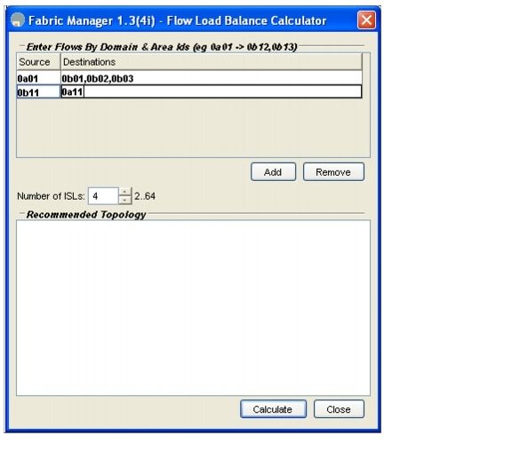
Calculating FICON Flow Load Balance
The FICON Flow Load Balance Calculator allows you to get the best load balancing configuration for your FICON flows. The calculator does not rely on any switch or flow discovery in the fabric. It is available from the Fabric Manager Tools menu.
To use the FICON Flow Load Balance calculator, follow these steps:
Step 1
Step 2
Use 2 byte hex (Domain and Area IDs) as shown in Figure 22-5.You can copy and paste these IDs, and then edit them if you need to. To remove a row, select it and click Remove.
Figure 22-5 Flow Load Balance Calculator - Initial Screen
Step 3
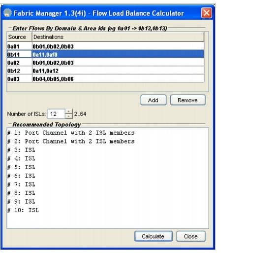
Step 4
In the example shown in Figure 22-6, there are 12 ISLs between domains 0a and 0b with 13 flows. In this case, the best balance is 2 Port Channels with 2 members each, and 8 regular ISLs.
Figure 22-6 Flow Load Balance Calculator - Example
Note