-
Catalyst 4500 Series Software Configuration Guide, 7.5
-
Preface
-
Product Overview
-
Using the Command-Line Interface
-
Configuring the Switch IP Address and Default Gateway
-
Configuring Ethernet and Fast Ethernet Switching
-
Configuring Gigabit Ethernet Switching
-
Configuring Fast EtherChannel and Gigabit EtherChannel
-
Configuring Spanning Tree
-
Configuring Spanning Tree PortFast, BPDU Guard, BPDU Filter, UplinkFast, BackboneFast, and Loop Guard
-
Configuring VTP
-
Configuring VLANs
-
Configuring VLAN Trunks on Fast Ethernet and Gigabit Ethernet Ports
-
Configuring Dynamic VLAN Membership with VMPS
-
Configuring GVRP
-
Configuring QoS
-
Configuring Multicast Services
-
Configuring Port Security
-
Configuring Unicast Flood Blocking
-
Configuring the IP Permit List
-
Configuring Protocol Filtering
-
Checking Port Status and Connectivity
-
Configuring CDP
-
Using Switch TopN Reports
-
Configuring UDLD
-
Configuring SNMP
-
Configuring RMON
-
Configuring SPAN and RSPAN
-
Administering the Switch
-
Configuring Switch Access Using AAA
-
Modifying the Switch Boot Configuration
-
Working with System Software Images
-
Using the Flash File System
-
Working with Configuration Files
-
Configuring Switch Acceleration
-
Configuring System Message Logging
-
Configuring DNS
-
Configuring NTP
-
Glossary
-
Index
-
 Feedback
Table Of Contents
Creating or Modifying an Ethernet VLAN
Creating or Modifying a Normal-Range Ethernet VLAN
Creating or Modifying an Extended-Range VLAN
Assigning Switch Ports to a VLAN
Mapping 802.1Q VLANs to ISL VLANs
Clearing 802.1Q-to-ISL VLAN Mappings
Private VLAN Configuration Guidelines
Viewing the Port Capability of a Private VLAN Port
Deleting an Isolated or Community VLAN
Deleting a Private VLAN Mapping
Configuring VLANs
This chapter describes how to configure virtual LANs (VLANs) on the Catalyst enterprise LAN switches.
Note
For complete syntax and usage information for the commands used in this chapter, refer to the Command Reference—Catalyst 4000 Family, Catalyst 2948G, and Catalyst 2980G Switches.
This chapter contains these major sections:
•
Understanding How VLANs Work
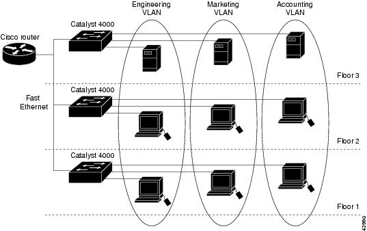
A VLAN is a group of end stations with a common set of requirements, independent of physical location. A VLANs has the same attributes as a physical LAN but allows you to group end stations even if they are not located physically on the same LAN segment.
VLANs allow you to group ports on a switch to limit unicast, multicast, and broadcast traffic flooding. Flooded traffic originating from a particular VLAN is only flooded out other ports belonging to that VLAN.
Note
Figure 10-1 shows an example of VLANs segmented into logically defined networks.
Figure 10-1 VLANs as Logically Defined Networks
VLANs are often associated with IP subnetworks. For example, all the end stations in a particular IP subnet belong to the same VLAN. Traffic between VLANs must be routed. Port VLAN membership on the switch is assigned manually on a port-by-port basis. When you assign switch ports to VLANs using this method, it is known as port-based, or static, VLAN membership.
The in-band (sc0) interface of a switch can be assigned to any VLAN, so you can access another switch on the same VLAN directly without a router. Only one IP address at a time can be assigned to the in-band interface. If you change the IP address and assign the interface to a different VLAN, the previous IP address and VLAN assignment are overwritten.
You can set the following parameters when you create a VLAN in the management domain:
•
•
•
•
•
•
•
Note
VLAN Ranges
Catalyst 4000 family switches support 4096 VLANs in accordance with the IEEE 802.1Q standard. These VLANs are organized into several ranges; you use each range slightly differently. Some of these VLANs are propagated to other switches in the network when you use a management protocol, such as the VLAN Trunking Protocol (VTP). Other VLANs are not propagated, and you must configure them on each applicable switch.
There are three ranges of VLANs:
•
•
•
Table 10-1 describes the VLAN ranges.
Configurable VLAN Parameters
When you create VLANs 2-1000 or modify VLANs 2-1005, you can set the parameters as follows:
•
•
•
•
•
•
•
•
•
•
Note
VLAN Default Configuration
Table 10-2 shows the default VLAN configuration.
VLAN Configuration Guidelines
This section describes the configuration guidelines for creating and modifying VLANs in your network:
•
•
•
•
•
•
Consider the following when creating or modifying extended-range VLANs:
•
•
•
•
•
Note
Configuring VLANs
VLANs are either normal range or extended range. VLANs in the normal range are VLANs 2-1000. VLANs in the extended range are VLANs 1025-4094.
When you configure normal-range VLANs, VLANs 2-1000, you can configure one VLAN at a time or a range of VLANs, all with a single command. If you configure a range of VLANs, you cannot specify a name, because VLAN names must be unique.
Note
You can use VTP to manage global normal-range VLAN configuration information on your network; but not extended-range VLAN configuration information. In order to use VTP, you must configure it before you create any normal-range VLANs. For more information about configuring VTP, see "Configuring VTP."
Before configuring extended-range VLANs, VLANs 1025-4094, you must first enable MAC address reduction. When you enable MAC address reduction the system commits the IDs for extended-range VLANs. After you enable MAC address reduction, you cannot disable it as long as any extended-range VLANs exist.
Note
Creating or Modifying an Ethernet VLAN
To create a new Ethernet VLAN, perform this task in privileged mode:
Step 1
Create a new Ethernet VLAN.
set vlan vlan_num [name name] [said said] [mtu mtu] [translation vlan_num]
Step 2
Verify the VLAN configuration.
show vlan [vlan_num]
Note
This example shows how to create an Ethernet VLAN and verify the configuration:
Console> (enable) set vlan 500 name EngineeringVlan 500 configuration successfulConsole> (enable) show vlan 500VLAN Name Status IfIndex Mod/Ports, Vlans---- -------------------------------- --------- ------- ------------------------500 Engineering active 344VLAN Type SAID MTU Parent RingNo BrdgNo Stp BrdgMode Trans1 Trans2---- ----- ---------- ----- ------ ------ ------ ---- -------- ------ ------500 enet 100500 1500 - - - - - 0 0VLAN AREHops STEHops Backup CRF---- ------- ------- ----------Console> (enable)To modify the VLAN parameters on an existing Ethernet VLAN, perform this task in privileged mode:
This example shows how to change the vlan 500 name from Engineering to Development and verify the configuration:
Console> (enable) set vlan 500 name DevelopmentVlan 500 configuration successfulConsole> (enable) show vlan 500VLAN Name Status IfIndex Mod/Ports, Vlans---- -------------------------------- --------- ------- ------------------------500 Development active 344VLAN Type SAID MTU Parent RingNo BrdgNo Stp BrdgMode Trans1 Trans2---- ----- ---------- ----- ------ ------ ------ ---- -------- ------ ------500 enet 100500 1500 - - - - - 0 0VLAN AREHops STEHops Backup CRF---- ------- ------- ----------Console> (enable)Creating or Modifying a Normal-Range Ethernet VLAN
To create a normal-range Ethernet VLAN, perform this task in privileged mode:
Step 1
Create a normal-range Ethernet VLAN.
set vlan vlan [name name] [said said] [mtu mtu] [translation vlan]
Step 2
Verify the VLAN configuration.
show vlan [vlan]
This example shows how to create normal-range VLANs when the switch is in per-VLAN spanning tree + (PVST+) mode:
Console> (enable) set vlan 500-520Vlan 500 configuration successfulVlan 501 configuration successfulVlan 502 configuration successfulVlan 503 configuration successful..Vlan 520 configuration successfulConsole> (enable)This example shows how to verify that the switch is in PVST+ mode:
Console> (enable) show vlan 500-520VLAN Name Status IfIndex Mod/Ports, Vlans---- -------------------------------- --------- ------- ------------------------500 active 342501 active 343502 active 344503 active 345...520 active 362VLAN Type SAID MTU Parent RingNo BrdgNo Stp BrdgMode Trans1 Trans2---- ----- ---------- ----- ------ ------ ------ ---- -------- ------ ------500 enet 100500 1500 - - - - - 0 0501 enet 100501 1500 - - - - - 0 0502 enet 100502 1500 - - - - - 0 0503 enet 100503 1500 - - - - - 0 0...520 enet 100520 1500 - - - - - 0 0VLAN AREHops STEHops Backup CRF---- ------- ------- ----------Console> (enable)To modify VLAN parameters on an existing normal-range VLAN, perform this task in privileged mode:
This example shows how to change the state of an Ethernet VLAN and verify the configuration:
Console> (enable) set vlan 500 state suspendVlan 500 configuration successfulConsole> (enable) show vlan 500VLAN Name Status IfIndex Mod/Ports, Vlans---- -------------------------------- --------- ------- ------------------------500 Engineering suspend 344VLAN Type SAID MTU Parent RingNo BrdgNo Stp BrdgMode Trans1 Trans2---- ----- ---------- ----- ------ ------ ------ ---- -------- ------ ------500 enet 100500 1500 - - - - - 0 0VLAN AREHops STEHops Backup CRF---- ------- ------- ----------Console> (enable)Creating or Modifying an Extended-Range VLAN
To create an extended-range Ethernet VLAN, perform this task in privileged mode:
Step 1
Enable MAC address reduction.
set spantree macreduction {enable | disable}
Step 2
Create a VLAN.
set vlan vlan
Step 3
Verify the VLAN configuration.
show vlan [vlan]
This example shows how to enable MAC address reduction and create an extended-range Ethernet VLAN:
Console> (enable) set spantree macreduction enableMAC address reduction enabledConsole> (enable) set vlan 2000Vlan 2000 configuration successfulConsole> (enable) show vlan 2000VLAN Name Status IfIndex Mod/Ports, Vlans---- -------------------------------- --------- ------- ------------------------2000 VLAN2000 active 61VLAN Type SAID MTU Parent RingNo BrdgNo Stp BrdgMode Trans1 Trans2---- ----- ---------- ----- ------ ------ ------ ---- -------- ------ ------2000 enet 102000 1500 - - - - - 0 0VLAN Inst DynCreated RSPAN---- ---- ---------- --------2000 - static disabledVLAN AREHops STEHops Backup CRF 1q VLAN---- ------- ------- ---------- -------Console> (enable)To modify the VLAN parameters on an existing extended-range VLAN, perform this task in privileged mode:
This example shows how to change the state of an extended-range Ethernet VLAN and verify the configuration:
Console> (enable) set vlan 2000 state suspendVlan 2000 configuration successfulConsole> (enable) show vlan 2000VLAN Name Status IfIndex Mod/Ports, Vlans---- -------------------------------- --------- ------- ------------------------2000 VLAN2000 suspend 61VLAN Type SAID MTU Parent RingNo BrdgNo Stp BrdgMode Trans1 Trans2---- ----- ---------- ----- ------ ------ ------ ---- -------- ------ ------2000 enet 102000 1500 - - - - - 0 0VLAN Inst DynCreated RSPAN---- ---- ---------- --------2000 - static disabledVLAN AREHops STEHops Backup CRF 1q VLAN---- ------- ------- ---------- -------Console> (enable)Assigning Switch Ports to a VLAN
A VLAN created in a management domain remains unused until you assign one or more switch ports to the VLAN. If you specify a VLAN that does not exist, the VLAN is created and the specified ports are assigned to it.
To assign one or more switch ports to a VLAN, perform this task in privileged mode:
Step 1
Assign one or more switch ports to a VLAN.
set vlan vlan_num mod_num/port_num
Step 2
Verify the port VLAN membership.
show vlan [vlan_num]
show port [mod_num[/port_num]]
This example shows how to assign switch ports to a VLAN and verify the assignment:
Console> (enable) set vlan 500 2/4VLAN 500 modified.VLAN 560 modified.VLAN Mod/Ports---- -----------------------500 2/4Console> (enable) show vlan 500VLAN Name Status IfIndex Mod/Ports, Vlans---- -------------------------------- --------- ------- ------------------------500 Engineering active 59 2/4VLAN Type SAID MTU Parent RingNo BrdgNo Stp BrdgMode Trans1 Trans2---- ----- ---------- ----- ------ ------ ------ ---- -------- ------ ------500 enet 100500 1500 - - - - - 0 0VLAN AREHops STEHops Backup CRF---- ------- ------- ----------Console> (enable) show port 2/4Port Name Status Vlan Level Duplex Speed Type----- ------------------ ---------- ---------- ------ ------ ----- ------------2/4 notconnect 500 normal auto auto 10/100BaseTXPort Security Secure-Src-Addr Last-Src-Addr Shutdown Trap IfIndex----- -------- ----------------- ----------------- -------- -------- -------2/4 disabled No disabled 12Port Status Channel Channel Neighbor Neighbormode status device port----- ---------- --------- ----------- ------------------------- ----------2/4 notconnect auto not channelPort Align-Err FCS-Err Xmit-Err Rcv-Err UnderSize----- ---------- ---------- ---------- ---------- ---------2/4 - 0 0 0 0Port Single-Col Multi-Coll Late-Coll Excess-Col Carri-Sen Runts Giants----- ---------- ---------- ---------- ---------- --------- --------- ---------2/4 0 0 0 0 0 0 0Last-Time-Cleared--------------------------Wed Jul 26 2000, 19:44:05Console> (enable)Mapping 802.1Q VLANs to ISL VLANs
The valid range of user-configurable ISL VLANs is 1-1000. The valid range of VLANs specified in the IEEE 802.1Q standard is 0-4095. In a network environment with non-Cisco devices connected to Cisco switches through 802.1Q trunks, you must map 802.1Q VLAN numbers greater than 1000 to ISL VLAN numbers.
802.1Q VLANs in the range 1-1000 are automatically mapped to the corresponding ISL VLAN. 802.1Q VLAN numbers greater than 1000 must be mapped to an ISL VLAN in order to be recognized and forwarded by Cisco switches.
These restrictions apply when mapping 802.1Q VLANs to ISL VLANs:
•
•
•
•
•
•
To map an 802.1Q VLAN to an ISL VLAN, perform this task in privileged mode:
This example shows how to map 802.1Q VLANs 2000, 3000, and 4000 to ISL VLANs 200, 300, and 400 and how to verify the configuration:
Console> (enable) set vlan mapping dot1q 2000 isl 200802.1q vlan 2000 is existent in the mapping tableConsole> (enable) set vlan mapping dot1q 3000 isl 300Vlan mapping successfulConsole> (enable) set vlan mapping dot1q 4000 isl 400Vlan mapping successfulConsole> (enable) show vlan mapping802.1q vlan ISL vlan Effective------------------------------------------2000 200 true3000 300 true4000 400 trueConsole> (enable)Clearing 802.1Q-to-ISL VLAN Mappings
To clear an 802.1Q-to-ISL VLAN mapping, perform this task in privileged mode:
Step 1
Clear an 802.1Q-to-ISL VLAN mapping.
clear vlan mapping dot1q {dot1q_vlan | all}
Step 2
Verify the VLAN mapping.
show vlan mapping
This example shows how to clear the VLAN mapping for 802.1Q VLAN 2000:
Console> (enable) clear vlan mapping dot1q 2000Vlan 2000 mapping entry deletedConsole> (enable)This example shows how to clear all 802.1Q-to-ISL VLAN mappings:
Console> (enable) clear vlan mapping dot1q allAll vlan mapping entries deletedConsole> (enable)Deleting a VLAN
When you delete a VLAN in VTP server mode, the VLAN is removed from all switches in the VTP domain. When you delete a VLAN in VTP transparent mode, the VLAN is deleted only on the current switch. When you are on a VTP client, you can only delete a VLAN on the local switch.
Caution
To delete a VLAN on the switch, perform this task in privileged mode:
This example shows how to delete a VLAN (in this case, the switch is a VTP server):
Console> (enable) clear vlan 500This command will deactivate all ports on vlan 500in the entire management domainDo you want to continue (y/n) [n]?yVlan 500 deletedConsole> (enable)Configuring Private VLANs
A private VLAN is a VLAN you configure to have some Layer 2 isolation from other ports within the same private VLAN. Ports belonging to a private VLAN are associated with a common set of supporting VLANs that are used to create the private VLAN structure. You can configure private VLANs and normal VLANs from the same Catalyst 4000 family switch.
There are three types of private VLAN ports: promiscuous, isolated, and community.
•
•
•
Privacy is granted at the Layer 2 level because the switch blocks outgoing traffic to all isolated ports. You assign all isolated ports to an isolated VLAN where this hardware function occurs. Traffic received from an isolated port is forwarded to all promiscuous ports only.
Within a private VLAN are three distinct classifications of VLANs: a single primary VLAN, a single isolated VLAN, and a series of community VLANs.
Define each supporting VLAN within a private VLAN structure before configuring the private VLAN:
•
•
•
To create a private VLAN, you assign two or more normal VLANs in the normal VLAN range: one VLAN is designated as a primary VLAN, a second VLAN is designated as either an isolated VLAN, community VLAN, or two-way community VLAN. You can designate additional VLANs as separate isolated, community, or two-way community VLANs in this private VLAN. After designating the VLANs, you must bind them together and associate them to the promiscuous port.
You can extend private VLANs across multiple Ethernet switches by trunking the primary, isolated, and any community VLANs to other switches that support private VLANs.
In an Ethernet-switched environment, you can assign an individual VLAN and associated IP subnet to each individual or common group of stations. The servers only require the ability to communicate only with a default gateway to gain access to end points outside the VLAN itself. By incorporating these stations, regardless of ownership, into one private VLAN, you can do the following:
•
•
•
•
Private VLAN Configuration Guidelines
This section describes the configuration guidelines and restrictions for configuring private VLANs:
•
•
•
–
–
–
–
•
•
•
•
•
•
•
•
–
–
•
•
•
–
–
•
•
•
•
•
•
•
•
•
•
Creating a Private VLAN
You can bind isolated or community VLAN(s) to the primary VLAN without associating the isolated or community ports to the private VLAN by using the set pvlan primary_vlan_num {isolated_vlan_num | community_vlan_num} command.
You can change the isolated or community ports associated to the private VLAN without changing the isolated or community VLANs binding by using the set pvlan primary_vlan_num {isolated_vlan_num | community_vlan_num} mod/port command.
Ports do not have to be on the same switch as long as the switches are connected to the trunk and the private VLAN has not been removed from the trunk.
You must enter the set pvlan command everywhere that a private VLAN needs to be created. This includes entering the command on switches with isolated or community ports, switches with promiscuous ports, and all intermediate switches that need to carry private VLANs on their trunks. On the edge switches that do not have any isolated, community, or promiscuous ports (typically, access switches with no private ports), the private VLANs do not need to be created and can be pruned from the trunks for security reasons.
To create a private VLAN, perform this task in privileged mode:
This example shows how to create a private VLAN using VLAN 7 as the primary VLAN, VLAN 901 as the isolated VLAN, and VLANs 902 and 903 as the community VLANs. VLAN 901 uses module 4, port 3. VLAN 902 uses module 4, ports 4 through 6. VLAN 903 uses module 4, ports 7 through 9. The router is attached to the promiscuous port 3/1.
Before starting, verify that VLANs 7, 901, 902, and 903 have no ports assigned to them; do so by using the show vlan vlan_num command. If any ports are assigned to one or more of these VLANs, set them to some other VLAN using the set vlan vlan_num {mod/port} command.
This example shows how to specify VLAN 7 as the primary VLAN:
Console> (enable) set vlan 7 pvlan-type primaryVlan 7 configuration successfulConsole> (enable)This example shows how to specify VLAN 901 as the isolated VLAN and VLANs 902 and 903 as community VLANs:
Console> (enable) set vlan 901 pvlan-type isolatedVlan 901 configuration successfulConsole> (enable) set vlan 902 pvlan-type communityVlan 902 configuration successfulConsole> (enable) set vlan 903 pvlan-type communityVlan 903 configuration successfulConsole> (enable)This example shows how to bind VLAN 901 to primary VLAN 7 and assign port 4/3 as the isolated port:
Console> (enable) set pvlan 7 901 4/3Successfully set the following ports to Private Vlan 7,901: 4/3Console> (enable)This example shows how to bind VLAN 902 to primary VLAN 7 and assign ports 4/4 through 4/6 as the community port:
Console> (enable) set pvlan 7 902 4/4-6Successfully set the following ports to Private Vlan 7,902:4/4-6Console> (enable)This example shows how to bind VLAN 903 to primary VLAN 7 and assign port 4/7 through 4/9 as the community ports:
Console> (enable) set pvlan 7 903Successfully set association between 7 and 903.Console> (enable) set pvlan 7 903 4/7-9Successfully set the following ports to Private Vlan 7,903:4/7-9Console> (enable)This example shows how to map the isolated/community VLAN to the primary VLAN on the promiscuous port, 3/1, for each isolated or community VLAN:
Console> (enable) set pvlan mapping 7 901 3/1Successfully set mapping between 7 and 901 on 3/1Console> (enable) set pvlan mapping 7 902 3/1Successfully set mapping between 7 and 902 on 3/1Console> (enable) set pvlan mapping 7 903 3/1Successfully set mapping between 7 and 903 on 3/1This example shows how to verify the private VLAN configuration:
Console> (enable) show vlan 7VLAN Name Status IfIndex Mod/Ports, Vlans---- -------------------------------- --------- ------- ------------------------7 VLAN0007 active 35 4/4-6VLAN Type SAID MTU Parent RingNo BrdgNo Stp BrdgMode Trans1 Trans2---- ----- ---------- ----- ------ ------ ------ ---- -------- ------ ------7 enet 100010 1500 - - - - - 0 0VLAN DynCreated RSPAN---- ---------- --------7 static disabledVLAN AREHops STEHops Backup CRF 1q VLAN---- ------- ------- ---------- -------Primary Secondary Secondary-Type Ports------- --------- ----------------- -----------------7 901 Isolated 4/37 902 Community 4/4-67 903 Community 4/7-9Console> (enable) show vlan 902VLAN Name Status IfIndex Mod/Ports, Vlans---- -------------------------------- --------- ------- ------------------------902 VLAN0007 active 38 4/4-6VLAN Type SAID MTU Parent RingNo BrdgNo Stp BrdgMode Trans1 Trans2---- ----- ---------- ----- ------ ------ ------ ---- -------- ------ ------7 enet 100010 1500 - - - - - 0 0VLAN DynCreated RSPAN---- ---------- --------7 static disabledVLAN AREHops STEHops Backup CRF 1q VLAN---- ------- ------- ---------- -------Primary Secondary Secondary-Type Ports------- --------- ----------------- -----------------7 902 Isolated 4/4-6Console> (enable) show pvlanPrimary Secondary Secondary-Type Ports------- --------- -------------- ------------7 901 isolated 4/37 902 community 4/4-67 903 community 4/7-9Console> (enable) show pvlan mappingPort Primary Secondary----- -------- ----------3/1 7 901-903Console> (enable) show portPort Name Status Vlan Duplex Speed Type----- ------------------ ---------- ---------- ------ ----- ------------...truncated output...4/3 notconnect 7,901 half 100 100BaseFX MM4/4 notconnect 7,902 half 100 100BaseFX MM4/5 notconnect 7,902 half 100 100BaseFX MM4/6 notconnect 7,902 half 100 100BaseFX MM4/7 notconnect 7,903 half 100 100BaseFX MM4/8 notconnect 7,903 half 100 100BaseFX MM4/9 notconnect 7,903 half 100 100BaseFX MM... truncated output...Viewing the Port Capability of a Private VLAN Port
You can view the port capability of a port in a private VLAN using the show pvlan capability command.
These examples show the port capability for several ports in the following configuration:
Console> (enable) set pvlan 10 20Console> (enable) set pvlan mapping 10 20 3/1Console> (enable) set pvlan mapping 10 20 5/2Console> (enable) set trunk 5/1 desirable isl 1-1005,1025-4094Console> (enable) show pvlan capability 5/20Port 5/20 can be made a private vlan port.Console> (enable) show pvlanPrimary Secondary Secondary-Type Ports------- --------- -------------- ------------10 20 isolatedConsole> (enable) show pvlan capability 3/1Port 3/1 cannot be made a private vlan port due to:------------------------------------------------------Promiscuous ports cannot be made private vlan ports.Deleting a Private VLAN
You can delete a private VLAN by deleting the primary VLAN. If you delete a primary VLAN, all bindings to the primary VLAN are broken, all ports in the private VLAN become inactive, and any related mappings on the promiscuous port(s) are deleted.
To delete a private VLAN, perform this task in privileged mode:
This example shows how to delete primary VLAN 7:
Console> (enable) clear vlan 7This command will de-activate all ports on vlan 7Do you want to continue (y/n) [n]?yVlan 7 deletedConsole> (enable)Deleting an Isolated or Community VLAN
If you delete an isolated or community VLAN, the binding with the primary VLAN is broken, any isolated or community ports associated to the VLAN become inactive, and any related mappings on the promiscuous port(s) are deleted.
To delete a VLAN on the switch, perform this task in privileged mode:
Delete an isolated or community VLAN.
clear vlan {isolated_vlan_num | community_vlan_num}
This example shows how to delete the community VLAN 902:
Console> (enable) clear vlan 902This command will de-activate all ports on vlan 902Do you want to continue (y/n) [n]?yVlan 902 deletedConsole> (enable)Deleting a Private VLAN Mapping
If you delete the private VLAN mapping, the connectivity breaks between the isolated or community ports and the promiscuous port. If you delete all the mappings on a promiscuous port, the promiscuous port becomes inactive. When a private VLAN port is set to inactive, it displays "pvlan-" as its VLAN number in the show port output.
You might set a private VLAN port to inactive for the following reasons:
•
•
To delete a port mapping from a private VLAN, perform this task in privileged mode:
Delete the port mapping from the private VLAN.
clear pvlan mapping primary_vlan {isolated | community} {mod/ports}
This example shows how to delete the mapping of VLAN 902 to 901, previously set on ports 3/2 through 3/5:
Console> (enable) clear pvlan mapping 901 902 3/2-5Successfully cleared mapping between 901 and 902 on 3/2-5 Console> (enable)