-
Catalyst 4500 Series Software Configuration Guide, 7.5
-
Preface
-
Product Overview
-
Using the Command-Line Interface
-
Configuring the Switch IP Address and Default Gateway
-
Configuring Ethernet and Fast Ethernet Switching
-
Configuring Gigabit Ethernet Switching
-
Configuring Fast EtherChannel and Gigabit EtherChannel
-
Configuring Spanning Tree
-
Configuring Spanning Tree PortFast, BPDU Guard, BPDU Filter, UplinkFast, BackboneFast, and Loop Guard
-
Configuring VTP
-
Configuring VLANs
-
Configuring VLAN Trunks on Fast Ethernet and Gigabit Ethernet Ports
-
Configuring Dynamic VLAN Membership with VMPS
-
Configuring GVRP
-
Configuring QoS
-
Configuring Multicast Services
-
Configuring Port Security
-
Configuring Unicast Flood Blocking
-
Configuring the IP Permit List
-
Configuring Protocol Filtering
-
Checking Port Status and Connectivity
-
Configuring CDP
-
Using Switch TopN Reports
-
Configuring UDLD
-
Configuring SNMP
-
Configuring RMON
-
Configuring SPAN and RSPAN
-
Administering the Switch
-
Configuring Switch Access Using AAA
-
Modifying the Switch Boot Configuration
-
Working with System Software Images
-
Using the Flash File System
-
Working with Configuration Files
-
Configuring Switch Acceleration
-
Configuring System Message Logging
-
Configuring DNS
-
Configuring NTP
-
Glossary
-
Index
-
 Feedback
Table Of Contents
UDLD Software and Hardware Requirements
Enabling UDLD on Individual Ports
Disabling UDLD on Individual Ports
Specifying the UDLD Message Interval
Displaying the UDLD Configuration
Configuring UDLD
This chapter describes how to configure the UniDirectional Link Detection (UDLD) protocol on the Catalyst enterprise LAN switches.
Note
For complete syntax and usage information for the commands used in this chapter, refer to the Command Reference—Catalyst 4000 Family, Catalyst 2948G, and Catalyst 2980G Switches.
This chapter consists of these major sections:
•
Understanding How UDLD Works
The UDLD protocol allows devices connected through fiber-optic or copper Ethernet cables (for example, Category 5 cabling) to monitor the physical configuration of the cables and detect when a unidirectional link exists. When a unidirectional link is detected, UDLD shuts down the affected port and alerts the user. Unidirectional links can cause a variety of problems, including spanning-tree topology loops.
UDLD is a Layer 2 protocol that works with Layer 1 mechanisms such as autonegotiation to determine the physical status of a link. At Layer 1, autonegotiation handles physical signaling and fault detection. UDLD also performs tasks that autonegotiation cannot perform such as detecting the identities of neighbors and shutting down misconnected ports. When both autonegotiation and UDLD are enabled, Layer 1 and Layer 2 detection features can work together to prevent physical and logical unidirectional connections and malfunctioning of other protocols.
A unidirectional link occurs whenever traffic transmitted by the local device over a link is received by the neighbor but traffic transmitted from the neighbor is not received by the local device. For example, if one of the fiber strands in a pair is disconnected, as long as autonegotiation is active the link does not stay up. In this situation, the logical link is undetermined, and UDLD does not take any actions. If both fibers are working normally at Layer 1, then UDLD at Layer 2 determines whether those fibers are connected correctly and whether traffic is flowing bidirectionally between the correct neighbors. This check cannot be performed by autonegotiation, because autonegotiation is a Layer 1 feature.
The switch periodically transmits UDLD messages (packets) to neighbor devices on ports with UDLD enabled. If the messages are echoed back to the sender within a specific time frame and they are lacking a specific acknowledgment (echo), the link is flagged as unidirectional and the port is shut down. Devices on both ends of the link must support UDLD in order for the protocol to successfully identify and disable unidirectional links.
Note
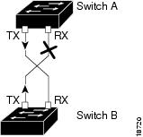
Figure 23-1 shows an example of a unidirectional link condition. Switch B successfully receives traffic from Switch A on the port. However, Switch A does not receive traffic from Switch B on the same port. UDLD detects the problem and disables the port.
Figure 23-1 Unidirectional Link
UDLD Software and Hardware Requirements
UDLD requires the following hardware and software:
•
–
–
•
–
–
Default UDLD Configuration
Table 23-1 shows the default UDLD configuration.
Configuring UDLD
These sections describe how to configure UDLD:
•
•
•
•
•
Enabling UDLD Globally
You must enable UDLD globally before any port can use UDLD.
To enable UDLD globally on the switch, perform this task in privileged mode:
Step 1
Enable UDLD globally on the switch.
set udld enable
Step 2
Verify the configuration.
show udld
This example shows how to enable UDLD globally and verify the configuration:
Console> (enable) set udld enableUDLD enabled globallyConsole> (enable) show udldUDLD : enabledConsole> (enable)Enabling UDLD on Individual Ports
To enable UDLD on individual ports, perform this task in privileged mode:
Step 1
Enable UDLD on a specific port.
set udld enable mod_num/port_num
Step 2
Verify the configuration.
show udld port [mod_num[/port_num]]
This example shows how to enable UDLD on port 4/1 and verify the configuration:
Console> (enable) set udld enable 4/1UDLD enabled on port 4/1Console> (enable) show udld port 4/1UDLD : enabledMessage Interval: 15 secondsPort Admin Status Aggressive Mode Link State-------- ------------ --------------- ---------4/1 enabled disabled bidirectionalConsole> (enable)Disabling UDLD on Individual Ports
To disable UDLD on individual ports, perform this task in privileged mode:
Step 1
Disable UDLD on a specific port.
set udld disable mod_num/port_num
Step 2
Verify the configuration.
show udld port [mod_num[/port_num]]
This example shows how to disable UDLD on port 4/1:
Console> (enable) set udld disable 4/1UDLD disabled on port 4/1.Console> (enable)Disabling UDLD Globally
To disable UDLD globally on the switch, perform this task in privileged mode:
Step 1
Disable UDLD globally on the switch.
set udld disable
Step 2
Verify the configuration.
show udld
This example shows how to disable UDLD globally on the switch:
Console> (enable) set udld disableUDLD disabled globallyConsole> (enable)Specifying the UDLD Message Interval
To specify the UDLD message interval, perform this task in privileged mode:
Step 1
Specify the UDLD message interval.
set udld interval interval
Step 2
Verify the configuration.
show udld
This example shows how to specify the UDLD message interval on the switch:
Console> (enable) set udld interval 10UDLD message interval set to 10 secondsConsole> (enable)This example shows how to verify the message interval on the switch:
Console> (enable) show udldUDLD : enabledMessage Interval : 10 secondsConsole> (enable)Enabling UDLD Aggressive Mode
Software release 5.4(3) and later releases support UDLD aggressive mode. UDLD aggressive mode is disabled by default and its use is recommended only for point-to-point links between Cisco switches running software release 5.4(3) or later releases. With aggressive mode enabled, when a port on a bidirectional link stops receiving UDLD packets, UDLD tries to reestablish the connection with the neighbor. After eight failed retries, the port is put into errdisable state.
In order to prevent spanning tree loops, normal UDLD with the message interval of 15 seconds is fast enough to shut down a unidirectional link before a blocking port transitions to forwarding state (when default spanning tree parameters are used).
Enabling UDLD aggressive mode provides additional benefits in the following cases:
•
•
In these cases, UDLD aggressive mode error disables one of the ports on the link and stops the loss of traffic. Even with aggressive mode disabled, there is no risk for a broadcast storm due to a spanning tree loop in this situation, because one port cannot pass traffic in both directions.
To enable UDLD aggressive mode on module ports, perform this task in privileged mode:
Step 1
Enable UDLD aggressive mode.
set udld aggressive-mode enable mod_num/port_num
Step 2
Verify the configuration.
show udld
This example shows how to enable UDLD aggressive mode on the switch:
Console> (enable) set udld aggressive-mode enable 4/1Aggressive UDLD enabled on port 4/1.Console> (enable)This example shows how to verify that UDLD aggressive mode is enabled on the switch:
Console> (enable) show udld port 4/1UDLD : enabledMessage Interval: 10 secondsPort Admin Status Aggressive Mode Link State-------- ------------ --------------- ---------4/1 enabled Enabled bidirectionalConsole> (enable)Displaying the UDLD Configuration
To display the UDLD enable state, perform this task in privileged mode:
This example shows how to display the UDLD enable state:
Console> (enable) show udldUDLD : enabledMessage Interval : 10 secondsConsole> (enable)To display UDLD configuration for a module or port, perform this task in privileged mode:
Display the UDLD configuration for a module or port.
show udld port [mod_num] [mod/port_num]
This example shows how to display the UDLD configuration for ports on module 4:
Console> (enable) show udld port 4UDLD : enabledMessage Interval: 10 secondsPort Admin Status Aggressive Mode Link State-------- ------------ --------------- ---------4/1 enabled disabled bidirectional4/2 enabled disabled bidirectional4/3 enabled disabled undetermined4/4 enabled disabled bidirectional..Console> (enable)Table 23-2 describes the fields in the show udld command output.