-
Catalyst 4500 Series Software Configuration Guide, 7.5
-
Preface
-
Product Overview
-
Using the Command-Line Interface
-
Configuring the Switch IP Address and Default Gateway
-
Configuring Ethernet and Fast Ethernet Switching
-
Configuring Gigabit Ethernet Switching
-
Configuring Fast EtherChannel and Gigabit EtherChannel
-
Configuring Spanning Tree
-
Configuring Spanning Tree PortFast, BPDU Guard, BPDU Filter, UplinkFast, BackboneFast, and Loop Guard
-
Configuring VTP
-
Configuring VLANs
-
Configuring VLAN Trunks on Fast Ethernet and Gigabit Ethernet Ports
-
Configuring Dynamic VLAN Membership with VMPS
-
Configuring GVRP
-
Configuring QoS
-
Configuring Multicast Services
-
Configuring Port Security
-
Configuring Unicast Flood Blocking
-
Configuring the IP Permit List
-
Configuring Protocol Filtering
-
Checking Port Status and Connectivity
-
Configuring CDP
-
Using Switch TopN Reports
-
Configuring UDLD
-
Configuring SNMP
-
Configuring RMON
-
Configuring SPAN and RSPAN
-
Administering the Switch
-
Configuring Switch Access Using AAA
-
Modifying the Switch Boot Configuration
-
Working with System Software Images
-
Using the Flash File System
-
Working with Configuration Files
-
Configuring Switch Acceleration
-
Configuring System Message Logging
-
Configuring DNS
-
Configuring NTP
-
Glossary
-
Index
-
 Feedback
Table Of Contents
Configuring VLAN Trunks on Fast Ethernet and Gigabit Ethernet Ports
Understanding How VLAN Trunks Work
Trunking Modes and Encapsulation Types
Defining the Allowed VLANs on a Trunk
Examples of VLAN Trunk Configurations
Example of an 802.1Q Trunk over a Gigabit EtherChannel Link
Example of Load-Sharing VLAN Traffic over Parallel Trunks
Example of an 802.1Q Nonegotiate Trunk Configuration
Disabling VLAN1 on a Trunk Link
Configuring VLAN Trunks on Fast Ethernet and Gigabit Ethernet Ports
This chapter describes how to configure Fast Ethernet and Gigabit Ethernet virtual LAN (VLAN) trunks on the Catalyst enterprise LAN switches.
Note
For complete information on configuring VLANs, see "Configuring VLANs."
Note
This chapter consists of these major sections:
•
•
•
Understanding How VLAN Trunks Work
These sections describe how VLAN trunks work on the Catalyst enterprise LAN switches:
•
Overview of Trunking
A trunk is a point-to-point link between one or more switch ports and another networking device such as a router or a switch. Trunks carry the traffic of multiple VLANs over a single link and allow you to extend VLANs across an entire network.
The Catalyst 4000, 2948G, and 2980G switches support IEEE 802.1Q—802.1Q trunking encapsulation.
You can configure a trunk on a single Fast or Gigabit Ethernet port or on a Fast or Gigabit EtherChannel bundle. For more information about Fast and Gigabit EtherChannel, see "Configuring Fast EtherChannel and Gigabit EtherChannel."
Fast Ethernet and Gigabit Ethernet trunk ports support five different trunking modes (see Table 11-1). In addition, on certain Fast Ethernet and Gigabit Ethernet ports you can specify whether the trunk will use ISL encapsulation, 802.1Q encapsulation, or whether the encapsulation type will be autonegotiated.
For trunking to be autonegotiated on Fast Ethernet and Gigabit Ethernet ports, the ports must be in the same VTP domain. However, you can use the on or nonegotiate mode to force a port to become a trunk, even if it is in a different domain. For more information on VTP domains, see "Configuring VTP."
Trunk negotiation is managed by the Dynamic Trunking Protocol (DTP). DTP supports autonegotiation of both ISL and 802.1Q trunks.
Note
Trunking Modes and Encapsulation Types
Table 11-1 lists the trunking modes used with the set trunk command and describes how they function on Fast Ethernet and Gigabit Ethernet ports.
Table 11-2 lists the encapsulation type used with the set trunk command and describes how it functions on Fast Ethernet and Gigabit Ethernet ports. You can use the show port capabilities command to determine which encapsulation types a particular port supports.
The trunking mode, the trunk encapsulation type, and the hardware capabilities of the two connected ports determine whether a trunk link comes up and the type of trunk the link becomes. Table 11-3 shows the result of the possible trunking configurations.
Note
Trunking Support
Trunking capabilities are hardware-dependent. Table 11-4 shows which switches have available hardware that supports the two trunking encapsulations. To determine whether a specific piece of hardware supports trunking, and to determine which trunking encapsulations are supported, see your hardware documentation or use the show port capabilities command.
Table 11-4 Trunking Encapsulation Support
Catalyst 2980GISL
No
No
802.1Q
Yes
Yes
Negotiate
No
No
802.1Q Trunk Restrictions
This section lists the configuration guidelines and restrictions for using 802.1Q trunks to impose some limitations on the trunking strategy for a network. These restrictions apply when using 802.1Q trunks:
•
•
•
•
•
•
•
•
•
•
Default Trunk Configuration
Table 11-5 shows the default Fast Ethernet and Gigabit Ethernet trunk configuration.
Note
Configuring a Trunk Link
These sections describe how to configure a trunk link on Fast Ethernet and Gigabit Ethernet ports and how to define the allowed VLAN range on a trunk:
•
Configuring an 802.1Q Trunk
Note
Caution
Before configuring an 802.1Q trunk you must set a VTP domain and enter the VLANs that will be used in the trunk or channel. For more information see "Configuring VTP," and "Configuring VLANs."
To configure an 802.1Q trunk, perform this task in privileged mode:
This example shows how to configure an 802.1Q trunk and how to verify the trunk configuration:
Console> (enable) set vtp domain Lab_NetworkVTP domain Lab_Network modifiedConsole> (enable) set vlan 10,20,100VTP advertisements transmitting temporarily stopped,and will resume after the command finishes.Vlan 10,20,100 configuration successful.Console> (enable) set trunk 2/9 desirable dot1qPort(s) 2/9 trunk mode set to desirable.Port(s) 2/9 trunk type set to dot1q.Console> (enable) 07/02/1998,18:22:25:DTP-5:Port 2/9 has become dot1q trunkConsole> (enable) show trunkPort Mode Encapsulation Status Native vlan-------- ----------- ------------- ------------ -----------2/9 desirable dot1q trunking 1Port Vlans allowed on trunk-------- ---------------------------------------------------------------------2/9 1,10,20,100Port Vlans allowed and active in management domain-------- ---------------------------------------------------------------------2/9 1,10,20,100Port Vlans in spanning tree forwarding state and not pruned-------- ---------------------------------------------------------------------2/9 1,10,20,100Console> (enable)Defining the Allowed VLANs on a Trunk
When you configure a trunk port, all VLANs are added to the allowed VLANs list for that trunk. However, you can remove VLANs from the allowed list to prevent traffic for those VLANs from passing over the trunk.
Note
To define the allowed VLAN list for a trunk port, perform this task in privileged mode:
This example shows how to define the allowed VLANs list for trunk port 1/1 to allow VLANs 10, 20, and VLAN 100, and how to verify the allowed VLAN list for the trunk:
Console> (enable) set trunk 1/1 10,20,100Adding vlans 10, 20 to allowed list.Port(s) 1/1 allowed vlans modified to 10,20,100,1002,1003,1004,1005.Console> (enable) clear trunk 1/1 1-9,11-19,21-99,101-1001Removing Vlan(s) 1-9,11-19,21-99,101-100 from allowed list.Port 1/1 allowed vlans modified to 10,20,100.Console> (enable) show trunk 1/1Port Mode Encapsulation Status Native vlan-------- ----------- ------------- ------------ -----------1/1 desirable dot1q trunking 1Port Vlans allowed on trunk-------- ---------------------------------------------------------------------1/1 1,10,20,100Port Vlans allowed and active in management domain-------- ---------------------------------------------------------------------1/1 1,10,20,100Port Vlans in spanning tree forwarding state and not pruned-------- ---------------------------------------------------------------------1/1 1,10,20,100Console> (enable)Disabling a Trunk Port
To explicitly turn off trunking on a port, perform this task in privileged mode:
Step 1
Turn off trunking on a port.
set trunk mod_num/port_num off
Step 2
Verify the trunking configuration.
show trunk [mod_num/port_num]
To return a port to the default trunk type and mode for that port type, perform this task in privileged mode:
Step 1
Return the port to the default trunking type and mode for that port type.
clear trunk mod_num/port_num
Step 2
Verify the trunking configuration.
show trunk [mod_num/port_num]
Examples of VLAN Trunk Configurations
This section contains examples of a VLAN trunk configurations:
•
•
•
Note
Example of an 802.1Q Trunk over a Gigabit EtherChannel Link
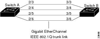
This sample configuration shows how to configure an 802.1Q trunk over a Gigabit EtherChannel link between two switches with 802.1Q-capable hardware. (Use the show port capabilities command to see if your hardware is 802.1Q-capable.)
Figure 11-1 shows two switches connected through four 1000BASE-SX Gigabit Ethernet ports.
Figure 11-1 IEEE 802.1Q Trunk over Gigabit EtherChannel Link
Note
To configure the switches to form a four-port Gigabit EtherChannel bundle, and then configure the EtherChannel bundle as an 802.1Q trunk link, follow these steps:
Step 1
Switch_A> (enable) set vlan 1 2/3-6VLAN Mod/Ports---- -----------------------1 2/3-6Switch_A> (enable)Switch_B> (enable) set vlan 1 3/3-6VLAN Mod/Ports---- -----------------------1 3/3-6Switch_B> (enable)Step 2
Switch_A> (enable) set trunk 2/3 desirable dot1qPort(s) 2/3-6 trunk mode set to desirable.Port(s) 2/3-6 trunk type set to dot1q.Switch_A> (enable) %DTP-5-TRUNKPORTON:Port 2/3 has become dot1q trunk%DTP-5-TRUNKPORTON:Port 2/4 has become dot1q trunk%ETHC-5-PORTFROMSTP:Port 2/3 left bridge port 2/3-6%DTP-5-TRUNKPORTON:Port 2/5 has become dot1q trunk%ETHC-5-PORTFROMSTP:Port 2/4 left bridge port 2/3-6%ETHC-5-PORTFROMSTP:Port 2/5 left bridge port 2/3-6%DTP-5-TRUNKPORTON:Port 2/6 has become dot1q trunk%ETHC-5-PORTFROMSTP:Port 2/6 left bridge port 2/3-6%ETHC-5-PORTFROMSTP:Port 2/3 left bridge port 2/3%ETHC-5-PORTTOSTP:Port 2/3 joined bridge port 2/3-6%ETHC-5-PORTTOSTP:Port 2/4 joined bridge port 2/3-6%ETHC-5-PORTTOSTP:Port 2/5 joined bridge port 2/3-6%ETHC-5-PORTTOSTP:Port 2/6 joined bridge port 2/3-6Switch_B> (enable) %DTP-5-TRUNKPORTON:Port 3/3 has become dot1q trunk%DTP-5-TRUNKPORTON:Port 3/4 has become dot1q trunk%ETHC-5-PORTFROMSTP:Port 3/3 left bridge port 3/3-6%ETHC-5-PORTFROMSTP:Port 3/4 left bridge port 3/3-6%ETHC-5-PORTFROMSTP:Port 3/5 left bridge port 3/3-6%ETHC-5-PORTFROMSTP:Port 3/6 left bridge port 3/3-6%DTP-5-TRUNKPORTON:Port 3/5 has become dot1q trunk%DTP-5-TRUNKPORTON:Port 3/6 has become dot1q trunk%ETHC-5-PORTFROMSTP:Port 3/5 left bridge port 3/3-6%ETHC-5-PORTFROMSTP:Port 3/6 left bridge port 3/3-6%ETHC-5-PORTTOSTP:Port 3/3 joined bridge port 3/3-6%ETHC-5-PORTTOSTP:Port 3/4 joined bridge port 3/3-6%ETHC-5-PORTTOSTP:Port 3/5 joined bridge port 3/3-6%ETHC-5-PORTTOSTP:Port 3/6 joined bridge port 3/3-6Step 3
Switch_A> (enable) show trunkPort Mode Encapsulation Status Native vlan-------- ----------- ------------- ------------ -----------2/3 desirable dot1q trunking 12/4 desirable dot1q trunking 12/5 desirable dot1q trunking 12/6 desirable dot1q trunking 1Port Vlans allowed on trunk-------- ---------------------------------------------------------------------2/3 1-1005, 1025-40942/4 1-1005, 1025-40942/5 1-1005, 1025-40942/6 1-1005, 1025-4094Port Vlans allowed and active in management domain-------- ---------------------------------------------------------------------2/3 1-1005, 1025-40942/4 1-1005, 1025-40942/5 1-1005, 1025-40942/6 1-1005, 1025-4094Port Vlans in spanning tree forwarding state and not pruned-------- ---------------------------------------------------------------------2/3 1-1005, 1025-40942/4 1-1005, 1025-40942/5 1-1005, 1025-40942/6 1-1005, 1025-4094Switch_A> (enable)Switch_B> (enable) show trunkPort Mode Encapsulation Status Native vlan-------- ----------- ------------- ------------ -----------3/3 auto dot1q trunking 13/4 auto dot1q trunking 13/5 auto dot1q trunking 13/6 auto dot1q trunking 1Port Vlans allowed on trunk-------- ---------------------------------------------------------------------3/3 1-1005, 1025-40943/4 1-1005, 1025-40943/5 1-1005, 1025-40943/6 1-1005, 1025-4094Port Vlans allowed and active in management domain-------- ---------------------------------------------------------------------3/3 1-1005, 1025-40943/4 1-1005, 1025-40943/5 1-1005, 1025-40943/6 1-1005, 1025-4094Port Vlans in spanning tree forwarding state and not pruned-------- ---------------------------------------------------------------------3/3 1-1005, 1025-40943/4 1-1005, 1025-40943/5 1-1005, 1025-40943/6 1-1005, 1025-4094Switch_B> (enable)Step 4
Switch_A> (enable) show port channelNo ports channellingSwitch_A> (enable) show trunkNo ports trunking.Switch_A> (enable)Switch_B> (enable) show port channelNo ports channellingSwitch_B> (enable) show trunkNo ports trunking.Switch_B> (enable)Step 5
Switch_A> (enable) set port channel 2/3-6 desirablePort(s) 2/3-6 channel mode set to desirable.Switch_A> (enable) %PAGP-5-PORTFROMSTP:Port 2/3 left bridge port 2/3%ETHC-5-PORTFROMSTP:Port 2/4 left bridge port 2/4%ETHC-5-PORTFROMSTP:Port 2/5 left bridge port 2/5%ETHC-5-PORTFROMSTP:Port 2/6 left bridge port 2/6%ETHC-5-PORTFROMSTP:Port 2/4 left bridge port 2/4%ETHC-5-PORTFROMSTP:Port 2/5 left bridge port 2/5%ETHC-5-PORTFROMSTP:Port 2/6 left bridge port 2/6%ETHC-5-PORTFROMSTP:Port 2/3 left bridge port 2/3%ETHC-5-PORTTOSTP:Port 2/3 joined bridge port 2/3-6%ETHC-5-PORTTOSTP:Port 2/4 joined bridge port 2/3-6%ETHC-5-PORTTOSTP:Port 2/5 joined bridge port 2/3-6%ETHC-5-PORTTOSTP:Port 2/6 joined bridge port 2/3-6Switch_B> (enable) %PAGP-5-PORTFROMSTP:Port 3/3 left bridge port 3/3%ETHC-5-PORTFROMSTP:Port 3/4 left bridge port 3/4%ETHC-5-PORTFROMSTP:Port 3/5 left bridge port 3/5%ETHC-5-PORTFROMSTP:Port 3/6 left bridge port 3/6%ETHC-5-PORTFROMSTP:Port 3/4 left bridge port 3/4%ETHC-5-PORTFROMSTP:Port 3/5 left bridge port 3/5%ETHC-5-PORTFROMSTP:Port 3/6 left bridge port 3/6%ETHC-5-PORTFROMSTP:Port 3/3 left bridge port 3/3%ETHC-5-PORTTOSTP:Port 3/3 joined bridge port 3/3-6%ETHC-5-PORTTOSTP:Port 3/4 joined bridge port 3/3-6%ETHC-5-PORTTOSTP:Port 3/5 joined bridge port 3/3-6%ETHC-5-PORTTOSTP:Port 3/6 joined bridge port 3/3-6Step 6
Switch_A> (enable) show port channelPort Status Channel Channel Neighbor Neighbormode status device port----- ---------- --------- ----------- ------------------------- ----------2/3 connected desirable channel WS-C4003 JAB023806(Sw 2/32/4 connected desirable channel WS-C4003 JAB023806(Sw 2/42/5 connected desirable channel WS-C4003 JAB023806(Sw 2/52/6 connected desirable channel WS-C4003 JAB023806(Sw 2/6----- ---------- --------- ----------- ------------------------- ----------Switch_A> (enable)Switch_B> (enable) show port channelPort Status Channel Channel Neighbor Neighbormode status device port----- ---------- --------- ----------- ------------------------- ----------3/3 connected auto channel WS-C4003 JAB023806(Sw 2/33/4 connected auto channel WS-C4003 JAB023806(Sw 2/43/5 connected auto channel WS-C4003 JAB023806(Sw 2/53/6 connected auto channel WS-C4003 JAB023806(Sw 2/6----- ---------- --------- ----------- ------------------------- ----------Switch_B> (enable)
Example of Load-Sharing VLAN Traffic over Parallel Trunks
Using spanning tree port-VLAN priorities, you can load-share VLAN traffic over parallel trunk ports so that traffic from some VLANs travels over one trunk, while traffic from other VLANs travels over the other trunk. This configuration allows traffic to be carried over both trunks simultaneously (instead of keeping one trunk in blocking mode), which reduces the total traffic carried over each trunk while still maintaining a fault-tolerant configuration.
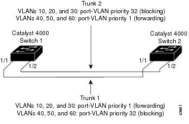
Figure 11-2 shows a parallel trunk configuration between two switches, using the Fast Ethernet uplink ports on the supervisor engine.
Figure 11-2 Parallel Trunk Configuration Before Configuring VLAN-Traffic Load Sharing
By default, the port-VLAN priority for both trunks is equal (a value of 32). Therefore, STP blocks port 1/2 (Trunk 2) for each VLAN on Switch 1 to prevent forwarding loops. Trunk 2 is not used to forward traffic unless Trunk 1 fails.
To configure the switches so that traffic from multiple VLANs is load balanced over the parallel trunks, follow these steps:
Step 1
Switch_1> (enable) set vtp domain BigCorp mode serverVTP domain BigCorp modifiedSwitch_1> (enable)Switch_2> (enable) set vtp domain BigCorp mode serverVTP domain BigCorp modifiedSwitch_2> (enable)Step 2
Switch_1> (enable) set vlan 10Vlan 10 configuration successfulSwitch_1> (enable) set vlan 20Vlan 20 configuration successfulSwitch_1> (enable) set vlan 30Vlan 30 configuration successfulSwitch_1> (enable) set vlan 40Vlan 40 configuration successfulSwitch_1> (enable) set vlan 50Vlan 50 configuration successfulSwitch_1> (enable) set vlan 60Vlan 60 configuration successfulSwitch_1> (enable)Step 3
Switch_1> (enable) show vtp domainDomain Name Domain Index VTP Version Local Mode Password-------------------------------- ------------ ----------- ----------- ----------BigCorp 1 2 server -Vlan-count Max-vlan-storage Config Revision Notifications---------- ---------------- --------------- -------------11 1023 13 disabledLast Updater V2 Mode Pruning PruneEligible on Vlans--------------- -------- -------- -------------------------172.20.52.10 disabled enabled 2-1000Switch_1> (enable) show vlanVLAN Name Status Mod/Ports, Vlans---- -------------------------------- --------- ----------------------------1 default active 1/1-22/1-125/1-210 VLAN0010 active11 VLAN0011 active20 VLAN0020 active30 VLAN0030 active40 VLAN0040 active50 VLAN0050 active60 VLAN0060 active1002 fddi-default active1003 token-ring-default active1004 fddinet-default active1005 trnet-default active...Switch_1> (enable)Step 4
Switch_1> (enable) set trunk 1/1 desirablePort(s) 1/1 trunk mode set to desirable.2000 Jul 12 01:56:28 %DTP-5-TRUNKPORTON:Port 1/1 has become dot1q trunkSwitch_1> (enable)Switch_1> (enable) set trunk 1/2 desirablePort(s) 1/2 trunk mode set to desirable.2000 Jul 12 01:56:52 %DTP-5-TRUNKPORTON:Port 1/2 has become dot1q trunkSwitch_1> (enable)Step 5
Switch_1> (enable) show trunk 1* - indicates vtp domain mismatchPort Mode Encapsulation Status Native vlan-------- ----------- ------------- ------------ -----------1/1 desirable dot1q trunking 11/2 desirable dot1q trunking 1Port Vlans allowed on trunk-------- ---------------------------------------------------------------------1/1 1-1005,1025-40941/2 1-1005,1025-4094Port Vlans allowed and active in management domain-------- ---------------------------------------------------------------------1/1 1,10,20,30,40,50,601/2 1,10,20,30,40,50,60Port Vlans in spanning tree forwarding state and not pruned-------- ---------------------------------------------------------------------1/1 1,10,20,30,40,50,601/2Switch_1> (enable)Step 6
Switch_2> (enable) show vlanVLAN Name Status Mod/Ports, Vlans---- -------------------------------- --------- ----------------------------1 default active10 VLAN0010 active20 VLAN0020 active30 VLAN0030 active40 VLAN0040 active50 VLAN0050 active60 VLAN0060 active1002 fddi-default active1003 token-ring-default active1004 fddinet-default active1005 trnet-default active...Switch_2> (enable)Step 7
Trunk 1 is forwarding for all VLANs. Trunk 2 is blocking for all VLANs. On Switch 2, both trunks are forwarding for all VLANs, but no traffic passes over Trunk 2 because port 1/2 on Switch 1 is blocking.
Switch_1> (enable) show spantree 1/1Port Vlan Port-State Cost Priority Fast-Start Group-method--------- ---- ------------- ----- -------- ---------- ------------1/1 1 forwarding 19 32 disabled1/1 10 forwarding 19 32 disabled1/1 20 forwarding 19 32 disabled1/1 30 forwarding 19 32 disabled1/1 40 forwarding 19 32 disabled1/1 50 forwarding 19 32 disabled1/1 60 forwarding 19 32 disabled1/1 1003 not-connected 19 32 disabled1/1 1005 not-connected 19 4 disabledSwitch_1> (enable) show spantree 1/2Port Vlan Port-State Cost Priority Fast-Start Group-method--------- ---- ------------- ----- -------- ---------- ------------1/2 1 blocking 19 32 disabled1/2 10 blocking 19 32 disabled1/2 20 blocking 19 32 disabled1/2 30 blocking 19 32 disabled1/2 40 blocking 19 32 disabled1/2 50 blocking 19 32 disabled1/2 60 blocking 19 32 disabled1/2 1003 not-connected 19 32 disabled1/2 1005 not-connected 19 4 disabledSwitch_1> (enable)Step 8
VLANs 10, 20, and 30 (Group 1) are forwarded over Trunk 1, and VLANs 40, 50, and 60 (Group 2) are forwarded over Trunk 2.
Step 9
Switch_1> (enable) set spantree portvlanpri 1/1 1 10Port 1/1 vlans 1-9,11-1004 using portpri 32.Port 1/1 vlans 10 using portpri 1.Port 1/1 vlans 1005 using portpri 4.Switch_1> (enable) set spantree portvlanpri 1/1 1 20Port 1/1 vlans 1-9,11-19,21-1004 using portpri 32.Port 1/1 vlans 10,20 using portpri 1.Port 1/1 vlans 1005 using portpri 4.Switch_1> (enable) set spantree portvlanpri 1/1 1 30Port 1/1 vlans 1-9,11-19,21-29,31-1004 using portpri 32.Port 1/1 vlans 10,20,30 using portpri 1.Port 1/1 vlans 1005 using portpri 4.Switch_1> (enable)Step 10
Switch_1> (enable) set spantree portvlanpri 1/2 1 40Port 1/2 vlans 1-39,41-1004 using portpri 32.Port 1/2 vlans 40 using portpri 1.Port 1/2 vlans 1005 using portpri 4.Switch_1> (enable) set spantree portvlanpri 1/2 1 50Port 1/2 vlans 1-39,41-49,51-1004 using portpri 32.Port 1/2 vlans 40,50 using portpri 1.Port 1/2 vlans 1005 using portpri 4.Switch_1> (enable) set spantree portvlanpri 1/2 1 60Port 1/2 vlans 1-39,41-49,51-59,61-1004 using portpri 32.Port 1/2 vlans 40,50,60 using portpri 1.Port 1/2 vlans 1005 using portpri 4.Switch_1> (enable)Step 11
Caution
Switch_2> (enable) set spantree portvlanpri 1/1 1 10Port 1/1 vlans 1-9,11-1004 using portpri 32.Port 1/1 vlans 10 using portpri 1.Port 1/1 vlans 1005 using portpri 4.Switch_2> (enable) set spantree portvlanpri 1/1 1 20Port 1/1 vlans 1-9,11-19,21-1004 using portpri 32.Port 1/1 vlans 10,20 using portpri 1.Port 1/1 vlans 1005 using portpri 4.Switch_2> (enable) set spantree portvlanpri 1/1 1 30Port 1/1 vlans 1-9,11-19,21-29,31-1004 using portpri 32.Port 1/1 vlans 10,20,30 using portpri 1.Port 1/1 vlans 1005 using portpri 4.Switch_2> (enable)Step 12
Switch_2> (enable) set spantree portvlanpri 1/2 1 40Port 1/2 vlans 1-39,41-1004 using portpri 32.Port 1/2 vlans 40 using portpri 1.Port 1/2 vlans 1005 using portpri 4.Switch_2> (enable) set spantree portvlanpri 1/2 1 50Port 1/2 vlans 1-39,41-49,51-1004 using portpri 32.Port 1/2 vlans 40,50 using portpri 1.Port 1/2 vlans 1005 using portpri 4.Switch_2> (enable) set spantree portvlanpri 1/2 1 60Port 1/2 vlans 1-39,41-49,51-59,61-1004 using portpri 32.Port 1/2 vlans 40,50,60 using portpri 1.Port 1/2 vlans 1005 using portpri 4.Switch_2> (enable)Step 13
Check the spanning tree port states on Switch 1 by entering the show spantree command. The Group 1 VLANs should be forwarding on Trunk 1 and blocking on Trunk 2. The Group 2 VLANs should be blocking on Trunk 1 and forwarding on Trunk 2.
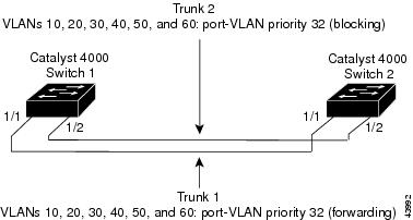
Switch_1> (enable) show spantree 1/1Port Vlan Port-State Cost Priority Fast-Start Group-method--------- ---- ------------- ----- -------- ---------- ------------1/1 1 forwarding 19 32 disabled1/1 10 forwarding 19 1 disabled1/1 20 forwarding 19 1 disabled1/1 30 forwarding 19 1 disabled1/1 40 blocking 19 32 disabled1/1 50 blocking 19 32 disabled1/1 60 blocking 19 32 disabled1/1 1003 not-connected 19 32 disabled1/1 1005 not-connected 19 4 disabledSwitch_1> (enable) show spantree 1/2Port Vlan Port-State Cost Priority Fast-Start Group-method--------- ---- ------------- ----- -------- ---------- ------------1/2 1 blocking 19 32 disabled1/2 10 blocking 19 32 disabled1/2 20 blocking 19 32 disabled1/2 30 blocking 19 32 disabled1/2 40 forwarding 19 1 disabled1/2 50 forwarding 19 1 disabled1/2 60 forwarding 19 1 disabled1/2 1003 not-connected 19 32 disabled1/2 1005 not-connected 19 4 disabledSwitch_1> (enable)Figure 11-3 shows the network after you configure VLAN traffic load-sharing.
Figure 11-3 Parallel Trunk Configuration after Configuring VLAN Traffic Load-Sharing
Figure 11-3 shows that both trunks are utilized when the network is operating normally and, if one trunk link fails, the other trunk link acts as an alternate forwarding path for the traffic previously traveling over the failed link.
If Trunk 1 fails in the network shown in Figure 11-3, STP reconverges to use Trunk 2 to forward traffic from all the VLANs, as shown in the following example:
Switch_1> (enable) 04/21/1998,03:15:40:ETHC-5:Port 1/1 has become non-trunkSwitch_1> (enable) show spantree 1/1Port Vlan Port-State Cost Priority Fast-Start Group-method--------- ---- ------------- ----- -------- ---------- ------------1/1 1 not-connected 19 32 disabledSwitch_1> (enable) show spantree 1/2Port Vlan Port-State Cost Priority Fast-Start Group-method--------- ---- ------------- ----- -------- ---------- ------------1/2 1 learning 19 32 disabled1/2 10 learning 19 32 disabled1/2 20 learning 19 32 disabled1/2 30 learning 19 32 disabled1/2 40 forwarding 19 1 disabled1/2 50 forwarding 19 1 disabled1/2 60 forwarding 19 1 disabled1/2 1003 not-connected 19 32 disabled1/2 1005 not-connected 19 4 disabledSwitch_1> (enable) show spantree 1/2Port Vlan Port-State Cost Priority Fast-Start Group-method--------- ---- ------------- ----- -------- ---------- ------------1/2 1 forwarding 19 32 disabled1/2 10 forwarding 19 32 disabled1/2 20 forwarding 19 32 disabled1/2 30 forwarding 19 32 disabled1/2 40 forwarding 19 1 disabled1/2 50 forwarding 19 1 disabled1/2 60 forwarding 19 1 disabled1/2 1003 not-connected 19 32 disabled1/2 1005 not-connected 19 4 disabledSwitch_1> (enable)Example of an 802.1Q Nonegotiate Trunk Configuration
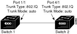
This sample configuration shows how to configure an 802.1Q Fast Ethernet trunk between two Catalyst 4000 family switches with 802.1Q-capable hardware. (Use the show port capabilities command to see if your hardware is 802.1Q-capable). The initial network configuration is shown in Figure 11-4. Assume that the native VLAN is VLAN 1 on both ends of the link.
To configure an 802.1Q trunk between port 1/1 on Switch 1 and port 4/1 on Switch 2, follow these steps:
Figure 11-4 802.1Q Trunking: Initial Network Configuration
Step 1
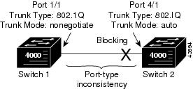
Switch 1> (enable) set trunk 1/1 nonegotiate dot1qPort(s) 1/1 trunk mode set to nonegotiate.Port(s) 1/1 trunk type set to dot1q.Switch 1> (enable) 04/15/1998,22:02:17:DISL-5:Port 1/1 has become dot1q trunkSwitch 2> (enable) 04/15/1998,22:01:42:SPANTREE-2: Rcved 1Q-BPDU on non-1Q-trunk port 4/1 vlan 1.04/15/1998,22:01:42:SPANTREE-2: Block 4/1 on rcving vlan 1 for inc trunk port.04/15/1998,22:01:42:SPANTREE-2: Block 4/1 on rcving vlan 1 for inc peer vlan 2.Switch 2> (enable)
Note
Figure 11-5 802.1Q Trunking: Port-Type Inconsistency
Step 2
Switch 2> (enable) show spantree 1VLAN 1Spanning tree enabledSpanning tree type ieeeDesignated Root 00-60-09-79-c3-00Designated Root Priority 32768Designated Root Cost 0Designated Root Port 1/0Root Max Age 20 sec Hello Time 2 sec Forward Delay 15 secBridge ID MAC ADDR 00-60-09-79-c3-00Bridge ID Priority 32768Bridge Max Age 20 sec Hello Time 2 sec Forward Delay 15 secPort Vlan Port-State Cost Priority Fast-Start Group-method--------- ---- ------------- ----- -------- ---------- ------------1/1 1 not-connected 4 32 disabled1/2 1 not-connected 4 32 disabled4/1 1 type-pvid-inconsistent 100 32 disabled4/2 1 not-connected 100 32 disabled<...output truncated...>Switch 2> (enable) show spantree statistics 4/1Port 4/1 VLAN 1SpanningTree enabled for vlanNo = 1BPDU-related parametersport spanning tree enabledstate brokenport_id 0x8142port number 0x142path cost 100message age (port/VLAN) 1(20)designated_root 00-60-09-79-c3-00designated_cost 0designated_bridge 00-60-09-79-c3-00designated_port 0x8142top_change_ack FALSEconfig_pending FALSEport_inconsistency port_type & port_vlan<...output truncated...>Switch 2> (enable)Step 3
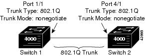
Switch 2> (enable) set trunk 4/1 nonegotiate dot1qPort(s) 4/1 trunk mode set to nonegotiate.Port(s) 4/1 trunk type set to dot1q.Switch 2> (enable) 2/20/1998,23:41:15:DISL-5:Port 4/1 has become dot1q trunkPort 4/1 on Switch 2 changes from blocking mode to forwarding mode once the port-type inconsistency is resolved (see Figure 11-6). (This assumes that there is no wiring loop present that would cause the port to be blocked normally by spanning tree. In either case, the port state would change from "type-pvid-inconsistent" to "blocking" in the show spantree output.)
Figure 11-6 802.1Q Trunking: Final Network Configuration
Step 4
Switch 1> (enable) show trunk 1/1Port Mode Encapsulation Status Native vlan-------- ----------- ------------- ------------ -----------1/1 nonegotiate dot1q trunking 1Port Vlans allowed on trunk-------- ---------------------------------------------------------------------1/1 1-1005, 1025-4094Port Vlans allowed and active in management domain-------- ---------------------------------------------------------------------1/1 1-3,1003,1005Port Vlans in spanning tree forwarding state and not pruned-------- ---------------------------------------------------------------------1/1 1005Switch 1> (enable) show spantree 1VLAN 1Spanning tree enabledSpanning tree type ieeeDesignated Root 00-60-09-79-c3-00Designated Root Priority 32768Designated Root Cost 0Designated Root Port 1/1Root Max Age 20 sec Hello Time 2 sec Forward Delay 15 secBridge ID MAC ADDR 00-10-29-b5-30-00Bridge ID Priority 49152Bridge Max Age 20 sec Hello Time 2 sec Forward Delay 15 secPort Vlan Port-State Cost Priority Fast-Start Group-method--------- ---- ------------- ----- -------- ---------- ------------1/1 1 forwarding 4 32 disabled1/2 1 not-connected 4 32 disabled<...output truncated...>Switch 1> (enable)The output shows that port 1/1 is an 802.1Q trunk port, that its status is "trunking," and that the port-state is "forwarding."
Step 5
Switch 2> (enable) show trunk 4/1Port Mode Encapsulation Status Native vlan-------- ----------- ------------- ------------ -----------4/1 nonegotiate dot1q trunking 1Port Vlans allowed on trunk-------- ---------------------------------------------------------------------4/1 1-1005, 1025-4094Port Vlans allowed and active in management domain-------- ---------------------------------------------------------------------4/1 1-3,1003,1005Port Vlans in spanning tree forwarding state and not pruned-------- ---------------------------------------------------------------------4/1 1005Switch 2> (enable) show spantree 1VLAN 1Spanning tree enabledSpanning tree type ieeeDesignated Root 00-60-09-79-c3-00Designated Root Priority 32768Designated Root Cost 0Designated Root Port 1/0Root Max Age 20 sec Hello Time 2 sec Forward Delay 15 secBridge ID MAC ADDR 00-60-09-79-c3-00Bridge ID Priority 32768Bridge Max Age 20 sec Hello Time 2 sec Forward Delay 15 secPort Vlan Port-State Cost Priority Fast-Start Group-method--------- ---- ------------- ----- -------- ---------- ------------1/1 1 not-connected 4 32 disabled1/2 1 not-connected 4 32 disabled4/1 1 forwarding 100 32 disabled4/2 1 not-connected 100 32 disabled<...output truncated...>Switch 2> (enable)The output shows that port 4/1 is an 802.1Q trunk port, that its status is "trunking," and that the port-state is "forwarding."
Step 6
Switch 1> (enable) ping switch_2switch_2 is aliveSwitch 1> (enable)
Disabling VLAN1 on a Trunk Link
On the Catalyst enterprise LAN switches, VLAN 1 is enabled by default to allow control protocols to transmit and receive packets across the network topology. However, when VLAN 1 is enabled on trunk links in a large complex network topology, the impact of broadcast storms increases. Because spanning tree applies to the entire network topology, the possibility of spanning tree loops also increases when VLAN 1 is enabled on all trunk links. To prevent this situation, you can disable VLAN 1 on trunk interfaces.
When you disable VLAN 1 on a trunk interface, no user traffic is transmitted or received across that trunk interface, but the supervisor engine will continue to transmit and receive packets from control protocols such as Cisco Discovery Protocol (CDP), VLAN Trunking Protocol (VTP), Port Aggregation Protocol (PAgP), Dynamic Trunking Protocol (DTP), and so forth.
Caution
When a trunk port with VLAN 1 disabled becomes a nontrunk port, it is added to the native VLAN. If the native VLAN is VLAN 1, the port is enabled and added to VLAN 1.
To disable VLAN 1 on a trunk interface, perform this task in privileged mode:
Step 1
Disable VLAN 1 on the trunk interface.
clear trunk mod_num/port_num [vlan-range]
Step 2
Verify the allowed VLAN list for the trunk.
show trunk [mod_num/port_num]
This example shows how to disable VLAN 1 on a trunk link and verify the configuration:
Console> (enable) clear trunk 4/1 1Removing Vlan(s) 1 from allowed list.Port 4/1 allowed vlans modified to 2-1005. Console> (enable) show trunk 4/1Port Mode Encapsulation Status Native vlan-------- ----------- ------------- ------------ -----------4/1 on isl trunking 1Port Vlans allowed on trunk-------- ---------------------------------------------------------------------4/1 2-999, 1025-4094Port Vlans allowed and active in management domain-------- ---------------------------------------------------------------------4/1 2-6,10,20,50,100,152,200,300,400,500,521,524,570,776,801-802,850,917,999Port Vlans in spanning tree forwarding state and not pruned-------- ---------------------------------------------------------------------4/1 2-6,10,20,50,100,152,200,300,400,500,521,524,570,776,802,850,917,999Console> (enable)