-
Catalyst 4500 Series Software Configuration Guide, 7.5
-
Preface
-
Product Overview
-
Using the Command-Line Interface
-
Configuring the Switch IP Address and Default Gateway
-
Configuring Ethernet and Fast Ethernet Switching
-
Configuring Gigabit Ethernet Switching
-
Configuring Fast EtherChannel and Gigabit EtherChannel
-
Configuring Spanning Tree
-
Configuring Spanning Tree PortFast, BPDU Guard, BPDU Filter, UplinkFast, BackboneFast, and Loop Guard
-
Configuring VTP
-
Configuring VLANs
-
Configuring VLAN Trunks on Fast Ethernet and Gigabit Ethernet Ports
-
Configuring Dynamic VLAN Membership with VMPS
-
Configuring GVRP
-
Configuring QoS
-
Configuring Multicast Services
-
Configuring Port Security
-
Configuring Unicast Flood Blocking
-
Configuring the IP Permit List
-
Configuring Protocol Filtering
-
Checking Port Status and Connectivity
-
Configuring CDP
-
Using Switch TopN Reports
-
Configuring UDLD
-
Configuring SNMP
-
Configuring RMON
-
Configuring SPAN and RSPAN
-
Administering the Switch
-
Configuring Switch Access Using AAA
-
Modifying the Switch Boot Configuration
-
Working with System Software Images
-
Using the Flash File System
-
Working with Configuration Files
-
Configuring Switch Acceleration
-
Configuring System Message Logging
-
Configuring DNS
-
Configuring NTP
-
Glossary
-
Index
-
 Feedback
Table Of Contents
How a Switch or Port Becomes the Root Switch or Root Port
Calculating and Assigning Port Costs
Calculating the Port Cost Using the Short Method
Calculating the Port Cost Using the Long Method
Calculating the Port Cost for Aggregate Links
How Spanning Tree Port States Work
Understanding PVST+ and MISTP Modes
Configuring PVST+ Bridge ID Priority
Configuring PVST+ Port Priority
Configuring PVST+ Default Port Cost Mode
Configuring PVST+ Port VLAN Cost
Configuring PVST+ Port VLAN Priority
Disabling the PVST+ Mode on a VLAN
Configuring MISTP Bridge ID Priority
Configuring MISTP Port Priority
Configuring MISTP Port Instance Cost
Configuring MISTP Port Instance Priority
Mapping VLANs to an MISTP Instance
Determining MISTP Instance—VLAN Mapping Conflicts
Unmapping VLANs from an MISTP Instance
Disabling MISTP-PVST+ or MISTP
Configuring a Primary Root Switch
Configuring a Secondary Root Switch
Configuring a Root Switch to Improve Convergence
Using Root Guard—Preventing Switches from Becoming Root
Configuring Spanning Tree Timers
Configuring Forward Delay Time
Configuring Maximum Aging Time
Understanding How BPDU Skewing Works
Configuring Spanning Tree BPDU Skewing
Configuring the MST Bridge ID Priority
Configuring the MST Port Priority
Configuring the MST Port Instance Cost
Configuring the MST Port Instance Priority
Mapping and Unmapping VLANs to an MST Instance
Configuring Spanning Tree
This chapter provides a brief overview of the IEEE 802.1D bridge Spanning Tree Protocol (STP) and describes how to use and configure the Cisco proprietary STPs, Per VLAN Spanning Tree + (PVST+), and Multi-Instance Spanning Tree Protocol (MISTP) on the Catalyst enterprise LAN switches.
Note
For information on configuring the spanning tree PortFast, UplinkFast, and BackboneFast features, see "Configuring Spanning Tree PortFast, BPDU Guard, BPDU Filter, UplinkFast, BackboneFast, and Loop Guard."
This chapter consists of these major sections:
•
•
•
•
Note
How STPs Work
This section describes the specific functions that are common to all spanning tree protocols. The Cisco proprietary spanning tree protocols, PVST+ and MISTP, are based on the IEEE 802.1D STP. (See the "Understanding PVST+ and MISTP Modes" section for information about PVST+ and MISTP.) The 802.1D STP is a Layer 2 management protocol that provides path redundancy in a network while preventing undesirable loops. All spanning tree protocols use an algorithm that calculates the best loop-free path through the network.
STP uses a distributed algorithm that selects one bridge of a redundantly connected network as the root of a spanning tree connected active topology. STP assigns roles to each port depending on what the port's function is in the active topology. Port roles are as follows:
•
•
•
•
Switches that have ports with these assigned roles are called root or designated switches. For more information, see the "How a Topology Is Created" section.
In Ethernet networks, only one active path may exist between any two stations. Multiple active paths between stations can cause loops in the network. When loops occur, some switches recognize stations on both sides of the switch. This situation causes the forwarding algorithm to malfunction allowing duplicate frames to be forwarded.
Spanning tree algorithms provide path redundancy by defining a tree that spans all of the switches in an extended network and then forces certain redundant data paths into a standby (blocked) state. At regular intervals the switches in the network send and receive spanning tree packets which they use to identify the active path. If one network segment becomes unreachable, or if spanning tree costs change, the spanning tree algorithm reconfigures the spanning tree topology and reestablishes the link by activating a standby path.
Spanning tree operation is transparent to end stations, which do not detect whether they are connected to a single LAN segment or a switched LAN of multiple segments.
How a Topology Is Created
All switches in an extended LAN participating in a spanning tree gather information about other switches in the network through an exchange of data messages known as bridge protocol data units (BPDUs). This exchange of messages results in the following actions:
•
•
•
The following three things determine the topology of an active switched network:
•
•
•
In a switched network, the root switch is the logical center of the spanning tree topology. A spanning tree protocol uses BPDUs to elect the root switch and root port for the switched network, as well as the root port and designated port for each switched segment.
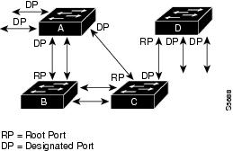
How a Switch or Port Becomes the Root Switch or Root Port
If all switches in a network are enabled with default settings, the switch with the lowest MAC address becomes the root switch. In the network shown in Figure 7-1, Switch A, with the lowest MAC address, is the root switch. However, due to traffic patterns, number of forwarding ports, or line types, Switch A might not be the ideal root switch. You can force a switch to become the root switch by increasing the priority (that is, lowering the priority number) on the preferred switch. This causes the spanning tree to recalculate the topology and make the selected switch the root switch.
Figure 7-1 Configuring a Loop-Free Topology
You can also change the priority of a port in order to make it the root port. When the spanning tree topology is based on default parameters, the path between source and destination stations in a switched network might not be ideal. The goal is to make the fastest link the root port, connecting higher-speed links to a port that has a higher number than the current root port can cause a root-port change.
For example, assume that a port on Switch B is a fiber-optic link. Also, another port on Switch B (an unshielded twisted-pair [UTP] link) is the root port. Network traffic might be more efficient over the high-speed fiber-optic link. By changing the Port Priority parameter for the UTP port to a higher priority (lower numerical value) than the fiber-optic port, the UTP port becomes the root port. You could also accomplish this scenario by changing the port cost parameter for the UTP port to a lower value than that of the fiber-optic port.
How BPDUs Work
BPDUs contain configuration information about the transmitting switch and its ports, including switch and port MAC addresses, switch priority, port priority, and port cost. Each configuration BPDU contains this information:
•
•
•
The switch sends configuration BPDUs to communicate with and compute the spanning tree topology. A MAC frame conveying a BPDU sends the switch group address to the destination address field. All switches connected to the LAN on which the frame is transmitted receive the BPDU. BPDUs are not directly forwarded by the switch, but the receiving switch uses the information in the frame to calculate a BPDU and, if the topology changes, initiates a BPDU transmission.
A BPDU exchange results in the following:
•
•
•
•
•
Calculating and Assigning Port Costs
By calculating and assigning the port cost of the switch ports, you can ensure that the shortest (lowest cost) distance to the root switch is used to transmit data. You can calculate and assign lower path cost values (port costs) to higher bandwidth ports by using either the short method (which is the default) or the long method. The short method uses a 16-bit format that yields values from 1 to 65535. The long method uses a 32-bit format that yields values in the range of 1 to 200,000,000. For more information on setting the default cost mode, see the "Configuring PVST+ Default Port Cost Mode" section.
Note
Calculating the Port Cost Using the Short Method
The IEEE 802.1D specification assigns 16-bit (short) default port cost values to each port that is based on bandwidth. You can also manually assign port costs between 1-65535. The 16-bit values are only used for ports that have not been specifically configured for port cost. Table 7-1 shows the default port cost values that are assigned by the switch for each type of port when you use the short method to calculate the port cost.
Table 7-1 Default Port Cost Values Using the Short Method
10 Mbps
100
1 to 65535
100 Mbps
19
1 to 65535
1 Gbps
4
1 to 65535
Calculating the Port Cost Using the Long Method
802.1t assigns 32-bit (long) default port cost values to each port using a formula that is based on the bandwidth of the port. You can also manually assign port costs between 1-200,000,000. The formula for obtaining default 32-bit port costs is to divide the bandwidth of the port by 200,000,000. Table 7-2 shows the default port cost values that are assigned by the switch and the recommended cost values and ranges for each type of port when you use the long method to calculate port cost.
Calculating the Port Cost for Aggregate Links
As individual links are added or removed from an aggregate link (port bundle), the bandwidth of the aggregate link increases or decreases. These changes in bandwidth lead to recalculation of the default port cost for the aggregated port. Changes to the default port cost or changes resulting from links that autonegotiate their bandwidth could lead to recalculation of the spanning tree topology which may not be desirable, especially if the added or removed link is of little consequence to the bandwidth of the aggregate link (for example, if a 10-Mbps link is removed from a 10-Gbps aggregate link). Because of the limitations that are presented by automatically recalculating the topology, 802.1t states that changes in bandwidth will not result in changes to the cost of the port. Therefore, the aggregated port will use the same port cost parameters as a standalone port.
How Spanning Tree Port States Work
Topology changes can take place in a switched network due to a link coming up or going down (failing). When a switch port transitions directly from nonparticipation in the topology to the forwarding state, it can create temporary data loops. Ports must wait for new topology information to propagate through the switches in the LAN before they can start forwarding frames. They must also allow the frame lifetime to expire for frames that have been forwarded using the old topology.
At any given time, each port on a switch using STP is in one of these states:
•
•
•
•
•
A port moves through these states:
•
•
•
•
•
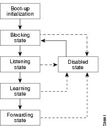
Figure 7-2 illustrates how a port moves through the states.
Figure 7-2 STP Port States
You can modify each port state by using management software, such as the VLAN Trunking Protocol (VTP). When you enable spanning tree, every switch in the network goes through the blocking state and the transitory states of listening and learning at power up. If properly configured, each port stabilizes into the forwarding or blocking state.
When the spanning tree algorithm places a port in the forwarding state, the following occurs:
•
•
•
•
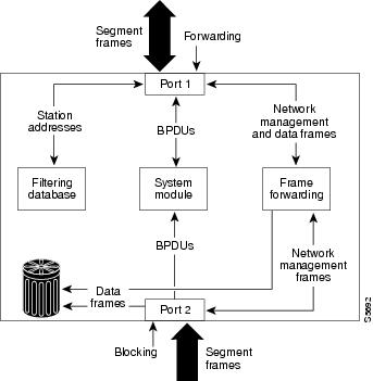
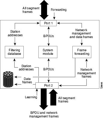
Blocking State
A port in the blocking state, such as Port 2 in Figure 7-3, does not participate in frame forwarding. After initialization, a BPDU is sent to each port in the switch. A switch initially assumes it is the root until it exchanges BPDUs with other switches. This exchange establishes which switch in the network is really the root. If only one switch resides in the network, no exchange occurs, the forward delay timer expires, and the ports move to the listening state. A switch always enters the blocking state following switch initialization.
Figure 7-3 Port 2 in Blocking State
A port in the blocking state performs as follows:
•
•
•
•
•
•
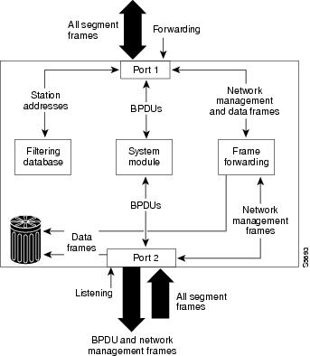
Listening State
The listening state is the first transitional state a port enters after the blocking state. The port enters this state when the spanning tree determines that the port should participate in frame forwarding. Learning is disabled in the listening state. Figure 7-4 shows a port in the listening state.
Figure 7-4 Port 2 in Listening State
A port in the listening state performs as follows:
•
•
•
•
•
•
Learning State
A port in the learning state prepares to participate in frame forwarding. The port enters the learning state from the listening state. Figure 7-5 shows a port in the learning state.
Figure 7-5 Port 2 in Learning State
A port in the learning state performs as follows:
•
•
•
•
•
•
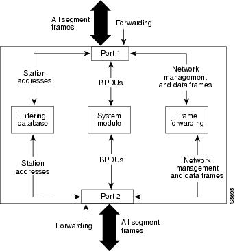
Forwarding State
A port in the forwarding state forwards frames, as shown in Figure 7-6. The port enters the forwarding state from the learning state.
Figure 7-6 Port 2 in Forwarding State
A port in the forwarding state performs as follows:
•
•
•
•
•
•
Caution
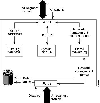
Disabled State
A port in the disabled state does not participate in frame forwarding or STP, as shown in Figure 7-7. A port in the disabled state is virtually nonoperational.
Figure 7-7 Port 2 in Disabled State
A disabled port performs as follows:
•
•
•
•
•
•
Understanding PVST+ and MISTP Modes
Catalyst 4000 family switches provide two proprietary spanning tree modes based on the IEEE 802.1D standard and one mode that is a combination of the two modes:
•
•
•
•
An overview of each mode is provided in this section. Each mode is described in detail in these sections:
Caution
PVST+ Mode
PVST+ is the default STP used on all Ethernet, Fast Ethernet, and Gigabit Ethernet port-based VLANs on Catalyst 4000 family switches. PVST+ runs on each VLAN on the switch, ensuring that each has a loop-free path through the network.
PVST+ provides Layer 2 load balancing for the VLAN on which it runs; you can create different logical topologies using the VLANs on your network to ensure that all of your links will be used but no one link will be oversubscribed.
Each instance of PVST+ on a VLAN has a single root switch. This root switch propagates the spanning tree information associated with that VLAN to all other switches in the network. Because each switch has the same knowledge about the network, this process ensures that the network topology is maintained.
Rapid PVST+
Rapid PVST+ is the same as PVST+, except that Rapid PVST+ utilizes a Rapid STP based on IEEE 802.1w instead of 802.1D. Rapid PVST+ uses the same configuration as PVST+, and you need only minimal extra configuration. With Rapid PVST+, dynamic CAM entries are flushed immediately on a per-port basis upon any topology change. UplinkFast and BackboneFast are enabled but not active in this mode, because the functionality is built into the rapid STP. This method provides for quick recovery of connectivity following the failure of a bridge, bridge port, or LAN.
MISTP Mode
MISTP is an optional STP that runs on Catalyst 4000 family switches. MISTP allows you to group multiple VLANs under a single instance of spanning tree (an MISTP instance). MISTP combines the Layer 2 load-balancing benefits of PVST+ with the lower CPU load of IEEE 802.1Q.
An MISTP instance is a virtual logical topology defined by a set of bridge and port parameters; an MISTP instance becomes a real topology when VLANs are mapped to it. Each MISTP instance has its own root switch and a different set of forwarding links (that is different bridge and port parameters).
Each instance of MISTP has a single root switch. This root switch propagates the information associated with that instance of MISTP to all other switches in the network. This process ensures that the network topology is maintained because each switch has the same knowledge about the network.
MISTP builds MISTP instances by exchanging MISTP BPDUs with peer entities in the network. There is only one BPDU for each MISTP instance, rather than for each VLAN as in PVST+. There are fewer BPDUs in an MISTP network; therefore, there is less overhead in the network. MISTP discards any PVST+ BPDUs that it sees.
An MISTP instance can have any number of VLANs mapped to it, but a VLAN can only be mapped to a single MISTP instance. You can easily move a VLAN (or VLANs) in an MISTP topology to another MISTP instance if it has converged. (However, if ports are added at the same time the VLAN is moved, convergence time is required.)
MISTP-PVST+ Mode
MISTP-PVST+ is a transition spanning tree mode that allows you to use the MISTP functionality on Catalyst 4000 family switches while continuing to communicate with the older Catalyst 5000 familyand 6500 series switches in your network that use PVST+. A switch using PVST+ mode and a switch using MISTP mode connected together cannot see the BPDUs of the other switch, a condition that can cause loops in the network. MISTP-PVST+ allows interoperability between PVST+ and pure MISTP, because it detects the BPDUs of both modes. If you wish to convert your network to MISTP, you can use MISTP-PVST+ to transition the network from PVST+ to MISTP in order to avoid problems.
MISTP-PVST+ conforms to the limits of PVST+; for example, you can only configure the amount of VLAN ports on your MISTP-PVST+ switches that you configure on your PVST+ switches.
Bridge Identifiers
The next two sections explain how MAC addresses are used in PVST+ and MISTP as unique bridge identifiers.
MAC Address Allocation
Catalyst 4000 series switches have a pool of 1024 MAC addresses that can be used as bridge identifiers for VLANs running under PVST+ or for MISTP instances. The Catalyst 4500 series switches have a pool of only 64 MAC addresses. You can use the show module command to view the MAC address range.
MAC addresses are allocated sequentially, with the first MAC address in the range assigned to VLAN 1, the second in the range assigned to VLAN 2, and so forth. The last MAC address in the range is assigned to the supervisor engine in-band (sc0) management interface.
For example, if the MAC address range for the supervisor engine is 00-e0-1e-9b-2e-00 to 00-e0-1e-9b-31-ff, the VLAN 1 bridge ID is 00-e0-1e-9b-2e-00, the VLAN 2 bridge ID is 00-e0-1e-9b-2e-01, the VLAN 3 bridge ID is 00-e0-1e-9b-2e-02, and so forth. The in-band (sc0) interface MAC address is 00-e0-1e-9b-31-ff.
MAC Address Reduction
The MAC address reduction feature is used on Catalyst 6000 family switches to enable extended-range VLAN identification. If you have a Catalyst 6000 switch in your network and you have MAC address reduction enabled on it, you should also enable MAC address reduction on all your Catalyst 4000 family switches to avoid problems in the spanning tree topology. When MAC address reduction is enabled on Catalyst 4000 family switches, it disables the pool of MAC addresses used for the VLAN spanning tree, leaving a single MAC address that identifies the switch. For detailed information on the MAC address reduction feature, refer to the Catalyst 6000 Family Software Configuration Guide.
MAC address reduction is always enabled on the Catalyst 4500 series switches; however, it may or may not be enabled on a Catalyst 4006 switch; this can affect the selection of the root bridge after you migrate your supervisor engine. Here are two scenarios to consider:
•
In this case, the spanning tree topology will not change. If you add to the network a Catalyst 4500 series switch with MAC-reduction enabled and its default spanning tree bridge ID priority set to 32,768, the bridge ID priority of the new switch becomes the bridge ID priority added to the system ID extension. The system ID extension is the VLAN number and can vary from 1 to 4094. So if the switch is in VLAN 1, the new bridge ID priority will be 32,769. Since 32,769 is greater than 32,768, this switch cannot become the root switch and poses no problems.
•
In this case, the spanning tree topology might change. If the other switches in the network are not running MAC-reduction, then the topology will change after you replace the chassis with a Catalyst 4500 series switch. The bridge ID priority of the new Catalyst 4500 series switch increments in the same manner as in the previous scenario (bridge ID priority + VLAN number). Therefore, if the switch is in VLAN 1, the new bridge ID will be 32769. Since 32769 is greater than 32768, this switch cannot become the root switch. The network designates a new root switch; the spanning tree topology also changes to reflect the new root switch.
If the bridge priority of the Catalyst 4006 has been lowered administratively and you use the same configuration in the new Catalyst 4500 series switch, then the switch remains the root switch and the spanning tree topology does not change.
For more information on migrating your supervisor engine from a Catalyst 4006 switch to a Catalyst 4500 series switch, see the "Migrating a Supervisor II from a Catalyst 4006 Switch to a Catalyst 4500 Series Switch" section.
Understanding How MST Works
The Multiple Spanning Tree (MST) feature is an upcoming IEEE standard: 802.1s for MST is an amendment to 802.1Q. MST extends the 802.1w Rapid Spanning Tree (RST) algorithm to multiple spanning trees. This extension provides for both rapid convergence and load balancing in a VLAN environment. The MST protocol is currently being further developed and the MST feature for this release is based on a draft version of the IEEE standard. The protocol as implemented in this release is backward compatible with 802.1D STP, 802.1w, the Rapid Spanning Tree Protocol (RSTP), and the Cisco PVST+ architecture.
MST allows you to build multiple spanning trees over VLAN trunks. You can group and associate VLANs to spanning tree instances. Each instance can have a topology independent of other spanning tree instances. This new architecture provides multiple forwarding paths for data traffic and enables load balancing. Network fault tolerance is improved because a failure in one instance (forwarding path) does not affect other instances (forwarding paths).
In large networks, having different VLAN-spanning tree instance assignments located in different parts of the network makes it easier to administrate and optimally utilize redundant paths. However, a spanning tree instance can exist only on bridges that have compatible VLAN-instance assignments. Therefore, MST requires that you configure a set of bridges with the same MST configuration information, allowing them to participate in a given set of spanning tree instances. Interconnected bridges that have the same MST configuration are referred to as an MST region.
MST uses the modified RSTP version called the Multiple Spanning Tree Protocol (MSTP). The MST feature has these characteristics:
•
•
–
–
–
•
–
M-records are always encapsulated within MST BPDUs (MST BPDUs). The original spanning trees computed by MSTP are called M-trees. M-trees are active only within the MST region. M-trees merge with the IST at the boundary of the MST region and form the CST.
•
•
–
–
–
–
–
–
Keep the following guidelines in mind when using MST:
•
•
•
•
•
•
Rapid Spanning Tree Protocol
RSTP significantly reduces the time it takes you to reconfigure the active topology of the network when changes to the physical topology or its configurations parameters occur. RSTP selects one switch as the root of a spanning-tree-connected active topology and assigns port roles to individual ports of the switch, depending on whether that port is part of the active topology.
RSTP provides rapid connectivity following the failure of a switch, switch port, or a LAN. A new root port and the designated port on the other side of the bridge transition to forwarding through an explicit handshake between them. RSTP allows switch port configuration so the ports can transition to forwarding directly when the switch reinitializes.
RSTP, specified in 802.1w, supersedes STP specified in 802.1D while retaining compatibility with STP. RSTP provides the structure on which the MST operates. You configure RSTP when you configure the MST feature. For more information, see the "Configuring MST" section.
RSTP provides backward compatibility with 802.1D bridges, as follows:
•
•
•
•
RSTP Port Roles
RSTP uses the following definitions for port roles:
•
•
•
•
•
Port roles are assigned as follows:
•
•
RSTP Port States
The port state controls the forwarding and learning processes and provides the values of discarding, learning, and forwarding. Table 7-3 provides a comparison between STP port states and RSTP port states.
Table 7-3 Comparison Between STP and RSTP Port States
Enabled
Blocking1
Discarding2
No
Enabled
Listening
Discarding
No
Enabled
Learning
Learning
Yes
Enabled
Forwarding
Forwarding
Yes
Disabled
Disabled
Discarding
No
1 IEEE 802.1D port state designation.
2 IEEE 802.1w port state designation.Discarding is analogous with, and the same as blocking in MST in this document.
In a stable topology, RSTP ensures that every root port and designated port transition to forwarding while all alternate ports and backup ports are always in the discarding state.
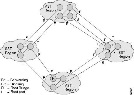
MST-to-SST Interoperability
A virtual bridged LAN may contain interconnected regions of SST and MST bridges. Figure 7-8 shows this relationship.
Figure 7-8 Network with Interconnected SST and MST Regions
To the spanning tree protocol running in the SST region, an MST region appears as a single SST or pseudo-bridge. Pseudo-bridges operate as follows:
•
–
–
•
•
•
–
–
•
Common Spanning Tree
802.1Q specifies a single spanning tree for all the VLANs called CST. In a Catalyst 4000 family switch running PVST+ the VLAN 1 spanning tree corresponds to CST, in a Catalyst 4000 family switch running MST, IST (instance 0) corresponds to CST.
MST Instances
This release supports up to 16 instances; each spanning tree instance is identified by an instance ID that ranges from 0 to 15. Instance 0 is mandatory and is always present. Instances 1 through 15 are optional.
MST Configuration
MST configuration has three parts as follows:
•
•
Note
•
You must configure each byte manually. You can use SNMP or the CLI to perform the configuration.
MST BPDUs contain the MST configuration ID and the checksum. An MST bridge accepts an MST BPDU only if the MST BPDU configuration ID and the checksum match its own MST region configuration ID and checksum. If one value is different, the MST BPDU is treated as an SST BPDU.
When you modify an MST configuration through either a console or Telnet connection, the session exits without committing those changes and the edit buffer locks. Further configuration is impossible until you discard the existing edit buffer and acquire a new edit buffer by entering the set spantree mst config rollback force command.
MST Region
Interconnected bridges that have the same MST configuration are referred to as an MST region. There is no limit on the number of MST regions in the network.
To form an MST region, bridges can be either of the following:
•
•
If you connect two MST regions with different MST configurations, the MST regions do the following:
•
•
Boundary Ports
A port that connects an MST region to an SST region running RSTP (802.1w), an SST region running STP (802.1D), or another MST region is a boundary port. A boundary port is a port that connects to a LAN, the designated bridge of which, is either an SST bridge or a bridge with a different MST configuration. A designated port knows that it is on the boundary if it detects an STP bridge, or receives an agreement message from an RST or MST bridge with a different configuration.
At the boundary, the role of MST ports do not matter; their state is forced to be the same as the IST port state. If the boundary flag is set for the port, the MSTP Port Role selection mechanism assigns a port role to the boundary and the same state as that of the IST port. The IST port at the boundary can take up any port role except a backup port role.
IST Master
The IST master of an MST region is the bridge with the lowest bridge identifier and the least path cost to the CST root. If an MST bridge is the root bridge for CST, then it is the IST master of that MST region. If the CST root is out side the MST region, then one of the MST bridges at the boundary is selected as the IST master. Other bridges on the boundary that belong to the same region eventually block the boundary ports that lead to the root.
If two or more bridges at the boundary of the region have an identical path to the root, you can set a slightly lower bridge priority to make a specific bridge IST master.
The root path cost and message age inside a region stays constant, but the IST path cost is incremented and the IST remaining hops is decremented at each hop. Enter the show spantree mst command to display the information about the IST master, path cost, and remaining hops for the bridge.
Edge Ports
A port that is connected to a nonbridging device (for example, a host or a router) is an edge port. A port that connects to a hub is also an edge port, provided that the hub or any LAN that is connected by it does not have a bridge. These ports start forwarding as soon as the link is up.
MST requires that all ports are configured for each host or router. To establish rapid connectivity after a failure you need to block nonedge designated ports of an intermediate bridge. If the port connects to another bridge that can send back an agreement, then the port starts forwarding immediately. Otherwise, twice the forward delay time is needed for that port to start forwarding again. Explicitly configuring the ports that are connected to the hosts and routers as edge ports is essential while using MST.
Note
To prevent a misconfiguration, PortFast turns off operationally if the port receives a BPDU. You can display the configured and operational status of PortFast by using the show spantree mst mod/port command.
Link Type
You can establish rapid connectivity only on point-to-point links. For correct operation of the protocol, you must explicitly configure ports to a host or router. However, cabling in most networks meets this requirement, and you can avoid explicit configuration by treating all full-duplex links as point-to-point links. Enter the set spantree mst link-type command to configure point-to-point links.
Message Age and Hop Count
IST and MST instances do not use the Message Age and Maximum Age timer settings in the BPDU. IST and MST use a separate hop count mechanism that is very similar to the IP TTL mechanism. You can configure each MST bridge with a maximum hop count. The root bridge of the instance sends a BPDU (or M-record) with the remaining hop count that is equal to the maximum hop count. When a bridge receives a BPDU (or M-record), it decrements the received remaining hop count by one. The bridge discards the BPDU (M-record) and ages out the information held for the port if the count reaches zero after decrementing. The non-root bridges propagate the decremented count as the remaining hop count in the BPDUs (M-records) they generate.
The Message Age and Maximum Age timer settings in the RST portion of the BPDU remain the same throughout the region, and the same values are propagated by the region's designated ports at the boundary.
MST-to-PVST+ Interoperability
These guidelines apply in a topology where you configure MST switches (all in the same region) to interact with PVST+ switches that have VLANs 1-100 set up to span throughout the network:
•
Console> (enable) show spantree mst 3Spanning tree mode MSTInstance 3VLANs Mapped: 31-40Designated Root 00-10-7b-bb-2f-00Designated Root Priority 8195 (root priority:8192, sys ID ext:3)Designated Root Cost 0 Remaining Hops 20Designated Root Port 1/0Bridge ID MAC ADDR 00-10-7b-bb-2f-00Bridge ID Priority 8195 (bridge priority:8192, sys ID ext:3)Port State Role Cost Prio Type------------------------ ------------- ---- -------- ------------------------6/1 forwarding BDRY 10000 30 P2P,Boundary(PVST)6/2 blocking BDRY 20000 32 P2P,Boundary(PVST)If you enable loop guard on the PVST+ switches, the ports might change to a loop-inconsistent state when the MST switches change their configuration. To correct the loop-inconsistent state, you must disable and reenable loop guard on that PVST+ switch.
•
When you connect a PVST+ switch to two different MST regions, the topology change from the PVST+ switch does not pass beyond the first MST region. In this case, the topology changes are only propagated in the instance to which the VLAN is mapped. The topology change stays local to the first MST region and the CAM entries in the other region are not flushed To make the topology change visible throughout other MST regions, you can map that VLAN to IST or connect the PVST+ switch to the two regions through access links.
Using PVST+
PVST+ is the default spanning tree mode for Catalyst 4000 family switches. These sections describe how to configure PVST+ on Ethernet VLANs:
•
•
•
•
•
•
Default PVST+ Configuration
Table 7-4 shows the default PVST+ configuration.
Configuring PVST+ Bridge ID Priority
The bridge ID priority is the priority of a VLAN when the switch is in PVST+ mode.
•
•
The switch creates the bridge ID priority for by combining the VLAN bridge priority with the system ID extension (that is, the ID of the VLAN).
To configure the spanning tree bridge priority for a VLAN, perform this task in privileged mode:
Step 1
Set the bridge ID priority for a VLAN.
set spantree priority bridge_ID_priority [vlan]
Step 2
Verify the bridge ID priority.
show spantree [vlan] [active]
This example shows the bridge ID when MAC address reduction is not enabled (default):
Console> (enable) set spantree priority 30000 1Spantree 1 bridge priority set to 30000.Console> (enable) show spantree 1VLAN 1Spanning tree mode PVST+Spanning tree type ieeeSpanning tree enabledDesignated Root 00-60-70-4c-70-00Designated Root Priority 16384Designated Root Cost 19Designated Root Port 2/3Root Max Age 14 sec Hello Time 2 sec Forward Delay 10 secBridge ID MAC ADDR 00-d0-00-4c-18-00Bridge ID Priority 30000Bridge Max Age 20 sec Hello Time 2 sec Forward Delay 15 secPort Vlan Port-State Cost Prio Portfast Channel_id------------------------ ---- ------------- --------- ---- -------- ----------1/1 1 not-connected 4 32 disabled 01/2 1 not-connected 4 32 disabled 02/1 1 not-connected 100 32 disabled 02/2 1 not-connected 100 32 disabled 0This example shows the bridge ID priority when MAC reduction is enabled:
Console> (enable) set spantree priority 32768 1Spantree 1 bridge ID priority set to 32769(bridge priority: 32768 + sys ID extension: 1)Console> (enable) show spantree 1/1 1VLAN 1Spanning tree mode PVST+Spanning tree type ieeeSpanning tree enabledDesignated Root 00-60-70-4c-70-00Designated Root Priority 16384Designated Root Cost 19Designated Root Port 2/3Root Max Age 14 sec Hello Time 2 sec Forward Delay 10 secBridge ID MAC ADDR 00-d0-00-4c-18-00Bridge ID Priority 32769 (bridge priority: 32768, sys ID ext: 1)Bridge Max Age 20 sec Hello Time 2 sec Forward Delay 15 secPort Vlan Port-State Cost Prio Portfast Channel_id------------------------ ---- ------------- --------- ---- -------- ----------1/1 1 not-connected 4 32 disabled 01/2 1 not-connected 4 32 disabled 02/1 1 not-connected 100 32 disabled 02/2 1 not-connected 100 32 disabled 0Configuring PVST+ Port Cost
You can configure the port cost of switch ports. Ports with lower port costs are more likely to be chosen to forward frames. Assign lower numbers to ports attached to faster media (such as full duplex) and higher numbers to ports attached to slower media.The possible range of cost is 1 to 65535. The default differs for different media. Path cost is typically 1000 ÷ LAN speed in megabits per second.
To configure the port cost for a port, perform this task in privileged mode:
Step 1
Configure the port cost for a switch port.
set spantree portcost {mod/port} cost
Step 2
Verify the port cost setting.
show spantree mod/port
This example shows how to configure the port VLAN priority on a port and verify the configuration:
Console> (enable) set spantree portcost 2/3 12Spantree port 2/3 path cost set to 12.Console> (enable) show spantree 2/3VLAN 1..Port Vlan Port-State Cost Prio Portfast Channel_id------------------------ ---- ------------- --------- ---- -------- ----------1/1 1 not-connected 4 32 disabled 01/2 1 not-connected 4 32 disabled 02/1 1 not-connected 100 32 disabled 02/2 1 not-connected 100 32 disabled 02/3 1 forwarding 12 32 disabled 02/4 1 not-connected 100 32 disabledConfiguring PVST+ Port Priority
You can configure the port priority of switch ports in PVST+ mode. The port with the lowest priority value forwards frames for all VLANs. The possible port priority value is 0 to 63. The default is 32. If all ports have the same priority value, the port with the lowest port number forwards frames.
To configure the port priority for a port, perform this task in privileged mode:
Step 1
Configure the port priority for a switch port.
set spantree portpri mod_num/port_num priority
Step 2
Verify the port priority setting.
show spantree mod/port
This example shows how to configure the port priority for a port:
Console> (enable) set spantree portpri 2/3 16Bridge port 2/3 port priority set to 16.Console> (enable) show spantree 2/3VLAN 1...Port Vlan Port-State Cost Prio Portfast Channel_id------------------------ ---- ------------- --------- ---- -------- ----------1/1 1 not-connected 4 32 disabled 01/2 1 not-connected 4 32 disabled 02/1 1 not-connected 100 32 disabled 02/2 1 not-connected 100 32 disabled 02/3 1 forwarding 19 16 disabled 02/4 1 not-connected 100 32 disabled 0Configuring PVST+ Default Port Cost Mode
If any switch in your network is using a port speed of 10 Gb or over and the network is using PVST+ spanning tree mode, all switches in the network must have the same path cost defaults. You can enter the set spantree defaultcostmode command to force all VLANs associated with all the ports to have the same pathcost default set.
There are two default port cost modes available-short and long.
•
–
–
–
•
–
–
–
–
The default port cost mode in PVST+ is short. For port speeds of 10 Gb and greater, you must set the default port cost mode to long.
To change the default port cost mode, perform this task in privileged mode:
This example shows how to configure the default port cost mode:
Console> (enable) set spantree defaultcostmode longPortcost and portvlancost set to use long format default values.Console> (enable)Configuring PVST+ Port VLAN Cost
You can configure the port cost for a port on a per-VLAN basis. Ports with a lower port VLAN cost are more likely to be chosen to forward frames. You should assign lower numbers to ports attached to faster media (such as full duplex) and higher numbers to ports attached to slower media. The default cost differs for different media.
You can set a cost value from 1 to 65535.
To configure the port VLAN cost for a port, perform this task in privileged mode:
Configure the port VLAN cost for a VLAN on a switch port.
set spantree portvlancost {mod/port} [cost cost] [vlan_list]
This example shows how to change the port VLAN cost on a port:
Console> (enable) set spantree portvlancost 2/3 cost 20000 1-5Port 2/3 VLANs 6-11,13-1005,1025-4094 have path cost 12.Port 2/3 VLANs 1-5,12 have path cost 20000.This parameter applies to trunking ports only.Console> (enableConfiguring PVST+ Port VLAN Priority
When the switch is in PVST+ mode, you can set the port priority for a trunking port in a VLAN. The port with the lowest priority value for a specific VLAN forwards frames for that VLAN. The possible port VLAN priority range is 0 to 63. The default is 32. If all ports have the same priority value for a particular VLAN, the port with the lowest port number forwards frames for that VLAN.
The port VLAN priority value must be lower than the port priority value.
To configure the port VLAN priority for a port, perform this task in privileged mode:
Step 1
Configure the port VLAN priority for a VLAN on a switch port.
set spantree portvlanpri mod_num/port_num priority [vlans]
Step 2
Verify the port VLAN priority.
show config all
This example shows how to change the port VLAN priority on a port:
Console> (enable) set spantree portvlanpri 2/3 16 6Port 2/3 vlans 6 using portpri 16.Port 2/3 vlans 1-5,7-800,802-1004,1006-4094 using portpri 32.Port 2/3 vlans 801,1005 using portpri 4.This parameter applies to trunking ports only.Console> (enable) show config all...set spantree portcost 2/12,2/15 19set spantree portcost 2/1-2,2/4-11,2/13-14,2/16-48 100set spantree portcost 2/3 12set spantree portpri 2/1-48 32set spantree portvlanpri 2/1 0set spantree portvlanpri 2/2 0...set spantree portvlanpri 2/48 0set spantree portvlancost 2/1 cost 99set spantree portvlancost 2/2 cost 99set spantree portvlancost 2/3 cost 20000 1-5,12Disabling the PVST+ Mode on a VLAN
When the switch is in PVST+ mode, you can disable spanning tree on individual VLANs or all VLANs. When you disable spanning tree on a VLAN, the switch does not participate in spanning tree and any BPDUs received in that VLAN are flooded on all ports.
Caution
Caution
To disable PVST+, perform this task in privileged mode:
This example shows how to disable PVST+ on a VLAN:
Console> (enable) set spantree disable 4Spantree 4 disabled.Console> (enable)Using Rapid PVST+
To configure Rapid PVST+, you need to also configure PVST+ on your switch. You can configure PVST+ either before or after you enable Rapid PVST+.
To configure Rapid PVST+, perform this task in privileged mode:
This example shows how to configure Rapid PVST+.
Console> (enable) set spantree mode rapid-pvst+Spantree mode set to RAPID-PVST+.Console> (enable) set spantree link-type 3/1 point-to-pointLink type set to point-to-point on port 3/1.Console> (enable) clear spantree detected-protocols 3/1Spanning tree protocol detection forced on port 3/1Console> (enable)
This example show how to verify the Rapid PVST+ configuration for VLAN 1. Notice that the first line in the output displays the spanning tree mode.
Console> show spantree 1Spanning tree mode RAPID-PVST+Spanning tree type ieeeSpanning tree enabled....Port State Role Cost Prio Type------------ ----------- ------- ----- ---- -----------------6/1 forwarding ROOT 20000 16 Shared, PEER(STP)Console>This example shows how to verify the link type, edge port, and guard type for port 3/6.
Console> show spantree 3/6Port 3/6Edge Port: No, (Configured) DefaultPort Guard: DefaultLink Type: P2P(Configured) AutoPort VLAN State Role Cost Prio Type------ ----- ---------- ------ -------- ---- -----3/6 1 listening DESG 20000 32 P2P3/6 2 listening DESG 20000 32 P2P3/6 3 listening DESG 20000 32 P2P3/6 4 listening DESG 20000 32 P2P3/6 5 listening DESG 20000 32 P2P3/6 6 listening DESG 20000 32 P2P3/6 7 listening DESG 20000 32 P2P3/6 8 listening DESG 20000 32 P2P3/6 9 listening DESG 20000 32 P2P3/6 10 listening DESG 20000 32 P2P3/6 11 listening DESG 20000 32 P2P3/6 12 listening DESG 20000 32 P2P3/6 13 listening DESG 20000 32 P2P3/6 14 listening DESG 20000 32 P2P3/6 15 listening DESG 20000 32 P2P3/6 16 listening DESG 20000 32 P2P3/6 17 listening DESG 20000 32 P2P3/6 18 listening DESG 20000 32 P2P3/6 19 listening DESG 20000 32 P2PConsole>Using MISTP-PVST+ or MISTP
The default spanning tree mode on Catalyst 4000 family switches is PVST+. If you want to use MISTP mode in your network, we recommend you carefully follow the procedures described in the following sections in order to avoid loss of connectivity in your network.
When you change the spanning tree mode from one mode to another, the current mode stops, the information collected at run-time is used to build the port database for the new mode, and the new spanning tree mode restarts the computation of the active topology. Information about the port states is lost; however, all of the configuration parameters are preserved for the previous mode. If you return to the previous mode, the configuration will still be there.
Note
To use MISTP mode, you first enable an MISTP instance, and then map at least one VLAN to the instance. You must have at least one forwarding port in the VLAN in order for the MISTP instance to be active.
If you are changing a switch from PVST+ mode to MISTP mode and you have other switches in the network that are using PVST+, you must first enable MISTP-PVST+ mode on each switch on which you intend to use MISTP so that PVST+ BPDUs can flow through the switches while you configure them.
When all switches in the network are configured in MISTP-PVST+, you can then enable MISTP on all of the switches.
The following sections describe how to configure PVST+ on Ethernet VLANs.
Default MISTP Configuration
Table 7-5 shows the default configuration for MISTP and MISTP-PVST+.
Enabling MISTP-PVST+ or MISTP
If you enable MISTP in a PVST+ network, you must be very careful to avoid bringing down the network. This section explains how to enable MISTP or MISTP-PVST+ on your network.
Caution
Caution
To change from PVST+ to MISTP-PVST+ or MISTP, perform this task in privileged mode:
This example shows how to set a switch to MISTP-PVST+ mode:
Console> (enable) set spantree mode mistp-pvst+PVST+ database cleaned up.Spantree mode set to MISTP-PVST+.Warning!! There are no VLANs mapped to any MISTP instance.Console> (enable)You can display VLAN-to-MISTP instance mapping information propagated from the root switch at runtime. This display is available only in the MISTP or MISTP-PVST+ mode. When in the PVST+ mode, use the optional keyword config, to display the list of mappings configured on the local switch.
Note
To display spanning tree mapping, perform this task in privileged mode:
Step 1
Set spanning tree mode to MISTP.
set spantree mode mistp
Step 2
Show spanning tree mapping.
show spantree mapping [config]
This example shows how to display the spanning tree VLAN instance mapping in MISTP mode:
MISTP/MISTP-PVST+Console> (enable) set spantree mode mistpPVST+ database cleaned up.Spantree mode set to MISTP.Console> (enable) show spantree mappingInst Root Mac Vlans---- ----------------- --------------------------1 00-50-3e-78-70-00 12 00-50-3e-78-70-00 -3 00-50-3e-78-70-00 -4 00-50-3e-78-70-00 -5 00-50-3e-78-70-00 -6 00-50-3e-78-70-00 -7 00-50-3e-78-70-00 -8 00-50-3e-78-70-00 -9 00-50-3e-78-70-00 -10 00-50-3e-78-70-00 -11 00-50-3e-78-70-00 -12 00-50-3e-78-70-00 -13 00-50-3e-78-70-00 -14 00-50-3e-78-70-00 -15 00-50-3e-78-70-00 -16 00-50-3e-78-70-00 -Configuring MISTP Bridge ID Priority
You can set the bridge ID priority for an MISTP instance when the switch is in MISTP or MISTP-PVST+ mode.
The switch combines the bridge priority value with the system ID extension (the ID of the MISTP instance) to create the bridge ID priority. You can set 16 possible bridge priority values: 0, 4096, 8192, 12,288, 16,384, 20,480, 24,576, 28,672, 32,768, 36,864, 40,960, 45,056, 49,152, 53,248, 57,344, and 61,440.
To configure the bridge ID priority for an MISTP instance, perform this task in privileged mode:
The example shows how to configure the bridge ID priority for an MISTP instance:
Console> (enable) set spantree priority 8192 mistpinstance 1Spantree 1 bridge ID priority set to 8193(bridge priority: 8192 + sys ID extension: 1)Console> (enable) show spantree mistp-instance 1VLAN 1Spanning tree mode MISTPSpanning tree type ieeeSpanning tree enabledVLAN mapped to MISTP Instance: 1Bridge ID MAC ADDR 00-d0-00-4c-18-00Bridge ID Priority 8193 (bridge priority: 8192, sys ID ext: 1)Bridge Max Age 20 sec Hello Time 2 sec Forward Delay 15 secPort Vlan Port-State Cost Prio Portfast Channel_id------------------------ ---- ------------- --------- ---- -------- ----------1/1 1 not-connected 20000 32 disabled 01/2 1 not-connected 20000 32 disabled 02/1 1 not-connected 2000000 32 disabled 02/2 1 not-connected 2000000 32 disabled 02/3 1 forwarding 200000 32 disabled 0Configuring MISTP Port Cost
You can configure the port cost of switch ports. When forwarding frames, the switch is more likely to use ports with lower port costs. Assign lower numbers to ports attached to faster media (such as full duplex) and higher numbers to ports attached to slower media.The possible range is 1 to 65,535. The default differs for different media. Path cost is typically equal to 1000 ÷ LAN speed in megabits per second.
To configure the port cost for a port, perform this task in privileged mode:
This example shows how to configure the port instance priority on an MISTP instance and verify the configuration:
Console> (enable) set spantree portcost 2/12 22222222Spantree port 2/12 path cost set to 22222222.Console> (enable) show spantree mistp-instance activeInstance 1Spanning tree mode MISTP-PVST+Spanning tree type ieeeSpanning tree instance enabledDesignated Root 00-d0-00-4c-18-00Designated Root Priority 32769 (root priority: 32768, sys ID ext: 1)Designated Root Cost 0Designated Root Port noneVLANs mapped: 6Root Max Age 20 sec Hello Time 2 sec Forward Delay 15 secBridge ID MAC ADDR 00-d0-00-4c-18-00Bridge ID Priority 32769 (bridge priority: 32768, sys ID ext: 1)VLANs mapped: 6Bridge Max Age 20 sec Hello Time 2 sec Forward Delay 15 secPort Inst Port-State Cost Prio Portfast Channel_id------------------------ ---- ------------- --------- ---- -------- ----------2/12 1 forwarding 22222222 40 disabled 0Console> (enable)Configuring MISTP Port Priority
You can configure the port priority of switch ports. The port with the lowest priority value forwards frames for all VLANs. The possible port priority value is 0 to 63; the default is 32. If all ports have the same priority value, the port with the lowest port number forwards frames.
To configure the port priority for a port, perform this task in privileged mode:
This example shows how to configure the port priority and verify the configuration:
Console> (enable) set spantree portpri 2/12 40Bridge port 2/12 port priority set to 40.Console> (enable) show spantree mistp-instance 1Instance 1Spanning tree mode MISTP-PVST+Spanning tree type ieeeSpanning tree instance enabledDesignated Root 00-d0-00-4c-18-00Designated Root Priority 32769 (root priority: 32768, sys ID ext: 1)Designated Root Cost 0Designated Root Port noneVLANs mapped: 6Root Max Age 20 sec Hello Time 2 sec Forward Delay 15 secBridge ID MAC ADDR 00-d0-00-4c-18-00Bridge ID Priority 32769 (bridge priority: 32768, sys ID ext: 1)VLANs mapped: 6Bridge Max Age 20 sec Hello Time 2 sec Forward Delay 15 secPort Inst Port-State Cost Prio Portfast Channel_id------------------------ ---- ------------- --------- ---- -------- ----------2/12 1 forwarding 22222222 40 disabled 0Console> (enable)Configuring MISTP Port Instance Cost
You can configure the port instance cost for an instance of MISTP or MISTP-PVST+. Ports with a lower instance cost are more likely to be chosen to forward frames. You should assign lower numbers to ports that are attached to faster media (such as full duplex) and higher numbers to ports that are attached to slower media. The default cost differs for different media. The possible value for port instance cost is 1 to 268435456.
To configure the port instance cost for a port, perform this task in privileged mode:
Configure the port instance cost on a switch port.
set spantree portinstancecost {mod/port} [cost cost] [instances]
This example shows how to configure the port instance priority on a port:
Console> (enable) set spantree portinstancecost 2/12 cost 110110 2Port 2/12 instances 1,3-16 have path cost 22222222.Port 2/12 instances 2 have path cost 110110.Console> (enable)Configuring MISTP Port Instance Priority
You can set the port priority for an instance of MISTP. The port with the lowest priority value for a specific MISTP instance forwards frames for that instance. The possible port instance range is from 0 to 63. If all ports have the same priority value for an MISTP instance, the port with the lowest port number forwards frames for that instance.
To configure the port instance priority on an MISTP instance, perform this task in privileged mode:
Configure the port instance priority on an MISTP instance.
set spantree portinstancepri {mod/port} priority [instances]
This example shows how to change the port instance priority on a port and verify the configuration:
Console> (enable) set spantree portinstancepri 2/12 10 2Port 2/12 instances 2 using portpri 10.Port 2/12 mistp-instance 1,3-16 using portpri 40.Console> (enable)Enabling an MISTP Instance
You can enable up to 16 MISTP instances. Each MISTP instance defines a unique spanning tree topology. MISTP instance 1, the default instance, is enabled by default; however, you must map a VLAN to it in order for it to be active. You can enable a single MISTP instance, a range of instances, or all instances at once using the all keyword.
Note
To enable an MISTP instance, perform this task in privileged mode:
Step 1
Enable an MISTP instance.
set spantree enable mistp-instance instance [all]
Step 2
Verify that the instance is enabled.
show spantree mistp-instance [instance] [active] mod/port
Note
This example shows how to enable an MISTP instance:
Console> (enable) set spantree enable mistp-instance 2Spantree 2 enabled.Console> (enable) show spantree mistp-instance 2Instance 2Spanning tree mode MISTPSpanning tree type ieeeSpanning tree instance enabled...Mapping VLANs to an MISTP Instance
When you are using MISTP-PVST+ or MISTP on a switch, you must map at least one VLAN to an MISTP instance in order for MISTP-PVST+ or MISTP to be active.
Note
•
•
•
•
To map a VLAN to an MISTP instance, perform this task in privileged mode:
Step 1
Map a VLAN to an MISTP instance.
set vlan vlan mistp-instance instance
Step 2
Verify that the VLAN is mapped.
show spantree mistp-instance [instance] [active] mod/port
This example shows how to map a VLAN to an MISTP instance 1 and verify the mapping:
Console> (enable) set vlan 6 mistp-instance 1Vlan 6 configuration successfulConsole> (enable) show spantree mist-instance 1Instance 1Spanning tree mode MISTP-PVST+Spanning tree type ieeeSpanning tree instance enabledDesignated Root 00-d0-00-4c-18-00Designated Root Priority 49153 (root priority: 49152, sys ID ext: 1)Designated Root Cost 0Designated Root Port noneVLANs mapped: 6Root Max Age 20 sec Hello Time 2 sec Forward Delay 15 secBridge ID MAC ADDR 00-d0-00-4c-18-00Bridge ID Priority 49153 (bridge priority: 49152, sys ID ext: 1)VLANs mapped: 6Bridge Max Age 20 sec Hello Time 2 sec Forward Delay 15 secPort Inst Port-State Cost Prio Portfast Channel_id------------------------ ---- ------------- --------- ---- -------- ----------2/12 1 forwarding 22222222 40 disabled 0Determining MISTP Instance—VLAN Mapping Conflicts
A VLAN can only be mapped to one MISTP instance. If you attempt to map a VLAN to more than one instance, all of its ports are set to blocking mode. You can use the show spantree conflicts command to determine to which MISTP instances you have attempted to map the VLAN.
This command prints a list of the MISTP instances associated with the VLAN, the MAC addresses of the root switches that are sending the BPDUs containing the VLAN mapping information, and the timers associated with the mapping of a VLAN to an MISTP instance. When only one entry is printed or when all the entries are associated to the same instance, the VLAN is mapped to that instance. If two or more entries in the list are associated with different MISTP instances, the VLAN is in conflict.
To clear up the conflict, you must manually remove the incorrect mapping(s) from the root switch. The remaining entry on the list becomes the official mapping.
To determine VLAN mapping conflicts, perform this task in privileged mode:
This example shows that there is an attempt to map VLAN 2 to MISTP instance 1 and to MISTP instance 3 on two different switches as seen from a third switch in the topology:
Console> (enable) show spantree conflicts 2Inst MAC Delay Time left---- ----------------- --------- ---------1 00-30-a3-4a-0c-00 inactive 203 00-30-f1-e5-00-01 inactive 10The Delay timer shows the time in seconds remaining before the VLAN will join the instance. The field displays inactive if the VLAN is already mapped to an instance (the timer has expired), or the VLAN is in conflict between instances.
The Time Left timer shows the time in seconds left before the entry will expire and be removed from the table. The timer is restarted every time an incoming BPDU confirms the mapping. Entries pertaining to the root switch show inactive on the root switch itself.
Unmapping VLANs from an MISTP Instance
The keyword none is used to unmap the specified VLANs from the MISTP instances to which they are currently mapped. When you unmap a VLAN from an MISTP instance, the resulting state of all the ports of the VLAN (if the VLAN exists) is blocking.
To unmap a VLAN or all VLANs from an MISTP instance, perform this task in privileged mode:
This example shows how to unmap a VLAN from an MISTP instance:
Console> (enable) set vlan 6 mistp noneVlan 6 configuration successfulDisabling MISTP-PVST+ or MISTP
When the switch is in MISTP mode, you disable spanning tree on an instance, not for the whole switch.
When you disable spanning tree on an MISTP instance, the instance still exists on the switch, all of the VLANs mapped to it have all of their ports forwarding, and the instance BPDUs are flooded.
To disable an MISTP instance, perform this task in privileged mode:
This example shows how to disable an MISTP instance:
Console> (enable) set spantree disable mistp-instance 2MI-STP instance 2 disabled.Configuring a Root Switch
This section explains how to configure a primary root switch and a secondary root switch, and how to prevent a switch from becoming a root switch using the root guard feature.
Configuring a Primary Root Switch
You can set a root switch on a VLAN when the switch is in PVST+ mode or on an MISTP instance when the switch is in MISTP mode. Enter the set spantree root command to lower the bridge priority (the value associated with the switch) below the default (32,768); the switch can then become the root switch.
When you specify a switch as the primary root, the default bridge priority is modified so that it becomes the root for the specified VLANs. Set the bridge priority to 8192. If this setting does not result in the switch becoming a root, modify the bridge priority to be 1 less or the same as the bridge priority of the current root switch. Because different VLANs could potentially have different root switches, the bridge VLAN-priority chosen makes this switch the root for all the VLANs specified. If reducing the bridge priority as low as 1 still does not make the switch the root switch, the system displays a message.
Caution
To configure a switch as the primary root switch, perform this task in privileged mode:
Configure a switch as the primary root switch.
set spantree root [vlans] [dia network_diameter] [hello hello_time]
This example shows how to configure the primary root switch for VLANs 1-10:
Console> (enable) set spantree root 1-10 dia 4VLANs 1-10 bridge priority set to 8192VLANs 1-10 bridge max aging time set to 14 seconds.VLANs 1-10 bridge hello time set to 2 seconds.VLANs 1-10 bridge forward delay set to 9 seconds.Switch is now the root switch for active VLANs 1-6.Console> (enable)To configure a switch as the primary root switch for an instance, perform this task in privileged mode:
Configure a switch as the primary root switch for an instance.
set spantree root mistp-instance instance [dia network_diameter] [hello hello_time]
This example shows how to set the primary root for an instance:
Console> (enable) set spantree root mistp-instance 2-4 dia 4Instances 2-4 bridge priority set to 8192VLInstances 2-4 bridge max aging time set to 14 seconds.Instances 2-4 bridge hello time set to 2 seconds.Instances 2-4 bridge forward delay set to 9 seconds.Switch is now the root switch for active Instances 1-6.Console> (enable)Configuring a Secondary Root Switch
You can set a secondary root switch on a VLAN when the switch is in PVST+ mode or on an MISTP instance when the switch is in MISTP mode.
The set spantree root secondary command reduces the bridge priority to 16,384, making it the probable candidate to become the root switch if the primary root switch fails. You can run this command on more than one switch to create multiple backup switches in case the primary root switch fails.
To configure a switch as the secondary root switch, perform this task in privileged mode:
Configure a switch as the secondary root switch.
set spantree root [secondary] vlans [dia network_diameter] [hello hello_time]
This example shows how to configure the secondary root switch for VLANs 22 and 24:
Console> (enable) set spantree root secondary 22,24 dia 5 hello 1VLANs 22,24 bridge priority set to 16384.VLANs 22,24 bridge max aging time set to 10 seconds.VLANs 22,24 bridge hello time set to 1 second.VLANs 22,24 bridge forward delay set to 7 seconds.Console> (enable)To configure a switch as the secondary root switch for an instance, perform this task in privileged mode:
Configure a switch as the secondary root switch for an instance.
set spantree root [secondary] mistp-instance instance [dia network_diameter]
[hello hello_time]
This example shows how to set the secondary root for an instance:
Console> (enable) set spantree root secondary mistp-instance 2-4 dia 4Instances 2-4 bridge priority set to 8192VLInstances 2-4 bridge max aging time set to 14 seconds.Instances 2-4 bridge hello time set to 2 seconds.Instances 2-4 bridge forward delay set to 9 seconds.Switch is now the root switch for active Instances 1-6.Console> (enable)Configuring a Root Switch to Improve Convergence
You can configure the root switch to speed up STP convergence time. To do so, you must reduce the value of the Hello Time, Forward Delay Timer, and Maximum Age Timer parameters. For information on configuring these timers, see the "Configuring Spanning Tree Timers" section.
Note
When a link failure occurs in a bridged network, network reconfiguration is not immediate. Reconfiguration requires a time of 50 seconds, with the default parameters (specified by IEEE 802.1D) for the Hello Time, Forward Delay Timer, and Maximum Age Timer. The reconfiguration delay depends on the network diameter, which is the maximum number of bridges between any two points of attachment of end stations.
To speed up convergence, we use nondefault parameters values permitted by the IEEE 802.1D standard. Nondefault parameters set for a reconvergence of 14 seconds are as follows:
Network Diameter (dia)
2 hops
Hello Time
2 sec
Forward Delay Timer
4 sec
Maximum Age Timer
6 sec
You can set these parameters on the Catalyst 4000 family switches without modifying the switches.
Note
To configure the spanning tree bridge to improve convergence, perform this task in privileged mode:
This example shows how to configure the spanning tree Hello Time, Forward Delay Timer, and Maximum Age Timer to 2, 4, and 6 seconds, respectively:
Console> (enable) set spantree hello 2 100Spantree 100 hello time set to 7 seconds.Console> (enable)Console> (enable) set spantree fwddelay 4 100Spantree 100 forward delay set to 21 seconds.Console> (enable)Console> (enable) set spantree maxage 6 100Spantree 100 max aging time set to 36 seconds.Console> (enable)Console> (enable) set spantree root 1-10 dia 4VLANs 1-10 bridge priority set to 8192VLANs 1-10 bridge max aging time set to 14 seconds.VLANs 1-10 bridge hello time set to 2 seconds.VLANs 1-10 bridge forward delay set to 9 seconds.Switch is now the root switch for active VLANs 1-6.Console> (enable)Using Root Guard—Preventing Switches from Becoming Root
You may want to prevent switches from becoming the root switch. The root guard feature forces a port to become a designated port so that no switch on the other end of the link can become a root switch.
When you enable root guard on a per-port basis, it is automatically applied to all of the active VLANs to which that port belongs. When you disable root guard, it is disabled for the specified port(s). If a port goes into the root-inconsistent state, it will automatically go into the listening state.
To prevent switches from becoming root, perform this task in privileged mode:
Configuring Spanning Tree Timers
Spanning tree timers affect the spanning tree performance. You can configure the spanning tree timers for a VLAN in PVST+ or an MISTP instance in MISTP mode. If you do not specify a VLAN when the switch is in PVST+ mode, VLAN 1 is assumed. If you do not specify an MISTP instance when the switch is in MISTP mode, MISTP instance 1 is assumed.
Caution
Table 7-6 describes the switch variables that affect spanning tree performance.
Configuring Hello Time
Enter the set spantree hello command to change the Hello time for a VLAN or for an MISTP instance. The possible range for interval is 1 to 10 seconds.
To configure the spanning tree bridge Hello time for a VLAN or an MISTP instance, perform this task in privileged mode:
This example shows how to configure the spanning tree Hello time for VLAN 100 to 7 seconds:
Console> (enable) set spantree hello 7 100Spantree 100 hello time set to 7 seconds.Console> (enable)This example shows how to set the spantree Hello time for an instance to 3 seconds:
Console> (enable) set spantree hello 3 mistp-instance 1Spantree 1 hello time set to 3 seconds.Console> (enable)Configuring Forward Delay Time
Enter the set spantree fwddelay command to configure the spanning tree forward delay time for a VLAN. The possible range for delay is 4 to 30 seconds.
To configure the spanning tree forward delay time for a VLAN, perform this task in privileged mode:
This example shows how to configure the spanning tree forward delay time for VLAN 100 to 21 seconds:
Console> (enable) set spantree fwddelay 21 100Spantree 100 forward delay set to 21 seconds.Console> (enable)This example shows how to set the bridge forward delay for an instance to 16 seconds:
Console> (enable) set spantree fwddelay 16 mistp-instance 1Instance 1 forward delay set to 16 seconds.Console> (enable)Configuring Maximum Aging Time
Enter the set spantree maxage command to change the spanning tree maximum aging time for a VLAN or an instance. The possible range for agingtime is 6 to 40 seconds.
To configure the spanning tree maximum aging time for a VLAN or an instance, perform this task in privileged mode:
This example shows how to configure the spanning tree maximum aging time for VLAN 100 to 36 seconds:
Console> (enable) set spantree maxage 36 100Spantree 100 max aging time set to 36 seconds.Console> (enable)This example shows how to set the maximum aging time for an instance to 25 seconds:
Console> (enable) set spantree maxage 25 mistp-instance 1Instance 1 max aging time set to 25 seconds.Console> (enable)Understanding How BPDU Skewing Works
BPDU skewing is the difference between when the BPDUs are expected to be received and the time BPDUs are actually received. Skewing occurs when the following occurs:
•
•
•
The skew causes BPDUs to reflood the network to keep the spanning tree topology database current.
The root switch advertises its presence by sending out BPDUs for the configured Hello time interval. The non-root switches receive and process one BPDU during each configured time period. A VLAN might not receive the BPDU as scheduled. If the BPDU is not received on a VLAN at the configured time interval, the BPDU is skewed.
Spanning tree uses the Hello Time (see "Configuring Hello Time" section) to detect when a connection to the root switch exists through a port and when that connection is lost. This feature applies to both PVST+ and MISTP. In MISTP, the skew detection is on a per-instance basis.
BPDU skewing detects BPDUs that are not processed in a regular time frame on the non-root switches in the network. If BPDU skewing occurs, a syslog message is displayed. The syslog applies to both PVST+ and MISTP.
The number of syslog messages that are generated may impact the convergence of the network and the CPU utilization of the switch. New syslog messages are not generated as individual messages for every VLAN because the higher the number of syslog messages that are reported, the slower the switching process will be. To reduce the impact on the switch, the syslog messages are as follows:
•
•
Configuring Spanning Tree BPDU Skewing
Commands that support the spanning tree BPDU skewing feature perform these functions:
•
•
•
–
–
–
To change how spanning tree performs BPDU skewing statistics gathering, enter the set spantree bpdu-skewing command. The bpdu-skewing command is disabled by default.
To configure the BPDU skewing statistics gathering for a VLAN, perform this task in privileged mode:
This example shows how to configure BPDU skewing and view the skewing statistics:
Console> (debug-eng) set spantree bpdu-skewingUsage:set spantree bpdu-skewing <enable|disable>Console> (debug-eng)Console> (debug-eng)Console> (debug-eng) set spantree bpdu-skewing enableSpantree bpdu-skewing enabled on this switch.Console> (debug-eng)Console> (enable)Console> (enable) show spantree bpdu-skewing 1Bpdu skewing statistics for vlan 1Port Last Skew ms Worst Skew ms Worst Skew Time------ ------------- ------------- -------------------------8/2 5869 108370 Tue Nov 21 2000, 06:25:598/4 4050 113198 Tue Nov 21 2000, 06:26:048/6 113363 113363 Tue Nov 21 2000, 06:26:058/8 4111 113441 Tue Nov 21 2000, 06:26:058/10 113522 113522 Tue Nov 21 2000, 06:26:058/12 4111 113600 Tue Nov 21 2000, 06:26:058/14 113678 113678 Tue Nov 21 2000, 06:26:058/16 4111 113755 Tue Nov 21 2000, 06:26:058/18 113833 113833 Tue Nov 21 2000, 06:26:058/20 4111 113913 Tue Nov 21 2000, 06:26:058/22 113917 113917 Tue Nov 21 2000, 06:26:058/24 4110 113922 Tue Nov 21 2000, 06:26:058/26 113926 113926 Tue Nov 21 2000, 06:26:058/28 4111 113931 Tue Nov 21 2000, 06:26:05Console> (enable)This example shows how to configure BPDU skewing for VLAN 1 on module 8, port 4 and view the skewing statistics:
Console> (enable) show spantree bpdu-skewing 1 8/4Bpdu skewing statistics for vlan 1Port Last Skew ms Worst Skew ms Worst Skew Time------ ------------- ------------- -------------------------8/4 5869 108370 Tue Nov 21 2000, 06:25:59You will receive a similar output when MISTP is running.
The show spantree summary command shows if BPDU skew detection is enabled and also lists the VLANs or instances affected in the skew. This example shows the output of the show spantree summary command:
Console> (enable) show spantree summaryRoot switch for vlans: 1BPDU skewing detection enabled for the bridgeBPDU skewed for vlans: 1Portfast bpdu-guard disabled for bridge.Portfast bpdu-filter disabled for bridge.Uplinkfast disabled for bridge.Backbonefast disabled for bridge.Summary of connected spanning tree ports by vlanVLAN Blocking Listening Learning Forwarding STP Active----- -------- --------- -------- ---------- ----------1 6 4 2 0 12Blocking Listening Learning Forwarding STP Active----- -------- --------- -------- ---------- ----------Total 6 4 2 0 12Console> (enable)Configuring MST
These sections describe how to configure MST:
•
Enabling MST
To enable and configure MST on the switch, perform this task in privileged mode:
These examples show how to enable MST:
Console> (enable)Console> (enable) set spantree mode pvstSpantree mode set to PVST+.Console> (enable) show spantree activeVLAN 1Spanning tree mode PVST+Spanning tree type ieeeSpanning tree enabledDesignated Root 00-50-3e-66-d0-00Designated Root Priority 24576Designated Root Cost 104Designated Root Port 6/1Root Max Age 20 sec Hello Time 2 sec Forward Delay 15 secBridge ID MAC ADDR 00-10-7b-bb-2f-00Bridge ID Priority 32768Bridge Max Age 20 sec Hello Time 2 sec Forward Delay 15 secPort Vlan Port-State Cost Prio PortfastChannel_id------------------------ ---- ------------- --------- ---- ------------------6/1 1 forwarding 4 32 disabled 06/2 1 blocking 4 32 disabled 0Console> (enable)Console> (enable) set spantree mst config name cisco revision 1Edit Buffer modified. Use 'set spantree mst config commit' to apply thechanges.Console> (enable) show spantree mst configCurrent (NVRAM) MST Region Configuration:Configuration Name: Revision:0Instance VLANs-------- --------------------------------------------------------------IST 1-40941 -2 -3 -4 -5 -6 -7 -8 -9 -10 -11 -12 -13 -14 -15 -=======================================================================NEW MST Region Configuration (Not committed yet)Configuration Name:cisco Revision:1Instance VLANs-------- --------------------------------------------------------------IST 1-40941 -2 -3 -4 -5 -6 -7 -8 -9 -10 -11 -12 -13 -14 -15 -=======================================================================Edit buffer is locked by:Console (pid 142)Console> (enable)Console> (enable) set spantree mst 1 vlan 2-10Edit Buffer modified. Use 'set spantree mst config commit' to apply thechanges.Console> (enable) set spantree mst 1 vlan 2-20Edit Buffer modified. Use 'set spantree mst config commit' to apply thechanges.Console> (enable) set spantree mst 2 vlan 21-30Edit Buffer modified. Use 'set spantree mst config commit' to apply thechanges.Console> (enable) set spantree mst 3 vlan 31-40Edit Buffer modified. Use 'set spantree mst config commit' to apply thechanges.Console> (enable) set spantree mst 4 vlan 41-50Edit Buffer modified. Use 'set spantree mst config commit' to apply thechanges.Console> (enable)Console> (enable) show spantree mst configCurrent (NVRAM) MST Region Configuration:Configuration Name: Revision:0Instance VLANs-------- --------------------------------------------------------------IST 1-40941 -2 -3 -4 -5 -6 -7 -8 -9 -10 -11 -12 -13 -14 -15 -=======================================================================NEW MST Region Configuration (Not committed yet)Configuration Name:cisco Revision:1Instance VLANs-------- --------------------------------------------------------------IST 1,51-40941 2-202 21-303 31-404 41-505 -6 -7 -8 -9 -10 -11 -12 -13 -14 -15 -=======================================================================Edit buffer is locked by:Console (pid 142)Console> (enable)Console> (enable) set spantree mst config commitConsole> (enable)Console> (enable) show spantree mst configCurrent (NVRAM) MST Region Configuration:Configuration Name:cisco Revision:1Instance VLANs-------- --------------------------------------------------------------IST 1,51-40941 2-202 21-303 31-404 41-505 -6 -7 -8 -9 -10 -11 -12 -13 -14 -15 -=======================================================================Console> (enable)Console> (enable) set spantree mode mstPVST+ database cleaned up.Spantree mode set to MST.Console> (enable)Console> (enable)Console> (enable) show spantree mst 0Spanning tree mode MSTInstance 0VLANs Mapped: 1,51-4094Designated Root 00-50-3e-66-d0-00Designated Root Priority 24576 (root priority:24576, sys ID ext:0)Designated Root Cost 20100Designated Root Port 6/1Root Max Age 20 sec Hello Time 2 sec Forward Delay 15 secIST Master ID MAC ADDR 00-10-7b-bb-2f-00IST Master ID Priority 32768IST Master Path Cost 0 Remaining Hops 20Bridge ID MAC ADDR 00-10-7b-bb-2f-00Bridge ID Priority 32768 (bridge priority:32768, sys ID ext:0)Bridge Max Age 20 sec Hello Time 2 sec Forward Delay 15 sec MaxHops 20Port State Role Cost Prio Type------------------------ ------------- ---- -------- ------------------------6/1 forwarding ROOT 20000 32 P2P,Boundary(PVST)6/2 blocking ALTR 20000 32 P2P,Boundary(PVST)Console> (enable) show spantree mst 1Spanning tree mode MSTInstance 1VLANs Mapped: 2-20Designated Root 00-10-7b-bb-2f-00Designated Root Priority 32769 (root priority:32768, sys ID ext:1)Designated Root Cost 0 Remaining Hops 20Designated Root Port 1/0Bridge ID MAC ADDR 00-10-7b-bb-2f-00Bridge ID Priority 32769 (bridge priority:32768, sys ID ext:1)Port State Role Cost Prio Type------------------------ ------------- ---- -------- ------------------------6/1 forwarding BDRY 20000 32 P2P,Boundary(PVST)6/2 blocking BDRY 20000 32 P2P,Boundary(PVST)Console> (enable)Console> (enable)Console> (enable) show spantree mst 6/1Edge Port: No, (Configured) DefaultLink Type: P2P, (Configured) AutoPort Guard: DefaultBoundary: Yes (PVST)Inst State Role Cost Prio VLANs---- ------------- ---- --------- ---------------------------------------0 forwarding ROOT 20000 32 11 forwarding BDRY 20000 32 2-202 forwarding BDRY 20000 32 21-303 forwarding BDRY 20000 32 31-404 forwarding BDRY 20000 32 41-50Console> (enable)Console> (enable)Console> (enable) show spantree mst configCurrent (NVRAM) MST Region Configuration:Configuration Name:cisco Revision:1Instance VLANs-------- --------------------------------------------------------------IST 1,51-40941 2-202 21-303 31-404 41-505 -6 -7 -8 -9 -10 -11 -12 -13 -14 -15 -=======================================================================Console> (enable)Configuring the MST Bridge ID Priority
You can set the bridge ID priority for an MST instance when the switch is in MST mode. The switch combines the bridge priority value with the system ID extension (the ID of the MST instance) to create the bridge ID priority. You can set 16 possible bridge priority values: 0, 4096, 8192, 12,288, 16,384, 20,480, 24,576, 28,672, 32,768, 36,864, 40,960, 45,056, 49,152, 53,248, 57,344, and 61,440.
To configure the bridge ID priority for an MST instance, perform this task in privileged mode:
The example shows how to configure the bridge ID priority for an MST instance:
Console> (enable) set spantree priority 8192 mst 3MST Spantree 3 bridge priority set to 8192.Console> (enable)Console> (enable) show spantree mst 3Spanning tree mode MSTInstance 3VLANs Mapped: 31-40Designated Root 00-10-7b-bb-2f-00Designated Root Priority 8195 (root priority:8192, sys ID ext:3)Designated Root Cost 0 Remaining Hops 20Designated Root Port 1/0Bridge ID MAC ADDR 00-10-7b-bb-2f-00Bridge ID Priority 8195 (bridge priority:8192, sys ID ext:3)Port State Role Cost Prio Type------------------------ ------------- ---- -------- ------------------------6/1 forwarding BDRY 20000 32 P2P,Boundary(PVST)6/2 blocking BDRY 20000 32 P2P,Boundary(PVST)Configuring the MST Port Cost
You can configure the port cost of switch ports.The switch uses ports with lower port costs to forward frames. Assign lower numbers to ports attached to faster media (such as full duplex) and higher numbers to ports attached to slower media. The possible range is 1 to 65,535. The default differs for different media. The path cost is typically 1000 ÷ LAN speed in megabits per second.
To configure the port cost for a port, perform this task in privileged mode:
Step 1
Configure the MST port cost for a switch port.
set spantree portcost mod/port cost [mst]
Step 2
Verify the port cost setting.
show spantree mst [instance | mod/port]
This example shows how to configure the port cost on an MST instance and verify the configuration:
Console> (enable) set spantree portcost 6/1 10000 mstSpantree port 6/1 path cost set to 10000.Console> (enable)Console> (enable) show spantree mst 6/1Edge Port: No, (Configured) DefaultLink Type: P2P, (Configured) AutoPort Guard: DefaultBoundary: Yes (PVST)Inst State Role Cost Prio VLANs---- ------------- ---- --------- ---------------------------------------0 forwarding ROOT 10000 32 11 forwarding BDRY 10000 32 2-202 forwarding BDRY 10000 32 21-303 forwarding BDRY 10000 32 31-404 forwarding BDRY 10000 32 41-50Console> (enable)Configuring the MST Port Priority
You can configure the port priority of ports. The port with the lowest priority value forwards frames for all VLANs. The possible port priority value is 0-63; the default is 32. If all ports have the same priority value, the port with the lowest port number forwards frames.
To configure the port priority for a port, perform this task in privileged mode:
Step 1
Configure the MST port priority for a port.
set spantree portpri mod/port priority [mst]
Step 2
Verify the port priority setting.
show spantree mst [instance | mod/port]
This example shows how to configure the port priority and verify the configuration:
Console> (enable) set spantree portpri 6/1 30 mstBridge port 6/1 port priority set to 30.Console> (enable)Console> (enable) show spantree mst 6/1Edge Port: No, (Configured) DefaultLink Type: P2P, (Configured) AutoPort Guard: DefaultBoundary: Yes (PVST)Inst State Role Cost Prio VLANs---- ------------- ---- --------- ---------------------------------------0 forwarding ROOT 10000 30 11 forwarding BDRY 10000 30 2-202 forwarding BDRY 10000 30 21-303 forwarding BDRY 10000 30 31-404 forwarding BDRY 10000 30 41-50Console> (enable)Configuring the MST Port Instance Cost
You can configure the port instance cost for an instance of MST. Ports with a lower instance cost are more likely to be chosen to forward frames. You should assign lower numbers to ports attached to faster media (such as full duplex) and higher numbers to ports attached to slower media. The default cost differs for different media. The possible value for port instance cost is 1-268,435,456.
To configure the port instance cost for a port, perform this task in privileged mode:
This example shows how to configure the MST port instance cost on a port:
Console> (enable) set spantree portinstancecost 6/1 cost 5000 mst 4Port 6/1 MST Instances 0-3,5-15 have path cost 10000.Port 6/1 MST Instances 4 have path cost 5000.Console> (enable)Console> (enable) show spantree mst 4Spanning tree mode MSTInstance 4VLANs Mapped: 41-50Designated Root 00-10-7b-bb-2f-00Designated Root Priority 32772 (root priority:32768, sys ID ext:4)Designated Root Cost 0 Remaining Hops 20Designated Root Port 1/0Bridge ID MAC ADDR 00-10-7b-bb-2f-00Bridge ID Priority 32772 (bridge priority:32768, sys ID ext:4)Port State Role Cost Prio Type------------------------ ------------- ---- -------- -----------------6/1 forwarding BDRY 5000 30 P2P,Boundary(PVST)6/2 blocking BDRY 20000 32 P2P,Boundary(PVST)Console> (enable)Configuring the MST Port Instance Priority
You can set a port priority for an instance of MST. The port with the lowest priority for a specific MST instance forwards frames for that instance. The port instance range is from 0-63. If all ports have the same priority for an MST instance, the port with the lowest port number forwards frames for that instance.
To configure the port instance priority on an MST instance, perform this task in privileged mode:
This example shows how to configure the port instance priority on an MST instance and verify the configuration:
Console> (enable) set spantree portinstancepri 6/1 20 mst 2Port 6/1 MST Instances 2 using portpri 20.Port 6/1 MST Instances 0-1,3-15 using portpri 30.Console> (enable)Console> (enable)Console> (enable) show spantree mst 2Spanning tree mode MSTInstance 2VLANs Mapped: 21-30Designated Root 00-10-7b-bb-2f-00Designated Root Priority 32770 (root priority:32768, sys ID ext:2)Designated Root Cost 0 Remaining Hops 20Designated Root Port 1/0Bridge ID MAC ADDR 00-10-7b-bb-2f-00Bridge ID Priority 32770 (bridge priority:32768, sys ID ext:2)Port State Role Cost Prio Type------------------------ ------------- ---- -------- -----------------------6/1 forwarding BDRY 10000 20 P2P,Boundary(PVST)6/2 blocking BDRY 20000 32 P2P,Boundary(PVST)Console> (enable)Mapping and Unmapping VLANs to an MST Instance
Note
By default, all VLANS are mapped to IST (instance 0). For an MST instance (MSTI) 1 through 15 to be active, at least one VLAN must be mapped to that MSTI. IST will always be active whether VLANs are mapped to IST or not. There are no VLAN mapping conflicts because of separate regions in MST.
Follow these guidelines for mapping and unmapping VLANS to an MST instance:
•
•
•
•
•
To map a VLAN to an MST instance, perform this task in privileged mode:
This example shows how to map a VLAN to MST instance 1 and verify the mapping:
Console> (enable) show spantree mst configCurrent (NVRAM) MST Region Configuration:Configuration Name:cisco Revision:1Instance VLANs-------- --------------------------------------------------------------IST 1,51-40941 2-202 21-303 31-404 41-505 -6 -7 -8 -9 -10 -11 -12 -13 -14 -15 -=======================================================================Console> (enable)Console> (enable) set spantree mst 14 vlan 900-999Edit Buffer modified. Use 'set spantree mst config commit' to apply thechanges.Console> (enable) show spantree mst configCurrent (NVRAM) MST Region Configuration:Configuration Name:cisco Revision:1Instance VLANs-------- --------------------------------------------------------------IST 1,51-40941 2-202 21-303 31-404 41-505 -6 -7 -8 -9 -10 -11 -12 -13 -14 -15 -=======================================================================NEW MST Region Configuration (Not committed yet)Configuration Name:cisco Revision:2Instance VLANs-------- --------------------------------------------------------------IST 1,51-899,1000-40941 2-202 21-303 31-404 41-505 -6 -7 -8 -9 -10 -11 -12 -13 -14 900-99915 -=======================================================================Edit buffer is locked by:Console (pid 142)Console> (enable)Console> (enable) clear spantree mst 14 vlan 900-998Edit Buffer modified. Use 'set spantree mst config commit' to apply thechanges.Console> (enable)Console> (enable) show spantree mst configCurrent (NVRAM) MST Region Configuration:Configuration Name:cisco Revision:1Instance VLANs-------- --------------------------------------------------------------IST 1,51-40941 2-202 21-303 31-404 41-505 -6 -7 -8 -9 -10 -11 -12 -13 -14 -15 -=======================================================================NEW MST Region Configuration (Not committed yet)Configuration Name:cisco Revision:2Instance VLANs-------- --------------------------------------------------------------IST 1,51-998,1000-40941 2-202 21-303 31-404 41-505 -6 -7 -8 -9 -10 -11 -12 -13 -14 99915 -=======================================================================Edit buffer is locked by:Console (pid 142)Console> (enable)Console> (enable) set spantree mst config commitConsole> (enable)Console> (enable) show spantree mst configCurrent (NVRAM) MST Region Configuration:Configuration Name:cisco Revision:2Instance VLANs-------- --------------------------------------------------------------IST 1,51-998,1000-40941 2-202 21-303 31-404 41-505 -6 -7 -8 -9 -10 -11 -12 -13 -14 99915 -=======================================================================Console> (enable)Console> (enable) show spantree mst 3Spanning tree mode MSTInstance 3VLANs Mapped: 31-40Designated Root 00-10-7b-bb-2f-00Designated Root Priority 8195 (root priority:8192, sys ID ext:3)Designated Root Cost 0 Remaining Hops 20Designated Root Port 1/0Bridge ID MAC ADDR 00-10-7b-bb-2f-00Bridge ID Priority 8195 (bridge priority:8192, sys ID ext:3)Port State Role Cost Prio Type------------------------ ------------- ---- -------- ------------------------6/1 forwarding BDRY 10000 30 P2P,Boundary(PVST)6/2 blocking BDRY 20000 32 P2P,Boundary(PVST)Console> (enable)