Cisco Catalyst IW6300 Heavy Duty Series and 6300 Series Embedded Services Access Point Software Configuration Guide
 Note |
The documentation set for this product strives to use bias-free language. For purposes of this documentation set, bias-free is defined as language that does not imply discrimination based on age, disability, gender, racial identity, ethnic identity, sexual orientation, socioeconomic status, and intersectionality. Exceptions may be present in the documentation due to language that is hardcoded in the user interfaces of the product software, language used based on RFP documentation, or language that is used by a referenced third-party product. |
Overview of Access Point Features
Cisco Catalyst IW6300 Heavy Duty Access Points (hereafter called IW6300) deliver secure, scalable, and flexible wireless connectivity to the most hazardous industrial environments, reliably delivering actionable data to always-on businesses.
Cisco 6300 Series Embedded Services Access Points (hereafter called ESW6300) integrate wireless mesh networking into heavy-industry and smart-city assets, and provides a dependable and secure connectivity solution in almost any work environment.
With 802.11ac Wave 2 connectivity, dual Power over Ethernet Plus (PoE+) out for IoT sensors or peripherals, multiple power-in sources, and a variety of uplink options, IW6300 and ESW6300 can provide a flexible wireless solution.
The IW6300 and ESW6300 access points can operate in the following modes:
-
Unified mode
-
Local
-
Flexconnect
-
Bridge
-
Flexconnect with Bridge
-
Sniffer
-
-
Workgroup Bridge
Note
IW6300 and ESW6300 as Workgroup Bridge should be deployed in stationary use case.
The IW6300 and ESW6300 access points support the following software versions and later releases:
-
Cisco Wireless Controllers (WLC) Release 8.10
-
Cisco Mobility Express (ME) Release 8.10
-
Cisco IOS-XE Release 17.1.1s
For more information about the Cisco Wireless Controller, see the relevant document at:
For more information about the Cisco Mobility Express solution, see the relevant document at:
For more information about Cisco IOS XE, see the relevant document at:
http://www.cisco.com/c/en/us/products/ios-nx-os-software/ios-xe/index.html
Configuring the Access Point for the First Time
This section describes how to configure basic settings on the wireless device for the first time. You can configure all the settings described in this section using the CLI, but it might be simplest to browse to the wireless device web-browser interface to complete the initial configuration and then use the CLI to enter additional settings for a more detailed configuration.
Using the Command-Line Interface
Use Secure Shell (SSH) to access the CLI. SSH provides a secure, remote connection to networking devices. The SSH software package provides secure login sessions by encrypting the entire session. SSH features strong cryptographic authentication, strong encryption, and integrity protection.
By default, SSH is disabled. When the AP joins the controller, the SSH function can be enabled remotely.
Obtaining an IP Address
Your access point requires an IP address to operate. The access point is not shipped with a default IP address. It obtains an IP address from the DHCP server in your network when you make the connection. If your network does not have a DHCP server, the access point continues to request an IP address until you assign it one. You must configure the IP address by opening the CLI from a terminal session established through the console port on the access point.
If your access point obtained its IP address from the network DHCP server, you or your network administrator can obtain it by querying the DHCP server using the MAC address of the access point.
Connecting to the Access Point Console Port
If you need to configure the access point locally (without connecting the access point to a wired LAN), you can connect a PC to its console port using a DB-9 to RJ-45 serial cable. Follow these steps to open the CLI by connecting to the access point console port:
SUMMARY STEPS
- Connect a nine-pin, female DB-9 to RJ-45 serial cable to the RJ-45 serial port on the access point and to the COM port on a computer. The Cisco part number for the DB-9 to RJ-45 serial cable is AIR-CONCAB1200. Browse to http://www.cisco.com/go/marketplace to order a serial cable.
- Set up a terminal emulator to communicate with the access point. Use the following settings for the terminal emulator connection: 9600 baud, 8 data bits, no parity, 1 stop bit, and no flow control.
- When connected, press enter or type en to access the command prompt. Pressing enter takes you to the user exec mode. Entering en prompts you for a password, then takes you to the privileged exec mode. The default password is Cisco and is case-sensitive.
DETAILED STEPS
| Step 1 |
Connect a nine-pin, female DB-9 to RJ-45 serial cable to the RJ-45 serial port on the access point and to the COM port on a computer. The Cisco part number for the DB-9 to RJ-45 serial cable is AIR-CONCAB1200. Browse to http://www.cisco.com/go/marketplace to order a serial cable. |
||
| Step 2 |
Set up a terminal emulator to communicate with the access point. Use the following settings for the terminal emulator connection: 9600 baud, 8 data bits, no parity, 1 stop bit, and no flow control. |
||
| Step 3 |
When connected, press enter or type en to access the command prompt. Pressing enter takes you to the user exec mode. Entering en prompts you for a password, then takes you to the privileged exec mode. The default password is Cisco and is case-sensitive.
|
The Controller Discovery Process
The access point uses standard Control and Provisioning of Wireless Access Points Protocol (CAPWAP) to communicate between the controller and other wireless access points on the network. CAPWAP is a standard, interoperable protocol that allows an access controller to manage a collection of wireless termination points. The discovery process using CAPWAP is identical to the Lightweight Access Point Protocol (LWAPP) used with the access points. LWAPP-enabled access points are compatible with CAPWAP, and conversion to a CAPWAP controller is seamless. Deployments can combine CAPWAP and LWAPP software on the controllers.
The functionality provided by the controller does not change, except for customers who have Layer 2 deployments, which CAPWAP does not support.
In a CAPWAP environment, the wireless access point discovers a controller by using CAPWAP discovery mechanisms and then sends it a CAPWAP join request. The controller sends the access point a CAPWAP join response to allow the access point to join the controller. When the access point joins the controller, the controller manages its configuration, firmware, control transactions, and data transactions.
For additional information about the discovery process and CAPWAP, see the Cisco Wireless LAN Controller Software Configuration Guide .
-
You cannot edit or query any access point using the controller CLI if the name of the access point contains a space.
-
Ensure that the controller is set to the current time. If the controller is set to a time that has already occurred, the access point might not join the controller because its certificate may not yet be valid.
Access points must be discovered by a controller before they can become active in the network. The access point supports these controller discovery processes:
-
Layer 3 CAPWAP discovery—Can occur on different subnets than the access point and uses IP addresses and UDP packets rather than MAC addresses used by Layer 2 discovery.
-
Locally stored controller IP address discovery—If the access point was previously joined to a controller, the IP addresses of the primary, secondary, and tertiary controllers are stored in the access point’s non-volatile memory. This process of storing controller IP addresses on an access point for later deployment is called priming the access point. See Performing a Pre-Installation Configuration.
-
DHCP server discovery—This feature uses DHCP option 43 to provide controller IP addresses to access points. Cisco switches support a DHCP server option that is typically used for this capability. See Configuring DHCP Option 43.
-
DNS discovery—The access point can discover controllers through your domain name server (DNS). To use this discovery method, you must configure the DNS to return controller IP addresses in response to CISCO-CAPWAP-CONTROLLER.localdomain , where localdomain is the access point domain name. Configuring the CISCO-CAPWAP-CONTROLLER provides backward compatibility in an existing deployment. When an access point receives the IP address and DNS information from a DHCP server, it contacts the DNS to resolve CISCO-CAPWAP-CONTROLLER.localdomain. When the DNS sends a list of controller IP addresses, the access point sends discovery requests to the controllers.
Configuring DHCP Option 43
You can use DHCP Option 43 to provide a list of controller IP addresses to the access points, enabling them to find and join a controller.
The following is a DHCP Option 43 configuration example on a Windows 2003 Enterprise DHCP server for use with Cisco Aironet lightweight access points. For other DHCP server implementations, consult product documentation for configuring DHCP Option 43. In Option 43, you should use the IP address of the controller management interface.
Note |
DHCP Option 43 is limited to one access point type per DHCP pool. You must configure a separate DHCP pool for each access point type. |
The IW6300 and ESW6300 access point uses the type-length-value (TLV) format for DHCP Option 43. DHCP servers must be programmed to return the option based on the access point DHCP Vendor Class Identifier (VCI) string (DHCP Option 43).
-
The VCI string for the IW6300 series access point is:
Cisco AP IW6300
-
The VCI string for the ESW6300 series access point is:
Cisco AP ESW6300
The format of the TLV block is listed below:
-
Type: 0xf1 (decimal 241)
-
Length: Number of controller IP addresses * 4
-
Value: List of WLC management interfaces
To configure DHCP Option 43 in the embedded Cisco IOS DHCP server, follow these steps:
SUMMARY STEPS
- Enter configuration mode at the Cisco IOS CLI.
- Create the DHCP pool, including the necessary parameters such as default router and name server. The commands used to create a DHCP pool are as follows:
- Add the Option 60 line using the following syntax:
- Add the Option 43 line using the following syntax:
DETAILED STEPS
| Step 1 |
Enter configuration mode at the Cisco IOS CLI. |
| Step 2 |
Create the DHCP pool, including the necessary parameters such as default router and name server. The commands used to create a DHCP pool are as follows: Where:
|
| Step 3 |
Add the Option 60 line using the following syntax: For the VCI string, use the value “Cisco AP IW6300”. The quotation marks must be included. |
| Step 4 |
Add the Option 43 line using the following syntax: The hex string is assembled by concatenating the TLV values shown below: Type + Length + Value Where:
For example, suppose that there are two controllers with management interface IP addresses, 10.126.126.2 and 10.127.127.2. The type is f1(hex). The length is 2 * 4 = 8 = 08 (hex). The IP addresses translate to 0a7e7e02 and 0a7f7f02. Assembling the string then yields f1080a7e7e020a7f7f02. The resulting Cisco IOS command added to the DHCP scope is listed below: |
Performing a Pre-Installation Configuration
The following procedures ensure a successful access point installation and initial operational setup. Pre-installation configuration – priming the access point – is optional.
Note |
If your network controller already properly configured, you can skip priming and simply install your access point in its final location and connect it to the network. See Deploying in a Wireless Network. |
To prime the access point:
SUMMARY STEPS
- Ensure that the Cisco Wireless LAN Controller Management DS Port is connected to the network. Use the CLI, browser-based interface, or Cisco WCS procedures described in the appropriate Cisco Wireless LAN Controller guide to perform the following:
- Apply power to the access point. As the access point attempts to connect to the controller, the LEDs cycle through a green-red-amber sequence, which can take up to 5 minutes.
- (Optional) Configure the access point. Use the controller CLI, controller GUI, or Cisco Prime Infrastructure to customize access-point-specific IEEE 802.11ac network settings. On successful access point priming, the Status LED is green indicating normal operation.
- Disconnect the access point and mount it in location.
DETAILED STEPS
| Step 1 |
Ensure that the Cisco Wireless LAN Controller Management DS Port is connected to the network. Use the CLI, browser-based interface, or Cisco WCS procedures described in the appropriate Cisco Wireless LAN Controller guide to perform the following: |
||
| Step 2 |
Apply power to the access point. As the access point attempts to connect to the controller, the LEDs cycle through a green-red-amber sequence, which can take up to 5 minutes. |
||
| Step 3 |
(Optional) Configure the access point. Use the controller CLI, controller GUI, or Cisco Prime Infrastructure to customize access-point-specific IEEE 802.11ac network settings. On successful access point priming, the Status LED is green indicating normal operation. |
||
| Step 4 |
Disconnect the access point and mount it in location.
|
Adding the Access Point MAC Addresses to the Controller Filter List
Before installing your access points, configure your controller by adding the MAC addresses of the access points to the filter list. The MAC address here refers to the PoE-IN port MAC address, which is printed on a label on the side of the unit.
MAC address filtering is enabled by default. This enables the controller to respond to the listed access points. To add a MAC filter entry on the controller, follow these steps:
SUMMARY STEPS
- Log into your controller using a web browser.
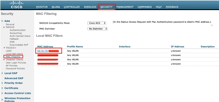
- Choose SECURITY >AAA >MAC Filtering > New .
- Enter the MAC address of the access point to the MAC Filter list; for example, 00:0B:91:21:3A:C7.
- Select a WLAN ID or Any WLAN from the Profile Name pop-up menu.
- Enter a description (32 characters maximum) of the access point in the Description field; for example, Fisher_Street_00.0B.91.21.3A.C7 shows the location and MAC address of the access point.
- Choose an interface from the Interface Name pop-up menu, and click Apply.
- Repeat Steps 2 to 6 to add other access points to the list.
- Save the controller configurations.
- Log out of your controller, and close your web browser.
DETAILED STEPS
| Step 1 |
Log into your controller using a web browser. |
||
| Step 2 |
Choose SECURITY >AAA >MAC Filtering > New . |
||
| Step 3 |
Enter the MAC address of the access point to the MAC Filter list; for example, 00:0B:91:21:3A:C7.
|
||
| Step 4 |
Select a WLAN ID or Any WLAN from the Profile Name pop-up menu. |
||
| Step 5 |
Enter a description (32 characters maximum) of the access point in the Description field; for example, Fisher_Street_00.0B.91.21.3A.C7 shows the location and MAC address of the access point. |
||
| Step 6 |
Choose an interface from the Interface Name pop-up menu, and click Apply. |
||
| Step 7 |
Repeat Steps 2 to 6 to add other access points to the list. |
||
| Step 8 |
Save the controller configurations. |
||
| Step 9 |
Log out of your controller, and close your web browser. |
Changing an Bridge AP Role
You can change the mode of an AP after it is registered with WLC. By default, all the bridge mode APs join the controller in mesh access point role. After the AP is registered in the WLC, the AP role can be changed to RAP or MAP form the WLC GUI or CLI.
Changing an Bridge AP Role From AireOS WLC
To change the AP role form GUI, follow these steps:
Procedure
| Step 1 |
Click Wireless. When your access point associates to the controller, the name of the access point appears in the AP Name list. |
| Step 2 |
Double-click your access point name. |
| Step 3 |
Go to the Mesh tab, and choose Root AP or Mesh AP by clicking the drop-down arrow in the AP Role field. You can also change the AP role from the controller CLI using the command: config ap role { rootAP | meshAP } Cisco_AP |
Changing an Bridge AP Role From IOS-XE WLC
To change the AP role form GUI, follow these steps:
Procedure
| Step 1 |
Go to Configuration > Access Points. |
| Step 2 |
Select the AP from the list to change its mode. |
| Step 3 |
Under General tab, change the mode of the AP to bridge. |
| Step 4 |
Go to the Mesh tab, change the role under General to Mesh or Root based on the requirement. You can also change the AP role from the controller CLI using the command: ap name ap-name role { mesh-ap | root-ap } |
Configuring a Root Access Point
The access point defaults to the mesh access point (MAP) radio role. One or more of your access points must be reconfigured as a root access point (RAP). The RAPs connect to a wired Ethernet link through a switch to the controller. The MAPs use their wireless backhaul interface to connect to a RAP to reach the controller.
To configure a RAP on the controller GUI, follow these steps:
Procedure
| Step 1 |
Log into your controller using a web browser. |
| Step 2 |
Click Wireless. When your access point associates to the controller, the name of the access point appears in the AP Name list. |
| Step 3 |
Double-click your access point name. |
| Step 4 |
Find Mesh Information, and choose Root AP by clicking the drop-down arrow in the AP Role field. |
| Step 5 |
Click Apply. |
| Step 6 |
Repeat Steps 2 through 5 for each RAP. |
| Step 7 |
Log out from your controller, and close your web browser. |
Configuring Mesh Access Points
Mesh networking employs Cisco Aironet outdoor mesh access points and indoor mesh access points along with Cisco Wireless Controller and Cisco Prime Infrastructure to provide scalability, central management, and mobility between indoor and outdoor deployments. Control and Provisioning of Wireless Access Points (CAPWAP) protocol manages the connection of mesh access points to the network.
The wireless mesh terminates on two points on the wired network. The first location is where the root access point (RAP) is attached to the wired network, and where all bridged traffic connects to the wired network. The second location is where the CAPWAP controller connect to the wired network; this location is where the WLAN client traffic from the mesh network is connected to the wired network. The WLAN client traffic from CAPWAP is tunneled to Layer 2. Matching WLANs should terminate on the same switch VLAN on which the wireless controllers are co-located. The security and network configuration for each of the WLANs on the mesh depend on the security capabilities of the network to which the wireless controller is connected.
For more information about designing and deploying mesh networks, see the relevant mesh deployment guides at:
For more information about configuring mesh access points running Cisco IOS-XE, see the "Mesh Access Points" chapter in relevant Cisco Catalyst 9800 Series Wireless Controller Software Configuration Guide at:
Mobility Express Support
The IW6300 and ESW6300 access points support AireOS Mobility Express Release 8.10.
For more information, see Cisco Mobility Express Deployment Guide and Cisco Wireless Mesh Access Points, Design and Deployment Guide at:
Uplink Selection
The IW6300 and ESW6300 access points support multiple uplink options: SFP, PoE-IN, and wireless.
For local mode and flexconnect mode, only POE-IN and SFP are uplink capable. For mesh mode, POE-IN, SFP, and radio slot 0/1 are uplink capable. The SFP port has higher priority than the PoE-IN interface. Uplink port can only be latched to PoE-IN or SFP interface when the AP boots up.
The uplink port will not change if only the POE-IN or SFP port is up when power cycle AP. But if the uplink port is added to the blacklist, or the interface is down, or the daisychain STP redundancy feature is enabled and a change is detected in the STP Root Port, and there are other interfaces that can be used as the uplink port, AP will switch the uplink port to the other interface. This is also applied to Mobility Express in Flexconnect mode or Flex+bridge mode.
Plugging and unplugging the SFP module will cause the AP to reboot. The SFP module monitor process is running after AP boots up. When it detects the SFP module is inserted or removed, it will make the AP to reboot. The PHY driver on SFP port will only be loaded by power recycle.
Connecting Data Cables
Both the Ethernet port and the SFP port cannot be used for uplink at the same time. If the SFP is detected and active, the Ethernet port is disconnected. If the SFP is not detected, the Ethernet port stays connected. If you are using the SFP port, to delivery data through a fiber-optic cable, then the AP needs to be powered by an external power source, or by a power injector.
The following sections describe uplink selection for different modes.
Uplink Selection for Local/Flex Mode
Use the following command on AP side to check the uplink port when AP joins the controller:
#show controllers nss status
CAPWAP Configuration:
|ID:34|TYPE:3|STATE:1|
|GATEWAY-MAC:00:59:DC:C2:08:81|AP-MAC:68:3B:78:98:63:A8|
|RADIO-BASE-MAC:DC:8C:37:35:C4:A0|PMTU:1485|
|WLC-IP:8.5.0.2|AP-IP:8.5.0.187|WLC-PORT:5247|AP-PORT:5248|
|DEST-PORT:1
|PROTO:0|TTL:250|FLBL:0|DTLS-ID:65535|
|VLAN-ID:0|OPT:0x0000000C|UQOSP:0|MQOSP:0|CSUM:1|
|L4RXBITS:  0|L4TXBITS:  0|L4HASHPROF:  0|
In the CLI output, “DEST-PORT:0” means the AP is using PoE-in port as capwap uplink port. “DEST-PORT:1” means the AP is using SFP port as capwap uplink port.
Uplink Selection for Bridge/Flex+Bridge Mode
When the PoE-IN interface is used as uplink port, the SFP interface should be kept unconnected. But for RAP Ethernet Daisy Chain, both POE-IN and SFP port should be connected.
If Root AP joined WLC on radio, when the wired interface become available, it will switch back to the wired interface. If Mesh AP joined WLC on radio, it will not try wired interface any more.
Use the following command on AP side to check the uplink for bridge or Flex+bridge mode:
#show mesh adj parent
AdjInfo: Wired Backhaul: 0
 [F4:DB:E6:6B:74:2C]
Mesh Wired Adjacency Info
Flags: Parent(P), Child(C), Reachable(R), CapwapUp(W), BlackListed(B) Authenticated(A)
Address           Cost RawCost BlistCount Flags: P C R W B A  Reject reason
F4:DB:E6:6B:74:2C 16   16      0            T/F: T F T T F T  -
------------------------------------------------------------------------------
In the CLI output, “Wired Backhaul: 0” means the AP is using PoE-in port as uplink port. “Wired Backhaul: 1” means the AP is using SFP port as uplink port.
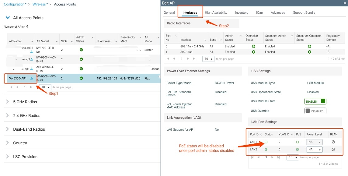
Configuring Ethernet LAN Ports
By default, the IW6300 and ESW6300 access point LAN port admin status is enabled. When you disable a LAN port, the PoE-OUT function of the LAN port will be turned off automatically. When you re-enable the LAN port, the PoE state will not be up until you turn on the PoE function manually.
When the LAN port is disabled, you cannot enable the LAN PoE function, which means you can only enable the PoE-OUT function of the LAN port when the port admin is in enabled state.
Supported AP mode:
-
Local
-
FlexConnect
-
Bridge
-
FlexBridge
Supported controller software release:
-
IOS XE 17.4.1 and later
The following table shows the mapping of LAN-Port-ID and PoE-OUT port between controller and AP:
|
LAN-Port-ID |
PoE-OUT Port |
|---|---|
|
1 |
PoE-OUT 1 |
|
2 |
PoE-OUT 2 |
LAN Port Status Configuration from CLI
To enable the AP LAN port admin from the controller, use the following command:
ap name <Cisco_AP_Name> lan port-id <LAN-Port-ID> enable
To disable the AP LAN port admin from the controller, use the following command:
ap name <Cisco_AP_Name> lan port-id <LAN-Port-ID> disable
To enable the PoE-OUT status after enabling the LAN port admin, use the following command:
ap name <Cisco_AP_Name> lan port-id <LAN-Port-ID> poe enable
To disable the PoE-OUT status after enabling the LAN port admin, use the following command:
ap name <Cisco_AP_Name> lan port-id <LAN-Port-ID> poe disable
LAN Port Status Configuration from GUI
To disable the LAN port admin from the controller GUI, choose the access point from Configuration -> Wireless -> Access Points . On the Interfaces tab, in the LAN Port Settings section, uncheck the Status checkbox of the LAN port. The PoE status of the LAN port will be disabled after the LAN port admin status is disabled.
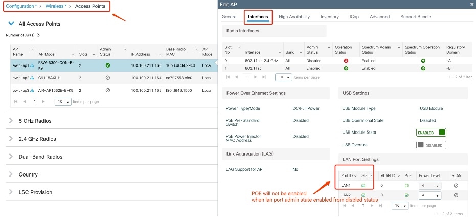
To enable LAN port admin from the controller GUI, choose the access point from Configuration -> Wireless -> Access Points . On the Interfaces tab, in the LAN Port Settings section, check the Status checkbox of the LAN port. The PoE status of the LAN port will not be enabled after the LAN port admin status is enabled.
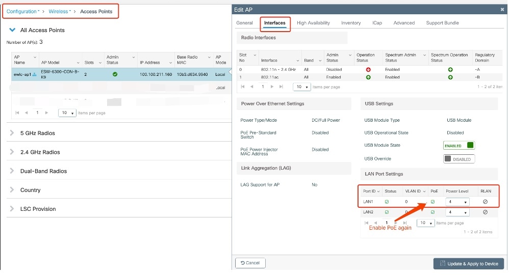
To enable the LAN port PoE status from the controller GUI, choose the access point from Configuration -> Wireless -> Access Points . On the Interfaces tab, in the LAN Port Settings section, check the PoE checkbox of the LAN port.
Checking LAN Port Status from Controller and AP
To check the LAN port status from the controller, use the show ap name <ap-name > lan port summary command.
eWLC#show ap name IW-6300-AP1 lan port summary
LAN Port status for AP IW-6300-AP1
Port ID      status       vlanId      poe         power-level   RLAN
----------------------------------------------------------------------
LAN1         Disabled     0           Disabled    NA            Disabled
LAN2         Enabled      0           Enabled     NA            Disabled
eWLC#show ap name IW-6300-AP1 lan port summary
LAN Port status for AP IW-6300-AP1
Port ID      status       vlanId      poe         power-level   RLAN
----------------------------------------------------------------------
LAN1         Enabled      0           Disabled    NA            Disabled
LAN2         Enabled      0           Enabled     NA            Disabled
eWLC#show ap name IW-6300-AP1 lan port summary
LAN Port status for AP IW-6300-AP1
Port ID      status       vlanId      poe         power-level   RLAN
----------------------------------------------------------------------
LAN1         Enabled      0           Enabled     4             Disabled
LAN2         Enabled      0           Enabled     NA            Disabled
To check the LAN port status from the AP, use the show configuration rlan command.
IW-6300-AP1#show configuration rlan
RLAN Configuration:
----------------------------------
 RLAN interface config:   _lan_port_num = 2
   _num_of_wan_ports = 2
   ap_admin_state: 1 (1-ENABLED, 2-_DISABLED)
   _intf_cfg.adminState: 1 (1-ENABLED, 2-_DISABLED)
   _intf_cfg.configState: 2 (1-DOWN, 2- UP)
   _intf_cfg.operationalState : 2 (1-DOWN, 2-UP)
   Override: 0
   LanFastSwitching: Disabled
   Base_MAC: DC:8C:37:35:AF:20
========= end of config ==========
----------------------------------
    PORT[1] <----PoE Out 1
       port_admin_state: 1 <----check port admin status
       rlanId: 0
       poeEnable: 1 <----check port PoE status
       lan_port_enabled: 0
       client_count: 0
      client_mac: 00:00:00:00:00:00
----------------------------------
    PORT[2] <----PoE Out 2
       port_admin_state: 1
       rlanId: 0
       poeEnable: 1
       lan_port_enabled: 0
       client_count: 0
      client_mac: 00:00:00:00:00:00
----------------------------------
    PORT[3]
       port_admin_state: 0
       rlanId: 0
       poeEnable: 0
       lan_port_enabled: 0
       client_count: 0
      client_mac: 00:00:00:00:00:00
----------------------------------
    PORT[4]
       port_admin_state: 0
       rlanId: 0
       poeEnable: 0
       lan_port_enabled: 0
       client_count: 0
      client_mac: 00:00:00:00:00:00
========= end of stats ==========
Configuring PoE Out Function
The IW6300 and ESW6300 access points support PoE output functionality. There are two Ethernet LAN ports capable of supplying PoE power. The total available PoE power is 35.3W when the input power source is DC, DCW, or AC. The PoE output will be disabled when PoE (IEEE 802.3at, UPoE) or power injector is the power source.
By default, the PoE out function is enabled. You can enable or disable PoE out function per AP group or per AP by CLI options. During the AP reboot procedure, power manager reads local PoE configuration file to turn on or turn off power, so that AP can provide power before joining WLC.
Note |
CDP/LLDP is not supported on PoE out ports. APs supply power based on hardware classification and power level configuration. |
The following table shows the mapping between power level and power capacity.
|
Power Level |
Max PoE Class |
Max Power from PSE |
Usage |
|---|---|---|---|
|
None |
4 |
30W |
Default |
|
1 |
1 |
4W |
Optional |
|
2 |
2 |
7W |
Optional |
|
3 |
0/3 |
15.4W |
Optional |
|
4 |
4 |
30W |
Optional |
The following table shows the definition for class of PoE.
|
Class |
Maximum power delivered by PSE |
|---|---|
|
0 (class status unknown) |
15.4W |
|
1 |
4W |
|
2 |
7W |
|
3 |
15.4W |
|
4 |
30 W (For IEEE 802.3at Type 2 powered devices) |
The following table shows the access point POE out port power allocation. Power manager holds 35.3 Watts when power source is AC, DC, or DCW.
|
PoE Port 1 |
PoE Port 2 |
|
|---|---|---|
|
PSE: 35.3W (including 4.5W USB) |
Disconnected |
Class 0/1/2/3/4 |
|
Class 1 |
Class 0/1/2/3/4 |
|
|
Class 2 |
Class 0/1/2/3 |
|
|
Class 0/3 |
Class 0/1/2/3 |
|
|
Class 4 |
Class 1 |
|
|
Class 0/1/2/3/4 |
Disconnected |
Note |
USB interface will share the power with PoE-out port with AC or DC power source. When USB is disabled, PSE can use the USB port power (4.5W). For more information, see USB Support. |
Note |
PoE Out is not supported on WGB mode. |
Note |
For DC SKU, if you want to output 802.3at type 2 PoE out power, DC input must >=51V. If you want to output 802.3af (802.3at type 1) PoE out power, DC input must >=45V. |
Configuration From AireOS WLC CLI
Use the following commands to configure the PSE function:
Global (AP Group Scope)
(Cisco Controller) >config wlan apgroup port lan [1|2] iw6300-1 [enable|disable]
(Cisco Controller) >config wlan apgroup port lan [1|2] iw6300-1 poe [enable|disable]
(Cisco Controller) >config wlan apgroup port lan [1|2] iw6300-1 power-level [1|2|3|4]
(Cisco Controller) >config ap group-name iw6300-1 AP6CB.D383.B404
Override (AP Specific Scope)
(Cisco Controller) >config ap lan over-ride [enable|disable] AP6C8B.D383.B404
(Cisco Controller) >config ap lan port-id [1|2] [enable|disable] AP6C8B.D383.B404
(Cisco Controller) >config ap lan port-id [1|2] poe [enable|disable] AP6C8B.D383.B404
(Cisco Controller) >config ap lan port-id [1|2] power-level [1|2|3|4] AP6C8B.D383.B404
Use the following commands to check the status:
From WLC
(Cisco Controller) >show wlan apgroups
Total Number of AP Groups........................ 1
Site Name........................................ default-group
Site Description................................. <none>
Lan Port configs
----------------

LAN Status POE Power Level RLAN
--- ------- ---- ---------- -----
1 Disabled Disabled None None
2 Disabled Disabled None None
3 Disabled None
4 Disabled Disabled None

(Cisco Controller) >show ap lan 1 <AP-Name>
LAN Port configuration for AP <AP-Name>
Lan Override .................................... Enabled
 Port    Status        PoE               Power-Level
------  --------    ---------            ----------------
 LAN1   DISABLED     DISABLED            1

(Cisco Controller)>show ap lan port-summary AP6C8B.D383.B404
LAN Port configuration for AP AP6C8B.D383.B404
Lan Override .................................... Enabled
Port Status POE Power Level
------ -------- -------- ----------------
LAN1 ENABLED ENABLED 3
LAN2 ENABLED ENABLED 2
From AP
ap >show power status
Device ID: 0xc4, Firmware Reversion:0x40, Bus:3, Address:0x24
Operating Mode: Semiauto
Available: 35.3(w)    Used:15.4(w)    Remaining:19.9(w)
Interface    Admin    Oper    Power    Class Max   Config Power
---------    -----    ----    -----    ---------   ------------
POE-out 1    Up       ON      8.1      30.0        15.4
POE-out 2    Up       OFF     0.0      0.0         30.0
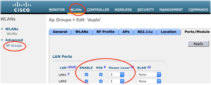
Configuration From AireOS WLC GUI
Global (AP group)
WLANs -> Advanced -> AP Groups -> specific AP group -> Ports/Module -> LAN Ports
Add AP to ap group
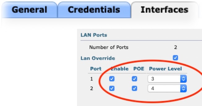
AP Override
Wireless -> Access Points -> specific AP -> Interfaces -> LAN Override/PoE/Power Level
Configuration From IOS-XE WLC CLI
Global (AP Group Scope)
#ap name APbadb.ade7.dd1e lan port-id 1 enable
#ap name APbadb.ade7.dd1e lan port-id 2 enable
(config)#ap remote-lan profile-name duplo_pse_profile 1
(config-remote-lan)#no shut
(config-remote-lan)#end
(config)#ap remote-lan-policy policy-name duplo_pse_policy
(config-remote-lan-policy)#poe
(config-remote-lan-policy)#power-level [1|2|3|4]
(config-remote-lan-policy)#no shut
(config-remote-lan-policy)#end
(config)#wireless tag policy duplo_pse_tag
(config-policy-tag)#remote-lan duplo_pse_profile policy duplo_pse_policy port-id 1
(config)#ap APbadb.ade7.dd1e
(config-ap-tag)#policy-tag duplo_pse_tag
Override (AP Specific Scope)
ap name APBADB.ADE7.DD1E lan port-id [1|2] [enable|disable]
ap name APBADB.ADE7.DD1E lan port-id [1|2] poe [enable|disable]
ap name APBADB.ADE7.DD1E lan port-id [1|2] power-level [1|2|3|4]
Use the following command to check the status:
eWLC#show ap name APBADB.ADE7.DD1E lan port summary
LAN Port status for AP APBADB.ADE7.DD1E
Port ID status vlanId poe power-level RLAN
----------------------------------------------------------------------
LAN1 Enabled 0 Enabled 3 Disabled
LAN2 Enabled 0 Enabled 2 Disabled
Configuration From IOS-XE WLC GUI
To configure PSE function, go to Configuration >Wireless >Access Points >specific AP >interfaces >LAN Port Settings , then select the following:
-
Status: Port admin status (enable/disable)
-
PoE: PoE function status (enable/disable)
-
Power Level: level 1 - 4 (4w, 7w, 15.4w, 30w)
USB Support
The IW6300 and ESW6300 access points are equipped with one external type A USB 3.0 host port. It is backward compatible with USB 2.0, and capable of supplying a maximum of 4.5W (900mA, 5V) output.
Note |
The USB configuration on ESW6300 is officially supported from Cisco IOS-XE Release 17.1.1t. The USB configuration on IW-6300H is officially supported from Cisco IOS-XE Release 17.4.1 and 17.3.3, and AireOS Release 8.10.151.0. |
USB Overview
By default, the USB configuration is set to ENABLED, which means a brand new ESW6300 or IW-6300H turns on USB port by default, and an ESW6300 or IW-6300H that has been performed factory reset turns on USB port by default.
The USB port can supply power output only when the USB port is enabled and the power source is AC/DC/UPoE and 60W power injector. If the power budget is not enough to power on the connected device, an error message "Not enough power resource" will be displayed.
Note |
When the power injector (for example, AIR-PWRINJ-60RGD) is connected as power source, it takes about 90 seconds to turn on the USB device, as the access point need to wait for timeout of CDP negotiation. |
Managing the USB Port
This section describes the configurations on AireOS WLC and IOS-XE to manage the USB port.
Configuration on AireOS WLC
-
To enable or disable the USB port on all APs belonging to a specific AP group, use the following command:
config wlan apgroup port usb-module ap-group-name {enable|disable}You can also configure the USB port from AireOS GUI: WLANs→ Advanced → AP Groups → specific AP group → Ports/Module → USB Module, add AP to AP group
To verify the configuration use the following command:
(Cisco Controller) >show wlan apgroups [snip] USB Module configs ----------------------------- USB Module Status................................ Enabled -
To enable or disable the USB port, overriding the AP group setting:
config ap usb-module over-ride {enable|disable} ap-nameWhen the overriding command is enabled, to enable or disable the USB port on a specific AP, use the following command:
config ap usb-module {enable|disable} ap-nameYou can also configure the USB port from GUI: Wireless → Access Points → specific AP → Advanced → Override / USB Module Status
To verify the configuration use the following command:
(Cisco Controller) >show ap config general AP6C8B.D383.B404
External Module:
USB Module Type.................................. USB Module
USB Module Status................................ Disabled
USB Module Operational State..................... Not Detected
Configuration on IOS-XE
-
To apply default AP profile to AP and enable or disable the USB port, use the following commands:
eWLC(config)#ap profile default-ap-profile eWLC(config-ap-profile)#[no] usb-enable -
To enable or disable the USB port, overriding the AP group setting:
eWLC#ap name ap-name [no] usb-module override eWLC#ap name ap-name [no] usb-module -
To verify the configuration use the following command:
eWLC#show ap name APBADB.ADE7.DD1E config general | inc USB
USB Module Type : USB Module
USB Module State : Enabled
USB Operational State : Disabled
USB Override : Enabled
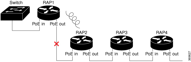
RAP Ethernet Daisy Chain
In a daisy chain topology as shown in the following figure, if the link between RAP1 and RAP2 is broken, or RAP1 loses CAPWAP connectivity to the controller or switch, RAP2 will change its backhaul to wireless link. The Ethernet interfaces of RAP2 will be blocked and no child mesh AP will be allowed. Then, RAP3 and RAP4 will lose connection if they are far away from RAP1.
For the access point joining over wireless backhaul, it stays on wireless backhaul for 15 minutes and comes back to scan state every 15 minutes, until it finds a wired backhaul and joins the controller.
The RAP Ethernet Daisy Chain feature enhances the existing Ethernet bridging functionality by introducing a new command to configure strict wired uplink on each access point. It forces the bridge AP to stick to the Ethernet link, and block the selecting of wireless link for uplink backhaul. Even the Ethernet link failure happens, the access point will never select a parent over wireless backhaul.
The following figure shows an example of RAP Ethernet Daisy Chain topology. Standalone power source (AC, DC, or power injector) is provided to each RAP.
When strict-wired-uplink is enabled, if RAP1 loses CAPWAP connection or the mesh function is broken, but the physical link between RAP1 and the switch is still connected, all RAPs behind RAP1 in the chain will not lose uplink and CAPWAP connection. Traffic can be forwarded as usual. However, all the remaining RAPs in the chain will lose CAPWAP connection if the physical link between RAP1 and the switch is broken, or RAP1 is restarted.
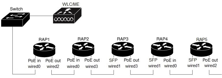
Configuration Guidelines
The following table shows the port mapping between panel lable and software configuration CLI.
|
Panel Label |
SW Interface |
|---|---|
|
POE IN |
wired 0 |
|
SFP |
wired 1 |
|
POE OUT 1 |
wired 2 |
|
POE OUT 2 |
wired 3 |
Follow these guidelines when you configure this feature:
-
All APs in daisy chain should be operating in Bridge or Flex+Bridge mode with Root AP role.
-
PoE-IN (wired0) and SFP (wired1) port can be used as uplink port, but PoE-OUT (wired2 and wired3) cannot be used as uplink port. PoE-IN (wired0) port and PoE-OUT(wired2 and wired3) ports can be used as downlink port.
-
SFP (wired1) port cannot be used as downlink. When PoE-IN (wired0) is used as uplink, SFP (wired1) port should be disconnected. When SFP (wired1) port is used as uplink, you can use GLC-T to connect to other AP’s Ethernet port.
-
Ethernet bridging on all RAPs in the chain should be enabled and secondary Ethernet interfaces needs to be configured according to the mesh deployment guidelines.
-
VLAN transparency should be disabled on all daisy-chained RAPs.
-
The RAPs in Ethernet Daisy Chain can accept MAP association and wireless client association.
-
Strict wired uplink must be enabled to prevent RAP in daisy chain from switching to wireless backhaul when the wired uplink path fails, so that the RAP can recover quickly when the uplink wired path is recovered.
-
All the traffic will go through RAP1 which is a bottleneck and the total network throughput is limited. There should be around 10% bandwidth reserved for CAPWAP management traffic in high traffic load case.
Note |
After the configuration, the AP may be in MAP role. It is required to prime all AP to RAP role before connecting all of them with the wired connection. Otherwise there may be loop issues if MAP uses wireless backhaul to connect to the other AP. |
The following are two deployment options.
Option 1
SUMMARY STEPS
- Connect the mesh AP to WLC through wired connection.
- Prime all APs to RAP role on the daisy chain topology.
- Configure config ap bridging enable <Cisco_AP > to enable Ethernet bridging. This command allows the next AP to connect on its Secondary Ethernet interface.
- Configure config ap strict-wired-uplink enable <Cisco_AP > to enable the feature. At this time, the AP can only connect to WLC through a wired connection.
- Connect all APs using wired RAP daisy chain topology.
DETAILED STEPS
| Step 1 |
Connect the mesh AP to WLC through wired connection. |
| Step 2 |
Prime all APs to RAP role on the daisy chain topology. |
| Step 3 |
Configure config ap bridging enable <Cisco_AP > to enable Ethernet bridging. This command allows the next AP to connect on its Secondary Ethernet interface. |
| Step 4 |
Configure config ap strict-wired-uplink enable <Cisco_AP > to enable the feature. At this time, the AP can only connect to WLC through a wired connection. |
| Step 5 |
Connect all APs using wired RAP daisy chain topology. |
Option 2
SUMMARY STEPS
- Connect all the APs using wired RAP daisy chain topology. Make sure all APs are powered off.
- Power on the first AP which is closest to the switch or WLC. Make sure it can connect to WLC through a wired connection.
- Set the AP role to RAP.
- Configure config ap bridging enable <Cisco_AP > to enable Ethernet bridging. This command allows the next AP to connect on its Secondary Ethernet interface.
- Configure config ap strict-wired-uplink enable <Cisco_AP > to enable the feature. At this time, the AP can only connect to WLC through a wired connection.
- Power on the AP which is next to the previous AP.
- Repeat Step3 to Step 5.
DETAILED STEPS
| Step 1 |
Connect all the APs using wired RAP daisy chain topology. Make sure all APs are powered off. |
| Step 2 |
Power on the first AP which is closest to the switch or WLC. Make sure it can connect to WLC through a wired connection. |
| Step 3 |
Set the AP role to RAP. |
| Step 4 |
Configure config ap bridging enable <Cisco_AP > to enable Ethernet bridging. This command allows the next AP to connect on its Secondary Ethernet interface. |
| Step 5 |
Configure config ap strict-wired-uplink enable <Cisco_AP > to enable the feature. At this time, the AP can only connect to WLC through a wired connection. |
| Step 6 |
Power on the AP which is next to the previous AP. |
| Step 7 |
Repeat Step3 to Step 5. |
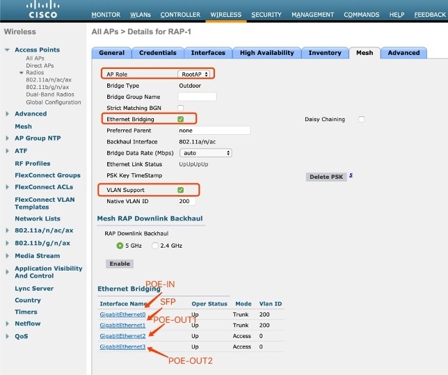
Mesh Configuration From AireOS WLC or ME Controller
Follow these steps to configure from WLC or ME controller:
SUMMARY STEPS
- Configure AP to bridge or Flex+Bridge mode if AireOS WLC is used. For ME controller, only Flex+Bridge mode is supported.
- Configure AP role to rootAP.
- Enable Ethernet bridging.
- Configure access mode or trunk mode for the RAP Ethernet secondary port PoE-OUT1 and PoE-OUT2. POE-IN port also can be used as secondary port if SFP port acts as uplink port.
DETAILED STEPS
| Step 1 |
Configure AP to bridge or Flex+Bridge mode if AireOS WLC is used. For ME controller, only Flex+Bridge mode is supported. Example: |
| Step 2 |
Configure AP role to rootAP. Example: |
| Step 3 |
Enable Ethernet bridging. Example: |
| Step 4 |
Configure access mode or trunk mode for the RAP Ethernet secondary port PoE-OUT1 and PoE-OUT2. POE-IN port also can be used as secondary port if SFP port acts as uplink port. |
Configuring Strict Wired Uplink
Use the following command to enabled or disable strict wired uplink on a specific AP. Mesh function will restart after this configuration.
(Cisco Controller) > config ap strict-wired-uplink {enable|disable} <Cisco_AP>
enable Enables Strict Wired Uplink on the Cisco AP.
disable Disables Strict Wired Uplink on the Cisco AP.
Verifying the Configuration
Use the following command to check the status of strict-wired-uplink:
(WLC) >show ap config general <Cisco_AP>
AP Mode ......................................... Bridge
AP Role ......................................... RootAP
Ethernet Bridging ............................... Enabled
Strict Wired Uplink ............................. Enabled
AP Vlan Trunking ................................ Enabled
AP Native Vlan ID: .............................. 120
Use the following command to display the feature status for all bridge RAP:
(WLC) >show mesh strict-wired-uplink summary
AP Name AP Model BVI MAC Role Bridge Group Name Strict Wired Uplink
------------------ ------------------- ----------------- ---- ----------------- --------------------
duplo-ap2 ESW-6300-CON-B-K9 6c:8b:d3:83:b4:04 RAP default Disable
duplo-ap1 ESW-6300-CON-B-K9 6c:8b:d3:83:b4:68 RAP default Enable
Number of Mesh RAP Strict Wired Uplink Set....... 1
Use the following command to check RAP Ethernet status:
(WLC) >show mesh env summary
AP Name Temperature(C/F) TempState Heater Battery Orientation Ethernet
------------------ ---------------- --------- ------ ------- ----------- --------
duplo-ap1 50/122 GREEN OFF N/A N/A UpUpUpUp <--(Note: interface order: wired0, wired1, wired2, wired3)
duplo-ap2 72/161 GREEN OFF N/A N/A UpUpUpDn
Use the following command to check Ethernet interface Vlan configuration:
(WLC) >show ap config ethernet summary
Vlan Tagging Information For AP duplo-ap1
Ethernet 0
Mode: ACCESS
Access Vlan 0
Ethernet 1
Mode: ACCESS
Access Vlan 0
Ethernet 2
Mode: TRUNK
Native Vlan 120
Allowed Vlans:
Ethernet 3
Mode: ACCESS
Access Vlan 0
Use the following AP commands to check RAP status on the AP:
duplo-ap1#show mesh config
AP Specific Configuration:
AP Role: Root AP
Backhaul Mode: 802.11a
Internal DHCP Running Status: Disabled
Strict Wired Uplink: Enabled
Ethernet Bridging: Enabled
duplo-ap1#show mesh forwarding all
Vlan config
Static Secondary Ethernet VLAN Configuration :
Active Ethernet Interface: wired2
Port Secondary Mode: TRUNK
Port Secondary Native Vlan: 120
Allowed Vlan:
Static Transparent Mode For All Secondary Ethernet Ports: Disabled
Static Ap Native Vlan: 120
Running Ap Native Vlan: 120
Running Secondary Ethernet VLAN Configuration :
Active Ethernet Interface: wired2
Port Mode: TRUNK
Port Native Vlan: 120
Allowed Vlan:
Running Transparent Mode : Disabled
duplo-ap1#show mesh backhaul
Wired Backhaul: 0 [6C:8B:D3:83:B4:68] <-------------POE-IN Port
idx Cost Uplink InterfaceType
0 Invalid FALSE WIRED
Mesh Wired Adjacency Info
Flags: Parent(P), Child(C), Reachable(R), CapwapUp(W), BlackListed(B) Authenticated(A)
Address Cost RawCost BlistCount Flags: P C R W B A Reject reason
6C:8B:D3:83:B4:68 16 16 0 T/F: F F F F F F Filtered
----------------------------------------------------------------
Wired Backhaul: 1 [6C:8B:D3:83:B4:68] <-------------SFP Port
idx Cost Uplink InterfaceType
1 16 TRUE WIRED
Mesh Wired Adjacency Info
Flags: Parent(P), Child(C), Reachable(R), CapwapUp(W), BlackListed(B) Authenticated(A)
Address Cost RawCost BlistCount Flags: P C R W B A Reject reason
6C:8B:D3:83:B4:68 16 16 0 T/F: T F T T F T -
----------------------------------------------------------------
Radio Backhaul: 0 [6C:8B:D3:D5:31:31]
idx State Role RadioState Cost Uplink Downlink Access ShutDown ChildrenAllowed InterfaceType
2 INITIAL ACCESS UP Invalid FALSE FALSE TRUE FALSE FALSE RADIO
No Radio Adjacency Exists
------------------------------------------------------------------------------
Radio Backhaul: 1 [6C:8B:D3:D5:31:31]
idx State Role RadioState Cost Uplink Downlink Access ShutDown ChildrenAllowed InterfaceType
3 MAINT DOWNLINK UP Invalid FALSE TRUE FALSE FALSE TRUE RADIO
No Radio Adjacency Exists
------------------------------------------------------------------------------
Mesh Configuration From IOS-XE WLC Controller
Configure access mode or trunk mode for the RAP ethernet secondary port PoE-OUT1 and PoE-OUT2.
-
Access mode configuration
#ap name a mesh ethernet 2 mode access <Vlan-ID>
-
Trunk mode configuration, vlan support must be enabled in advance and disable vlan transparent
#ap name <Cisco AP> mesh vlan-trunking #ap name <Cisco AP> mesh vlan-trunking native <Vlan-ID> #ap name <Cisco AP> mesh ethernet 2/3 mode trunk vlan native <Vlan-ID> #ap name <Cisco AP> mesh ethernet 2/3 mode trunk allowed <Vlan-ID>
-
The configuration of ssid-broadcast-persist has the same function with strict wired uplink in AireOS controller. To enable ssid-broadcast-persist:
#configure terminal (config)#ap profile rap-ssid-join-profile (config-ap-profile)#ssid broadcast persistent Enabling persistent SSID broadcast will cause associated APs to rejoin. Are you sure you want to continue? (y/n)[y]: y (config-ap-profile)#end #show ap profile name rap-ssid-join-profile detailed | in SSID Persistent SSID Broadcast : ENABLED
-
To disable ssid-broadcast-persist:
#config terminal (config)#ap profile rap-ssid-join-profile (config-ap-profile)#no ssid broadcast persistent Disabling persistent SSID broadcast will cause associated APs to rejoin. Are you sure you want to continue? (y/n)[y]: y (config-ap-profile)#end #show ap profile name rap-ssid-join-profile detailed | in SSID Persistent SSID Broadcast : DISABLED
Checking ssid-broadcast-persist Status From IOS-XE WLC Controller
Note |
Configuring and showing status of ssid-broadcast-persist are only supported by CLI, and not supported on GUI. |
-
Use the following command to check if ssid-broadcast-profile is enabled or disabled:
#show ap profile name ssid-ap-profile detailed Persistent SSID Broadcast : ENABLEDDHCP server : DISABLED ----------------------------------------------------------- Persistent SSID Broadcast : DISABLEDDHCP server : DISABLED
-
Use the following command to associate AP profile to a site tag and then to a specific AP:
#config terminal (config)#wireless tag site ssid-policy-tag (config-site-tag)#ap-profile rap-ssid-join-profile Changing ap profile mapping may result in the rejoin of AP's associated to the Site tag (config-site-tag)#end #config terminal (config)#ap 6c8b.d383.b468 (config-ap-tag)#site-tag rap-ssid-site-tag Associating site-tag will cause associated AP to reconnect (config-ap-tag)#end
RAP Ethernet Daisy Chain Redundancy for STP Ring Topology
In the mesh Ethernet daisy chain deployment where the daisy chain is extended to a long range to connect a series of root access points (RAPs) via Ethernet ports, if there is a failure in the middle of the daisy chain, either a RAP node failure or a cabling failure, the traffic will be lost from the failure point throughout to the end of the daisy chain. This section describes the redundant RAP Ethernet daisy chain with STP ring topology, which is supported from AireOS Release 8.10 MR2.
Note |
This feature is supported on IOS-XE WLC controller from Release 17.3.1. For detailed information about configuration on IOS-XE controller, see https://www.cisco.com/c/en/us/td/docs/wireless/controller/9800/17-9/config-guide/b_wl_17_9_cg/m-redundant-rap.html. |
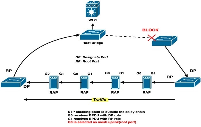
As shown in the following figure, the IW6300H access point has four Ethernet GE ports, but only G0 and G1 can be used as uplink backhaul and will be used to form the ring topology.
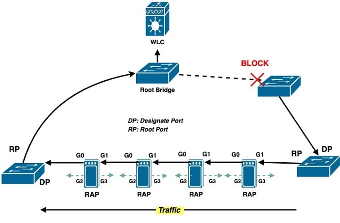
When the STP redundancy feature is disabled, the default RAP root port will be set to G1. When the RAP STP redundancy is enabled, if the ring breaks somewhere inside or outside of the daisy chain, the traffic will flow via both ends of the chain. Ring Topology Case Analysisshows the cases where ring breaks in different locations of the daisy chain.
When the RAP STP redundancy is enabled, the mesh RAPs will transparently relay STP BPDUs between G0 and G1, snoop the STP BPDUs and determine which WAN port (G0 or G1) will be the active port as backhaul uplink, and switch to new Ethernet backhaul uplink if root port change is detected from STP snooping. The port which receives BPDU with DP role will be the mesh root port (uplink) for the RAP.
Configuration Guidelines
-
Bridge mode and Flex+Bridge mode access points are supported.
-
Ethernet bridging and strict-wired-uplink should be enabled on the AP.
-
Both ends of the Ethernet daisy chain must be within the STP ring topology.
-
STP traffic is only relayed and snooped in the daisy chain RAPs while the switches in the ring take STP actions (for example, port blocking).
-
Only POE-IN (wired0) and SFP (wired1) port can be used as STP upstream/downstream port. (For the port mapping between panel label and CLI configuration, see the Port Mapping table in Configuration Guidelines.)
-
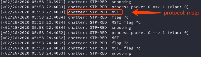
Supported STP protocols: IEEE 802.1w RSTP, Cisco RPVST+, and IEEE 802.1s MSTP.
-
When RPVST+ is used, there will be per-VLAN STP instance. The snooping will happen on native VLAN (that is, the VLAN which carries CAPWAP traffic).
-
When MSTP is used, it is required that only ONE MST instance exists alongside the daisy chain.
-
Only AC, DC, and power injector power supply can be used in RAPs.
-
It is recommended that you connect each RAP’s G0 port with neighbor RAP’s G1 port in the daisy chain using GLT-C. (When this feature is disabled, RAP will always use G1 (SFP) port to join WLC. Such kind of connection will align all RAPs to join WLC.)
Ring Topology Case Analysis
-
Ring broken/blocking outside of the daisy chain.
-
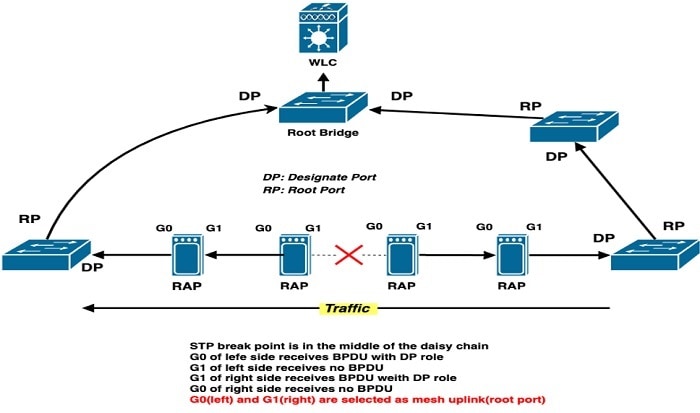
Ring broken inside the daisy chain.
-
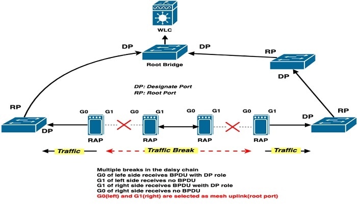
Multiple broken points inside the daisy chain.
STP Configuration on Switch
Sample configuration for Cisco RPVST+
-
Create VLANs on the switch. In the following example, vlan 200 is native vlan and carry out capwap traffic, vlan 201 and 202 are vlans for data traffic.
ring-sw2#show vlan brief VLAN Name Status Ports ---- ------------------ ------- ---------------------- 1 default active Gi0/2, Gi0/3, Gi0/6 200 VLAN0200 active 201 VLAN0201 active 202 VLAN0202 active -
Configure the port which is connected to the access point SFP port.
interface GigabitEthernet0/4 description *to-duplo-p2-1-sfp* switchport trunk allowed vlan 200-202 switchport trunk native vlan 200 load-interval 30 -
Configure STP.
spanning-tree mode rapid-pvst spanning-tree extend system-id spanning-tree vlan 200 priority 24576 spanning-tree vlan 201-202 priority 28672
Sample configuration for IEEE MSTP
spanning-tree mode mst
spanning-tree extend system-id
!
spanning-tree mst configuration
name rap-stp-red-test
revision 1
instance 1 vlan 200-202
You can use the following show commands to check the STP configuration:
show spanning-tree [summary|detail|root]
show spannng-tree [interface|vlan]
show spanning-tree mstMesh Configuration for AireOS/ME Controller
To enable or disable the Ethernet redundancy feature, use the following command:
config ap daisychain-stp-redundancy {enable|disable} <Cisco AP>To display the status of the Ethernet daisy chain redundancy status, use the following show commands:
show ap config ethernet summary
show mesh ethernet daisy-chain stp-redundancy summary
show mesh ethernet daisy-chain status all
To display the AP status in the chain, use the following command:
(WLC) >show mesh ethernet daisy-chain status [bridgegroupname|all]The RAP STP redundancy is based on Ethernet bridging and strict wired uplink function. The following configuration should be enabled in advance.
-
Add AP Ethernet MAC address into controller.
(WLC) > config macfilter add <Mac Addr> 0 -
Configure AP to bridge or FlexBridge mode if AireOS controller is used. ME controller only supports FlexBridge after AP has already been registered to controller.
(WLC) > config ap mode bridge <Cisco AP> (WLC) > config ap mode flex+bridge submode none <Cisco AP> -
Configure AP role to root AP.
(WLC) > config ap role rootAP <Cisco AP> -
Enable the Ethernet bridging function.
(WLC) > config ap bridging enable <Cisco AP> -
Enable strict-wired-uplink
(WLC) > config ap strict-wired-uplink enable <Cisco AP> -
Enable daisychain-stp-redundancy
(WLC) > config ap daisychain-stp-redundancy enable <Cisco AP>
RAP STP Redundancy VLAN Configurations
Trunk mode is recommended for POE-IN and SFP ports which should be configured first.
-
Global mesh trunk configuration
(WLC) > config mesh ethernet-bridging vlan-transparent disable (WLC) > config ap vlan-trunking enable <Cisco AP> (WLC) > config ap vlan-trunking native <Vlan-ID> <Cisco AP> -
Trunk config for stp redundancy uplink ports (wired0<-->POE-IN; wired1<-->SFP)
(WLC) > config ap ethernet [0|1] mode trunk enable <Cisco AP> native-vlan <Vlan-ID>
(WLC) > config ap ethernet [0|1] mode trunk add <Cisco AP> <Vlan-ID>
For RAP Ethernet secondary port POE OUT1 and POE OUT2, either access mode or trunk mode can be configured based on your requirement.
-
Access mode configuration
(WLC) > config ap ethernet [2|3] mode access enable <AP name> -
Trunk mode configuration. Vlan support must be enabled in advance and vlan transparent should be disabled.
(WLC) >config ap ethernet [2|3] mode trunk enable <Cisco AP> native-vlan <Vlan-ID>
(WLC) >config ap ethernet [2|3] mode trunk add <Cisco AP> <Vlan-ID>
Check Status from AireOS/ME controller
Use the following command to check if the access point Ethernet MAC address is added successfully:
(WLC) >show macfilter summary

MAC Filter RADIUS Compatibility mode............. Cisco ACS
MAC Filter Delimiter............................. None
MAC Filter Entries............................... 1

Local Mac Filter Table

MAC Address               WLAN Id          IP Addr           Description
-----------------------   --------------   ---------------   ------------
68:3b:78:xx:xx:xx         Any              unknown
Use the following commands to check the RAP stp-redundancy status:
-
From the mesh side:
(WLC) >show mesh ethernet daisy-chain stp-redundancy summary AP Name AP Model BVI MAC Role Bridge Group Name STP Redundancy State ------------- ------------------ ----------------- ---- ----------------- -------------------- RAP-2 IW-6300H-DC-B-K9 6c:8b:d3:xx:xx:xx RAP default Enable RAP-1 IW-6300H-AC-B-K9 68:3b:78:xx:xx:xx RAP default Disable Number of Mesh RAP Stp-Redundancy Set............ 1 -
From the AP side:
(WLC) >show ap config general RAP-1
…
AP Mode ......................................... Bridge
AP Role ......................................... RootAP
Ethernet Bridging ............................... Enabled
Strict Wired Uplink ............................. Enabled
Daisychain Stp Redundancy ....................... Enabled
AP Vlan Trunking ................................ Enabled
…
Use the following command to check the Ethernet interface VLAN configuration:
(WLC) >show ap config ethernet RAP-1
Vlan Tagging Information For AP RAP-1
  Ethernet 0      <<< POE IN port
    Mode: TRUNK
      Native Vlan 200
      Allowed Vlans: 201 202
  Ethernet 1      <<< SFP port
    Mode: TRUNK
      Native Vlan 200
      Allowed Vlans: 201 202
  Ethernet 2      <<< POE OUT1 port
    Mode: ACCESS
      Access Vlan 0
  Ethernet 3      <<< POE OUT2 port
    Mode: ACCESS
      Access Vlan 0
Use the following command to check the interface status:
(Ring-WLC-3504) >show mesh ethernet daisy-chain status all

AP Name          BVI MAC           Bridge Group Name     Backhaul    Ethernet      STP Red
----------   -----------------    -----------------    ----------   --------      -------
RAP-1        68:3b:78:xx:xx:xx      default             Ethernet0    UpUpUpUp     Enable
RAP-2        6c:8b:d3:xx:xx:xx      default             Ethernet0    UpUpUpDn     Enable

Number of Ethernet daisy chain RAP............... 2
In above output, the Ethernet status UpUpUpUp/UpUpUpDn refers to POE IN, SFP, POE OUT1, and POE OUT2 port.
Note |
Configuring and showing status of strict-wired-uplink and stp-redundancy are only supported by CLI, and not supported on GUI. |
Check Daisy chain AP topology and Backhaul on WLC.
It is recommended that AP name in topology is configure in alphabetical order, so that the following CLI output result will reflect the actual AP topology, and the current backhaul interface is also displayed,
|----(wired0) Duplo_01(wired1) --------(wired0) Duplo_02(wired1)-------(wired0)Duplo_03(wired1)---|
|-----------------------------------------------------(BLK)Switch(FWD)------------------------------------------------|
(WLC) >show mesh ethernet daisy-chain status all
AP Name            BVI MAC              Bridge Group Name   Backhaul    Ethernet    STP Red
-------------      --------------       -----------------   ----------  --------    -------
Duplo_01           6c:8b:d3:83:b3:cc    Qia_38              Ethernet1   UpUpDnDn    Enable
Duplo_02           6c:8b:d3:83:b4:44    Qia_38              Ethernet1   UpUpDnDn    Enable
Duplo_03           6c:8b:d3:83:b3:dc    Qia_38              Ethernet1   UpUpDnDn    Enable
Number of Ethernet daisy chain RAP............... 3
If multiple Ethernet daisy chains are managed by WLC, the RAPs in same chain can be configured with an identical bridge group name, and the AP status can be displayed based on bridge group name.
(WLC) >show mesh ethernet daisy-chain status <bridgegroupname>RAP Configuration
To enable or disable STP redundancy from the AP side, use the following command:
RAP-1#capwap ap mesh stp redundancy
  disable  disable STP redundancy
  enable   enable STP redundanc
Use the show mesh status command to check the STP redundancy status.
-
If STP redundancy is enabled, label StpRoot(S)=T will be displayed in the output of the show mesh status command as shown in the following example:
RAP-1#show mesh status Mesh Status: Enabled Running as: Root AP AP is in: Connected Mode Gateway is: REACHABLE GW Wait Done: No GW Wait Count: 0 Uplink information: Wired Backhaul: 0 [68:3B:78:98:63:F4] idx Cost Uplink InterfaceType 0 17 TRUE WIRED Mesh Wired Adjacency Info Flags: Parent(P), Child(C), Reachable(R), CapwapUp(W), BlackListed(B) Authenticated(A) StpRoot(S) Address Cost RawCost BlistCount Flags: P C R W B A S Reject reason 68:3B:78:98:63:F4 16 16 0 T/F: T F T T F T T - ---------------------------------------------------------------- Last known channel: 0 Last known uplink: 0 Last state pending retries: 0 IPV4 uplink Gateway stats: gw_ip interval(ms) state retries tx_count rx_count mtu 100.100.200.254 1000 alive 10 13189 13089 1500 ……… -
If STP redundancy is dislabed, the StpRoot(S) label will not be showing in the output of the show mesh status command:
RAP-1#show mesh status
Mesh Status: Enabled
Running as: Root AP
AP is in: Connected Mode
Gateway is: REACHABLE
GW Wait Done: No  GW Wait Count: 0
Uplink information:
Wired Backhaul: 1 [68:3B:78:98:63:F4]
idx Cost Uplink InterfaceType
1   16   TRUE   WIRED
Mesh Wired Adjacency Info
Flags: Parent(P), Child(C), Reachable(R), CapwapUp(W), BlackListed(B) Authenticated(A)
Address           Cost RawCost BlistCount Flags: P C R W B A  Reject reason
68:3B:78:98:63:F4 16   16      0            T/F: T F T T F T  -

----------------------------------------------------------------

Last known channel: 0
Last known uplink: 1
Last state pending retries: 0
Use the show mesh stp redundancy command to check the STP redundancy status:
RAP-1#show mesh stp redundancy
::Daisychain STP Redundancy Info::
----
Redundant Port 1: wired0
Redundant Port 2: wired1
STP packets relayed from Port 2 to Port 1: 6
STP packets relayed from Port 1 to Port 2: 3864
STP packets dropped from non-WAN ports: 0
Redundant Root Port(active uplink): wired0
STP Root Bridge: 00:9A:D2:11:B5:00
----
Use the following command to check the mesh Ethernet interface status:
RAP-1#show mesh ethernet vlan config running
Running ethernet VLAN Configuration
Ethernet Interface: 0
Interface Mode: TRUNK
Native Vlan: 200
Allowed Vlan:  201,  202,  200,
Ethernet Interface: 1
Interface Mode: TRUNK
Native Vlan: 200
Allowed Vlan:  201,  202,
Ethernet Interface: 2
Interface Mode: ACCESS
Native Vlan: 200
Allowed Vlan:
Ethernet Interface: 3
Interface Mode: ACCESS
Native Vlan: 200
Allowed Vlan:
Use the following command to check STP root status. In the output, StpRoot(S)=T means this port is selected as uplink port. In this example, the POE-IN port is the uplink port.
RAP-1#show mesh backhaul
Wired Backhaul: 0 [68:3B:xx:xx:xx]           <<<POE-IN port
idx Cost Uplink InterfaceType
0   17   TRUE   WIRED
Mesh Wired Adjacency Info
Flags: Parent(P), Child(C), Reachable(R), CapwapUp(W), BlackListed(B) Authenticated(A) StpRoot(S)
Address                 Cost  RawCost  BlistCount  Flags: P C R W B A S Reject reason
68:3B:78:98:63:F4 16      16             0           T/F: T F T T F T T  -
----------------------------------------------------------------
Wired Backhaul: 1 [68:3B:xx:xx:xx]
idx Cost    Uplink InterfaceType             <<<SFP port
1   Invalid FALSE  WIRED
Mesh Wired Adjacency Info
Flags: Parent(P), Child(C), Reachable(R), CapwapUp(W), BlackListed(B) Authenticated(A) StpRoot(S)
Address           Cost RawCost BlistCount Flags: P C R W B A S Reject reason
68:3B:78:98:63:F4 16   16      0            T/F: F F T F F T F  -
----------------------------------------------------------------
Radio Backhaul: 0 [DC:8C:37:35:xx:xx]
idx State   Role   RadioState Cost    Uplink Downlink Access ShutDown ChildrenAllowed BlockChildState InterfaceType
2   INITIAL ACCESS UP         Invalid FALSE  FALSE    TRUE   FALSE    FALSE           ALLOWED         RADIO

No Radio Adjacency Exists

------------------------------------------------------------------------------
Radio Backhaul: 1 [DC:8C:37:xx:xx:xx]
idx State Role     RadioState Cost    Uplink Downlink Access ShutDown ChildrenAllowed BlockChildState InterfaceType
3   MAINT DOWNLINK UP         Invalid FALSE  TRUE     FALSE  FALSE    TRUE            ALLOWED         RADIO

No Radio Adjacency Exists
Debug RAP STP Redundancy
-
To enable STP Redundancy debug, use the following command:
RAP1#debug mesh stp redundancyThe debug output displays information as shown in the following figures:

-
To disable STP Redundancy debug, use the following command:
RAP1#no debug mesh stp redundancy
AP Provisioning
There are two ways to provision the APs for the RAP Ethernet Daisy Chain Topology. The first option is to setup mesh AP one by one and then loop them in a ring. The second option is to loop all RAPs in a ring first, and then setup the APs one by one. The first option is recommended as it is much more reliable than the second one.
For detailed configuration steps, refer to the following two sections and choose one to setup your topology.
Option 1
SUMMARY STEPS
- Connect the mesh AP to WLC through wired connection.
- Prime all APs to RAP role on the daisy chain topology.
- Configure config ap bridging enable <Cisco_AP> to enable Ethernet bridging. This command allows the next AP to connect on its secondary Ethernet interface.
- Configure config ap strict-wired-uplink enable <Cisco_AP> to enable strict-wired-uplink. At this time, the AP can only connect to WLC through a wired connection.
- Configure config ap daisychain-stp-redundancy enable <Cisco_AP> to enable this feature. RAP will reselect uplink port and register to WLC through a wired connection.
- Connect all APs as a ring topology.
DETAILED STEPS
| Step 1 |
Connect the mesh AP to WLC through wired connection. |
| Step 2 |
Prime all APs to RAP role on the daisy chain topology. |
| Step 3 |
Configure config ap bridging enable <Cisco_AP> to enable Ethernet bridging. This command allows the next AP to connect on its secondary Ethernet interface. |
| Step 4 |
Configure config ap strict-wired-uplink enable <Cisco_AP> to enable strict-wired-uplink. At this time, the AP can only connect to WLC through a wired connection. |
| Step 5 |
Configure config ap daisychain-stp-redundancy enable <Cisco_AP> to enable this feature. RAP will reselect uplink port and register to WLC through a wired connection. |
| Step 6 |
Connect all APs as a ring topology. |
Option 2
SUMMARY STEPS
- Connect all the APs using wired RAP daisy chain topology. Make sure all APs are powered off.
- Power on the first AP which is closest to the switch or WLC. Make sure it can connect to WLC through a wired connection.
- Set the AP role to RAP.
- Configure config ap bridging enable <Cisco_AP> to enable Ethernet bridging. This command allows the next AP to connect on its secondary Ethernet interface.
- Configure config ap strict-wired-uplink enable <Cisco_AP> to enablestrict-wired-uplink. At this time, the AP can only connect to WLC through a wired connection.
- Configure config ap daisychain-stp-redundancy enable <Cisco_AP> to enable this feature. RAP will reselect uplink port and register to WLC through a wired connection.
- Power on the AP which is next to the previous AP.
- Repeat Step3 to Step 6.
DETAILED STEPS
| Step 1 |
Connect all the APs using wired RAP daisy chain topology. Make sure all APs are powered off. |
| Step 2 |
Power on the first AP which is closest to the switch or WLC. Make sure it can connect to WLC through a wired connection. |
| Step 3 |
Set the AP role to RAP. |
| Step 4 |
Configure config ap bridging enable <Cisco_AP> to enable Ethernet bridging. This command allows the next AP to connect on its secondary Ethernet interface. |
| Step 5 |
Configure config ap strict-wired-uplink enable <Cisco_AP> to enablestrict-wired-uplink. At this time, the AP can only connect to WLC through a wired connection. |
| Step 6 |
Configure config ap daisychain-stp-redundancy enable <Cisco_AP> to enable this feature. RAP will reselect uplink port and register to WLC through a wired connection. |
| Step 7 |
Power on the AP which is next to the previous AP. |
| Step 8 |
Repeat Step3 to Step 6. |
Printing RFID at AP Level
Cisco IOS XE Release 17.4 introduced a debug command on IW6300 and ESW6300 AP to print Radio-Frequency Identification (RFID) at the AP level. This function is supported by Cisco Catalyst 9800 Series Wireless Controllers.
Note |
The IW6300 and ESW6300 access points only support to the CCX v1 compatible tag RFID. |
Note |
The Aeroscout RFID tags have been tested and verified. |
Debug Command on AP
Use the debug client dump rfid command to enable RFID tag packet tracing.
AP#debug client dump rfid
[*08/31/2020 16:13:02.1375] Time:137514us Dir:Rx Rate:1 Rssi:-29 Ch:1 Fc:308 Dur:0 01:40:96:00:00:03 00:0c:cc:13:d1:10 11:25:28:00:00:4e Seq:34b(843) Info:RFID Retry:0 Len:75 Typesub:20
[*08/31/2020 16:13:02.1375] 0000 00 00 00 00 00 00 00 00 00 00 00 00 08 00 45 00
[*08/31/2020 16:13:02.1375] 0010 00 00 00 00 00 00 00 11 00 00 00 00 00 00 00 00
[*08/31/2020 16:13:02.1375] 0020 00 00 13 88 15 b3 00 53 00 00 e3 a1 00 33 00 33
[*08/31/2020 16:13:02.1376] 0030 00 00 5f 4d 21 8d 00 02 34 e8 02 01 42 00 08 03
[*08/31/2020 16:13:02.1376] 0040 00 00 01 40 96 00 00 03 00 0c cc 13 d1 10 11 25
[*08/31/2020 16:13:02.1377] 0050 28 00 00 4e b0 34 00 13 01 06 02 00 02 00 33 02
[*08/31/2020 16:13:02.1377] 0060 07 42 04 a0 00 00 00 59 04 07 00 0c cc 00 00 0e
[*08/31/2020 16:13:02.1378] 0070 00 00 00 00 00
The following table provides the descriptions of the values displayed in the above output:
|
Time |
Time since the capture was started. |
|
Dir |
Direction in which packet was processed by the AP. Rx refers to an inbound packet from a wireless client, Tx refers to packet transmitted by the AP. |
|
Rate |
Data rate at which the packet was sent by client. |
|
RSSI |
Signal strength value of the packet received. |
|
Ch |
Channel on which the packet was transmitted. |
|
Fc |
Frame control field. |
|
Dur |
Duration field. |
|
MAC 1 |
Receiver address. |
|
MAC 2 |
Transmitter address. |
|
MAC 3 |
Destination address. |
|
Seq |
Sequence number of the packet. |
|
Info |
Explanation of what the packet is. |
|
Retry |
Retry bit set to “1” in either a management frame or a data frame, the Tx radio is indicating that the frame being sent is a “retransmission.” Retry bit 0 indicates that it is not a retransmission packet. |
|
Len |
Length of the packet. |
|
Typesub |
Provides the type and subtype of the packet. The first digit provides the frame type (2 in the above example) and the second digit (0 in the above example) provides the subtype. |
Use the no debug client dump command to disable RFID tag packet tracing.
AP#no debug client dump
Use the show debug command to check if the RFID tag tracing is enabled or not. The following example shows an output of RFID tag tracing enabled. The CCX Multicast address 01:40:96:00:00:03 is defined in the Receiver field of 802.11 header and used to identify the CCX RFID tag packet.
AP#show debug
Client Trace Status         : Started
Client Trace ALL Clients    : enable
Client Trace Address        : none
Remote/Dump Client Trace Address    : 01:40:96:00:00:03
Client Trace Filter         : rfid
Client Trace Output         : eventbuf
Client Trace Output         : dump
Dump packet length          : 0
Client Trace Inline Monitor            : disable
Client Trace Inline Monitor pkt-attach : disable
Note |
This debug command will be covered by other debug commands. You should enable other debug commands before enabling this command, if multiple debug outputs are needed. |
Checking RFID on WLC CLI
Use the following command to check RFID from WLC CLI:
eWLC#show wireless rfid summary
Total RFID entries:   : 3
Total Unique RFID entries  : 3
RFID ID        VENDOR        Closest AP      RSSI Time Since Last Heard
000c.cc13.d110 Aeroscout     AP2C33.110E.776C -32  4 minutes 7 seconds  ago
000c.cc15.4a95 Aeroscout     AP2C33.110E.776C -23  10 minutes 24 seconds  ago
000c.cc79.2471 Aeroscout     AP2C33.110E.776C -27  4 minutes 32 seconds  ago
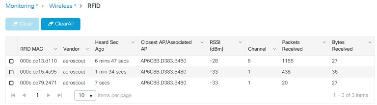
Checking RFID on WLC GUI
To check RFID from WLC GUI:
Configuring Flexible Antenna Port
The IW-6300H access point antenna connectors are located on the top of each model (see Antenna Ports of IW-6300H Access Points). The flexible antenna port can be configured via software to support dual band or single band antennas.
When configured for dual band mode, antenna ports A and B are used to support multiple input/output (MIMO) operation on both 2.4 and 5 GHz radios.
When configured for single band mode, antenna ports A and B support MIMO operation on the 2.4 GHz radio and antenna ports C and D support MIMO operation on the 5 GHz radio.
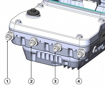
|
1 |
Antenna port B - Type N connector Wi-Fi 2.4/5 GHz TX/RX |
3 |
Antenna port D - Type N connector Wi-Fi 5 GHz TX/RX |
|
2 |
Antenna port C - Type N connector Wi-Fi 5 GHz TX/RX |
4 |
Antenna port A - Type N connector Wi-Fi 2.4/5 GHz TX/RX |
Configuration From IOS-XE WLC
The configuration of flexible antenna port is supported on IOS-XE WLC from Release 17.3.x. For detailed information, see Cisco Catalyst 9800 Series Wireless Controller Software Configuration Guide, Cisco IOS XE Amsterdam 17.3.x.
Configuration From AireOS WLC CLI
Use the following command to configure antenna band mode:
(Cisco Controller) >config ap antenna band-mode {single | dual } < AP_name >
The Antenna Band mode can be displayed by issuing the command:
(Cisco Controller) >show ap config {802.11a |b } <AP_name >
(Cisco Controller) >show ap config general <AP_name >
The output will contain many fields, one of which is the Antenna Band Mode as shown below:
Antenna Band Mode ............................... Dual
Example
(wlc-3504) >config ap antenna band-mode single IW6300DCW
Changing the antenna band mode may strand mesh APs.
Are you sure you want to continue? (y/N)y
(wlc-3504) >show ap config 802.11a IW6300DCW
Cisco AP Identifier.............................. 14
Cisco AP Name.................................... IW6300DCW
Country code..................................... US  - United States
Regulatory Domain allowed by Country.............  802.11bg:-AB    802.11a:-AB
Antenna Band Mode ............................... Dual
.....
(wlc-3504) >show ap config general IW6300DCW
Cisco AP Identifier.............................. 14
Cisco AP Name.................................... IW6300DCW
.....
Antenna Band Mode ............................... Single
.....
For dual band mode, choose only ANT-A/B for both 2.4G and 5G. For single band mode, choose ANT-A/B for 2.4G, and ANT-C/D for 5G. You can choose one antenna or two antennas in corresponding radio.
Use the following command to choose corresponding antenna:
config {802.11a |802.11b } 11nSupport antenna <AP_name > {A |B } {enable |disable }
Example
(wlc-3504) >config 802.11a disable IW6300DCW
(wlc-3504) >config 802.11a 11nSupport antenna IW6300DCW B disable
(wlc-3504) >config 802.11a 11nSupport antenna IW6300DCW A enable
(wlc-3504) >config 802.11a enable IW6300DCW
Checking Status from AP Side
Use the following command to check the status from AP side:
IW6300DCW#show capwap client config
AdminState                         : ADMIN_ENABLED(1)
Name                               : IW6300DCW
Slot 0 Config:
    Radio Type                : RADIO_TYPE_80211bg
    Antenna Band Mode         : Antenna Sector B
Slot 1 Config:
    Radio Type                : RADIO_TYPE_80211a
    Antenna Band Mode         : Antenna Sector B
In the output, Antenna Sector B means Dual Band mode, and Antenna Sector A means Single Band mode.
Configuration From AireOS WLC GUI
To change the antenna band mode from WLC GUI, go to the Wireless > Access Point > AP_NAME > Advanced tabs, and then select Dual /Single .
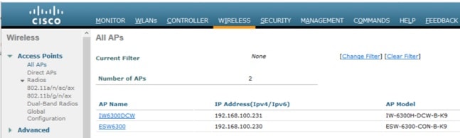
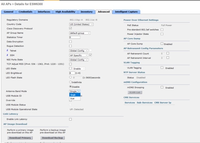
A warning message will be displayed on a popup window: “A|B|C|D” corresponding to IW6300 Panel antenna port. Click OK to make the change.
To choose corresponding antenna from WLC GUI, go to Wireless > Access Points > Radios > {802.11a/n/ac/ax | 802.11b/g/n/ax} > AP name > Configure .
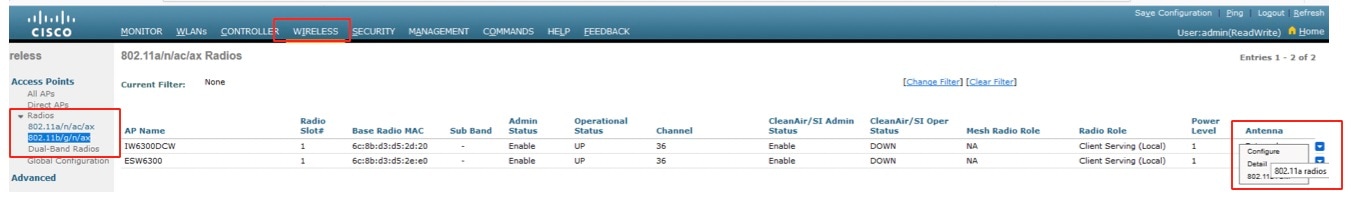
Go to the AP Radio Configure Tab and choose corresponding antenna.
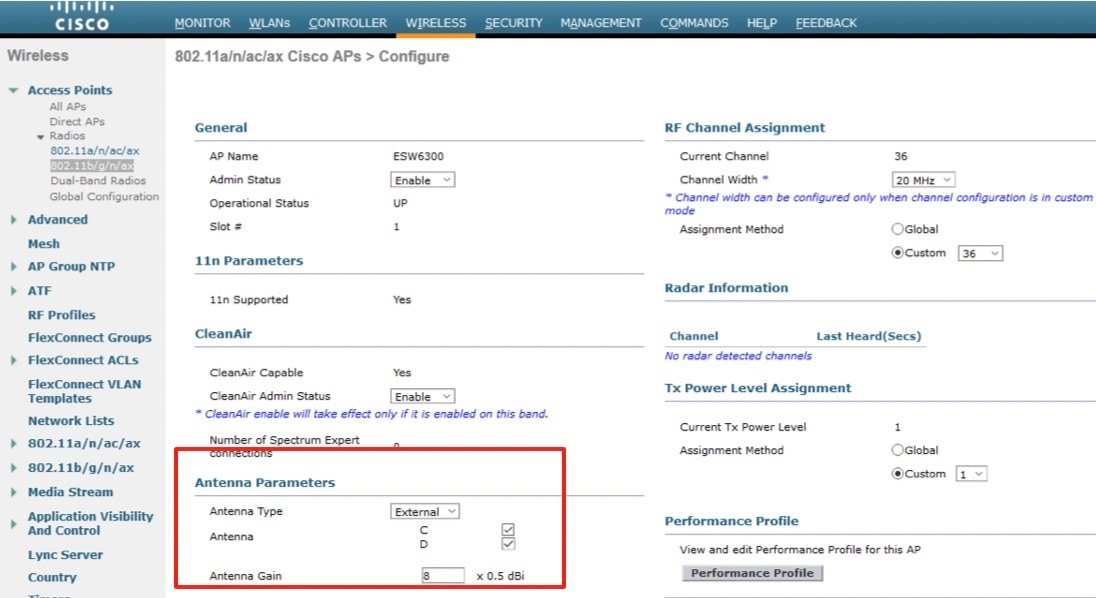
Configuration From AireOS ME GUI
To change the antenna band mode from ME GUI, go to Wireless Settings > Access Points > click config bottom of AP >, then select the Antenna Band mode Single /Dual .
To choose corresponding antenna from ME GUI, go to Wireless Settings > Access Points > click config bottom of AP >, then select Antenna A/B for Radio 1/2.
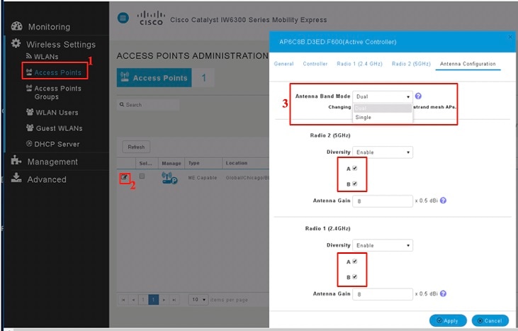
IOx Configuration
IOx is Cisco’s implementation of “Fog Computing”. IOx enables hosting of applications and services developed by Cisco. The IOx application can be easily deployed by Cisco IOx fog director, it’s partners and third party developers in the network edge devices in a seamless fashion across diverse and disparate hardware platforms.
With IOx support, IoT partners can enable application and services on the IW6300 and ESW6300 access points.
IOx function is officially supported from Release 8.10. IOx is not supported to be deployed on AP with Mobility Express image. IOx feature can be configured from AireOS Controller and AP side, but not supported on IOS-XE WLC.
Computing Resource on AP
Applications quantity:
Recommend to deploy only one APP.
CPU:
IOx applications could consume 25% of total CPU resource(50% of CPU0). IOx apps will not impact AP normal data forwarding.
Memory:
Maximum 200MB
Disk:
Maximum 32MB
IOx Configuration on AireOS Controller (WLC/ME)
Note |
IOx can be configured by AireOS Controller while AP is in non-default ap-group. For ME deployment, you need to disable Efficient Join from ME GUI → Management → Software Update → Efficient Join, to avoid capwap AP upgrading to ME image. |
Follow these steps to configure IOx on AireOS controller:
SUMMARY STEPS
- Configure AP to apgroup from GUI or CLI.
- Enable App Host on apgroup from CLI. IOx on all AP in this ap-group will be enabled.
DETAILED STEPS
| Step 1 |
Configure AP to apgroup from GUI or CLI.
|
| Step 2 |
Enable App Host on apgroup from CLI. IOx on all AP in this ap-group will be enabled. config ap apphost apgroup <group-name> {enable |disable } Example: |
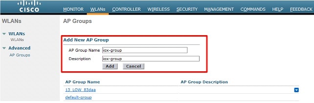
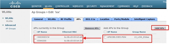
Verifying the Configuration
Use the following commands to verify your configuration:
(wlc-3504) >show ap apphost ap-name IW6300DCW
App Host configuration:
App Host Status.............: Enabled

(wlc-3504) >show ap apphost apgroup iox-group
App Host configuration:
App Host Status.............: Enabled
Related Documentation
-
Release Notes for Cisco Wireless Controllers and Lightweight Access Points for Cisco Wireless releases
-
Cisco Wireless Solutions Software Compatibility Matrix
https://www.cisco.com/c/en/us/td/docs/wireless/compatibility/matrix/compatibility-matrix.html
-
Cisco Wireless Controller Configuration Guides
-
Release Notes for Cisco Mobility Express
https://www.cisco.com/c/en/us/support/wireless/mobility-express/products-release-notes-list.html
-
Cisco IOS XE documentation
http://www.cisco.com/c/en/us/products/ios-nx-os-software/ios-xe/index.html
 Feedback