
Cisco C9610 Series Line Card Installation Note
Cisco C9610 line cards
This document describes the features of the line cards supported by Cisco C9610R series smart switches. It also provides information about how to install or replace a line card in the chassis.
This table lists the supported line cards.
|
Product ID |
Description |
|---|---|
|
C9610-LC-32CD |
Cisco C9610 series 30-port 100G/40G, 2-port 400G/100G/40G module |
|
C9610-LC-40YL4CD |
Cisco C9610 series 40-port 50G/25G/10G/1G, 2-port 200G/100G/40G, 2-port 400G/200G/100G/40G module |
|
Line cards supported with the LC adapter C9610-LC-ADPT |
|
|
C9600-LC-40YL4CD |
Cisco Catalyst 9600 series 40-port 50G/ 25G/10G/1G, 2-port 200G/100G/40G, 2-port 400G/200G/100G/40G module |
|
C9600-LC-48TX |
Cisco Catalyst 9600 series 48-port 10G/1G module |
|
C9600X-LC-32CD |
Cisco Catalyst 9600 series 30-port 100G/40G, 2-port 400G/100G/40G module |
|
C9600X-LC-56YL4C |
Cisco Catalyst 9600 series 56-port 50G/25G/10G/1G, 4-port 100G/40G module |
C9610-LC-32CD
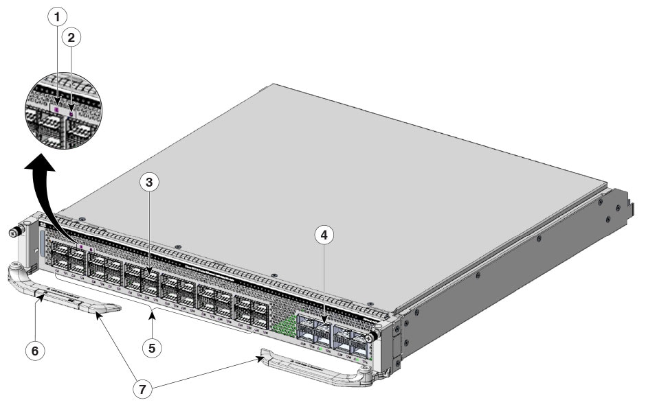
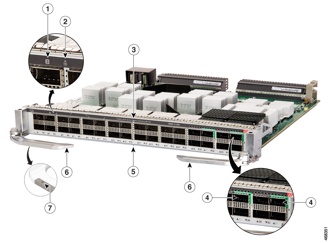
C9610-LC-32CD is a 30-port 100G/40G, 2-port 400G/100G/40G module. It supports 30 QSFP28 ports that support 100G/40G and 2 QSFP-DD ports that support 400G/100G/40G.
This illustration shows the front view of C9610-LC-32CD with major features identified.
|
1 |
Status LED |
5 |
Port link LEDs |
|
2 |
Locate or blue beacon LED |
6 |
Optional RFID embedded on the left ejector lever |
|
3 |
24 QSFP28 ports |
7 |
Ejector levers |
|
4 |
4 QSFP-DD ports |
- |
- |
Features of C9610-LC-32CD
This section describes the features supported on C9610-LC-32CD.
-
Ports per module: By default, provides 24 QSFP28 ports and 4 QSFP-DD ports. QSFP28 ports support 100G or 40G speed, whereas QSFP-DD ports support 400G/100G/40G speeds.
Supports the following three modes:
- 100G connectivity on all 32 ports, by default.
- 100G connectivity on 24 ports and 400G connectivity on 2 QSFP-DD ports in both the port groups.
- Cisco QSFP to SFP or SFP+ adapter (QSA) adapter (CVR-QSFP-SFP10G) support: Provides 10G/1G connectivity on all the QSFP ports, depending on the supervisor module installed.
- Supervisor module compatibility: Supports both Cisco C9610 Series Supervisor 3 module (C9610-SUP-3) and Cisco C9610 Series Supervisor 3XL module (C9610-SUP-3XL).
- Chassis line card slot support: Slots 1, 2, 3, 4, 7, 8, 9, and 10 are supported.
- Bandwidth per slot: 6.4 Tbps full-duplex per slot.
C9610-LC-40YL4CD
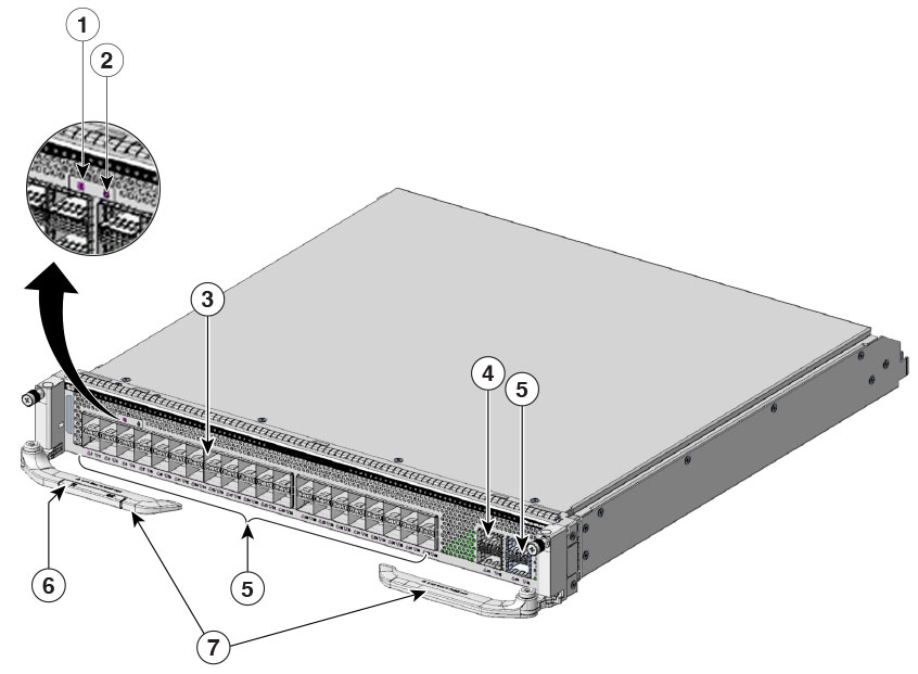
C9610-LC-40YL4CD is a 40-port 50G/25G/10G/1G, 2-port 200G/100G/40G, 2-port 400G/200G/100G/40G module. It supports 40 SFP56 ports of 50G/25G/10G/1G, two QSFP56 ports of 200G/100G/40G, and two QSFP-DD ports of 400G/200G/100G/40G.
|
1 |
Status LED |
5 |
2 QSFP-DD ports |
|
2 |
Locate or blue beacon LED |
6 |
Port link LEDs |
|
3 |
40 SFP56 ports |
7 |
Optional RFID embedded on the left ejector lever |
|
4 |
2 QSFP56 ports |
8 |
Ejector levers |
Features of C9610-LC-40YL4CD
These features are supported on C9610-LC-40YL4CD.
- Ports per module: Provides 40 SFP56 ports, 2 QSFP56 ports and 2 QSFP-DD ports. SFP56 ports support 50G or 25G or 10G or 1G, whereas QSFP56 ports support 200G/100G/40G and QSFP-DD ports support 400G/200G/100G/40G speeds.
- Supervisor module compatibility: Supports both Cisco C9610 Series Supervisor 3 module (C9610-SUP-3) and Cisco C9610 Series Supervisor 3XL module (C9610-SUP-3XL)
- Cisco QSFP to SFP or SFP+ adapter (QSA) adapter (CVR-QSFP-SFP10G) support: Provides 10G connectivity on all the QSFP ports.
- Chassis line card slot support: Slots 1, 2, 3, 4, 7, 8, 9, and 10 are supported.
- Bandwidth per slot: 6.4 Tbps full-duplex per slot.
C9600-LC-40YL4CD
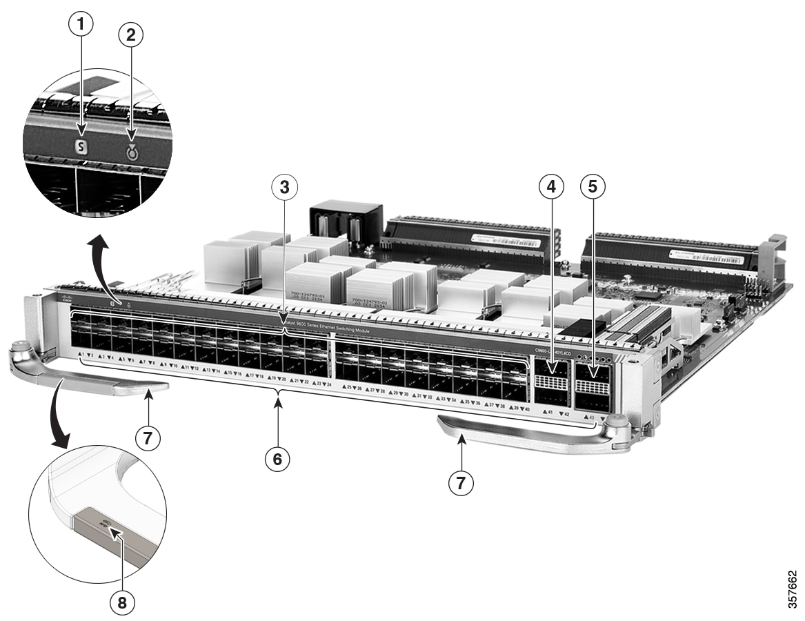
C9600-LC-40YL4CD is a 40-port 50G/25G/10G/1G, 2-port 200G/100G/40G, 2-port 400G/200G/100G/40G module. It supports 40 SFP56 ports of 50G/25G/10G/1G, two QSFP56 ports of 200G/100G/40G, and two QSFP-DD ports of 400G/200G/100G/40G.
|
1 |
Status LED |
5 |
2 QSFP-DD ports |
|
2 |
Locate or blue beacon LED |
6 |
Port link LEDs |
|
3 |
40 SFP56 ports |
7 |
Ejector levers |
|
4 |
2 QSFP56 ports |
8 |
Optional RFID embedded on the left ejector lever |
Features of C9600-LC-40YL4CD
These features are supported on C9600-LC-40YL4CD.
- Ports per module: Provides 40 SFP56 ports, 2 QSFP56 ports and 2 QSFP-DD ports. SFP56 ports support 50G or 25G or 10G or 1G, whereas QSFP56 ports support 200G/100G/40G and QSFP-DD ports support 400G/200G/100G/40G speeds.
- Supervisor module compatibility: Supports both Cisco C9610 Series Supervisor 3 module (C9610-SUP-3) and Cisco C9610 Series Supervisor 3XL module (C9610-SUP-3XL)
- Cisco QSFP to SFP or SFP+ adapter (QSA) adapter (CVR-QSFP-SFP10G) support: Provides 10G connectivity on all the QSFP ports.
- Chassis line card slot support: Slots 1, 2, 3, 4, 7, 8, 9, and 10 are supported.
- Bandwidth per slot: 6.4 Tbps (3.2 Tbps full-duplex) per slot.
C9600-LC-48TX
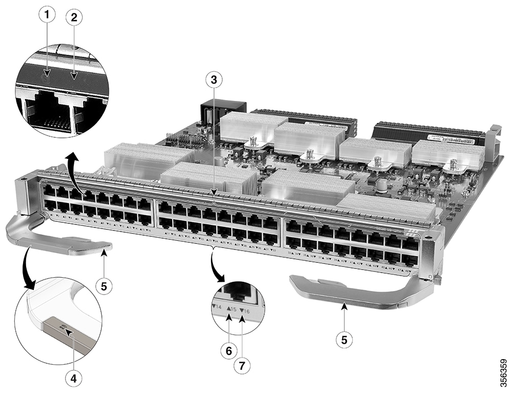
C9600-LC-48TX is a 48-port 10G/1G module. It supports 48 Multigigabit Ethernet RJ45 copper ports that support 10G/1G.
|
1 |
Status LED |
5 |
Ejector levers |
|
2 |
Locate or blue beacon LED |
6 |
Port link LED for the port in the top row |
|
3 |
48 10G/1G RJ45 copper ports |
7 |
Port link LED for the port in the bottom row |
|
4 |
Optional RFID embedded on the left ejector lever |
- |
- |
Features of C9600-LC-48TX
This section describes the features supported on C9600-LC-48TX.
-
Ports per module:
- Provides 48 RJ-45 ports.
- RJ-45 ports support 10G or 1G speeds.
- Supervisor module compatibility: Supports Cisco C9610 Series Supervisor 3 module (C9610-SUP-3) and Cisco C9610 Series Supervisor 3XL module (C9610-SUP-3XL).
- Chassis line card slot support: Slots 1, 2, 3, 4, 7, 8, 9, and 10 are supported.
- Bandwidth per slot: 960 Gbps (480 Gbps full-duplex) per slot.
C9600X-LC-32CD
C9600X-LC-32CD is a 30-port 100G/40G, 2-port 400G/100G/40G module. It supports 30 QSFP28 ports that support 100G/40G and 2 QSFP-DD ports that support 400G/100G/40G.
This illustration shows the front view of C9600X-LC-32CD with major features identified.
|
1 |
Status LED |
5 |
Port link LEDs |
|
2 |
Locate or blue beacon LED |
6 |
Ejector levers |
|
3 |
30 QSFP28 ports |
7 |
Optional RFID embedded on the left ejector lever |
|
4 |
2 QSFP-DD ports |
- |
- |
Features of C9600X-LC-32CD
This section describes the features supported on C9600X-LC-32CD.
-
Ports per module: By default, provides 30 QSFP28 ports and 2 QSFP-DD ports. QSFP28 ports support 100G or 40G speed, whereas QSFP-DD ports support 400G/100G/40G speeds.
Supports the following three modes:
- 100G connectivity on all 32 ports, by default.
- 100G connectivity on 28 ports and 1 x 400G on the QSFP-DD port in a port group.
- 100G connectivity on 24 ports and 2 x 400G on the QSFP-DD ports in both the port groups.
- Cisco QSFP to SFP or SFP+ adapter (QSA) adapter (CVR-QSFP-SFP10G) support: Provides 10G/1G connectivity on all the QSFP ports, depending on the supervisor module installed.
- Supervisor module compatibility: Supports both Cisco C9610 Series Supervisor 3 module (C9610-SUP-3) and Cisco C9610 Series Supervisor 3XL module (C9610-SUP-3XL).
- Chassis line card slot support: Slots 1, 2, 3, 4, 7, 8, 9, and 10 are supported.
- Bandwidth per slot: 6.4 Tbps (3.2 Tbps full-duplex) per slot.
C9600X-LC-56YL4C
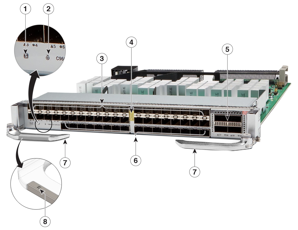
C9600X-LC-56YL4C is a 56-port 50G/25G/10G/1G, 4-port 100G/40G module. It supports 56 SFP56 ports of 50G/25G/10G/1G and 4 QSFP28 ports of 100G/40G.
This illustration shows the front view C9600X-LC-56YL4C with the major features identified.
|
1 |
Status LED |
5 |
4 QSFP28 ports
|
|
2 |
Locate or blue beacon LED |
6 |
Port link LEDs |
|
3 |
56 SFP56 ports
|
7 |
Ejector levers |
|
4 |
Sharp-edged hazard icon |
8 |
Optional RFID embedded on the left ejector lever |
Features of C9600X-LC-56YL4C
This section describes the features supported on C9600X-LC-56YL4C.
-
Per ports module:
- Provides 56 SFP56 ports of 50G or 25G or 10G or 1G speeds.
- Provides 4 QSFP28 ports of 100G or 40G speeds.
- Supervisor module compatibility: Supports Cisco C9610 Series Supervisor 3 module (C9610-SUP-3) and Cisco C9610 Series Supervisor 3XL module (C9610-SUP-3XL).
- Chassis line card slot support: Slots 1, 2, 3, 4, 7, 8, 9, and 10 are supported.
- Bandwidth per slot: 6.4 Tbps (3.2 Tbps full-duplex) per slot.
 Note
NoteCisco QSFP to SFP or SFP+ adapter (QSA) adapter (CVR-QSFP-SFP10G) is not supported on this line card.
Line card LEDs
This table describes the line card LED position or color.
|
LED type |
LED position or color |
Description |
|
|---|---|---|---|
 Blue beacon |

Blue |
Indicates that the module requires attention. Provisioned by the administrator of the system. |
|
|
Blink fast |
Indicates that the module requires attention. The LED blinks at a rate of 0.6 seconds. |
||
|
Blink slow |
Indicates that the module requires attention. Configured by the user, the LED blinks at a rate of 1.2 seconds. |
||
|
Off |
Indicates that the module does not need any attention. |
||
 Status LED |

Green |
Indicates that all diagnostic tests have passed and the module is operational. |
|

Red |
Indicates major environmental alarms, if the module is online. |
||

Amber |
Indicates minor environmental alarms, if the module is online. |
||
|
Off |
Indicates that the module is disabled or is not powered up. |
||
 Port LED |
Green |
Port link is up. |
|
|
Amber |
Port link is disabled, that is, administratively down. |
||
|
Off |
No signal is detected, the link is down, or the port is not connected. |
||
|
Alternating Green and Amber |
Indicates port beacon. |
||

Blinking Amber |
Indicates link faults such as excessive collision errors. |
||

Blinking Green |
Indicates traffic on the port. |
||
| Traffic utilization | Blinking rate | ||
|
Less than 5% |
Nil |
||
|
Between 5% and 30% |
At a rate of 1.2 seconds. |
||
|
Between 30% and 70% |
At a rate of 0.4 seconds. |
||
|
More than 70% |
At a rate of 0.2 seconds. |
||
Preparing for installation or removal of a line card
Before you install or remove a line card on a Cisco C9610 series smart switch
- adhere to the safety requirements,
- refer how to prevent ESD damage, and
- ensure that you have the right tools.
Safety warnings
Safety warnings appear throughout this publication in procedures that may harm you if you perform them incorrectly. A warning symbol precedes each warning statement. The warnings below are general warnings that are applicable to the entire publication.
 Warning
Statement 1071—Warning Definition
IMPORTANT SAFETY INSTRUCTIONS
Before you work on any equipment, be aware of the hazards involved with electrical circuitry and be familiar with standard practices for preventing accidents. Read the installation instructions before using, installing, or connecting the system to the power source. Use the statement number at the beginning of each warning statement to locate its translation in the translated safety warnings for this device.
SAVE THESE INSTRUCTIONS
 Warning
Statement 445—Connect the Chassis to Earth Ground
To reduce the risk of electric shock, connect the chassis of this equipment to permanent earth ground during normal use.
WarningStatement 1008—Class 1 Laser Product
This product is a Class 1 laser product.
WarningStatement 1029—Blank Faceplates and Cover Panels
Blank faceplates and cover panels serve three important functions: they reduce the risk of electric shock and fire, they contain electromagnetic interference (EMI) that might disrupt other equipment, and they direct the flow of cooling air through the chassis. Do not operate the system unless all cards, faceplates, front covers, and rear covers are in place.
WarningStatement 1055—Class 1/1M Laser
Invisible laser radiation is present. Do not expose to users of telescopic optics. This applies to Class 1/1M laser products.
 Warning
Statement 1073—No User-Serviceable Parts
There are no serviceable parts inside. To avoid risk of electric shock, do not open.
WarningStatement 1056—Unterminated Fiber Cable
Invisible laser radiation may be emitted from the end of the unterminated fiber cable or connector. Do not view directly with optical instruments. Viewing the laser output with certain optical instruments, for example, eye loupes, magnifiers, and microscopes, within a distance of 100 mm, may pose an eye hazard.
WarningStatement 1074—Comply with Local and National Electrical Codes
To reduce risk of electric shock or fire, installation of the equipment must comply with local and national electrical codes.
NoteStatement 1089—Instructed and Skilled Person Definitions
An instructed person is someone who has been instructed and trained by a skilled person and takes the necessary precautions when working with equipment.
A skilled person or qualified personnel is someone who has training or experience in the equipment technology and understands potential hazards when working with equipment.
WarningStatement 1090—Installation by Skilled Person
Only a skilled person should be allowed to install, replace, or service this equipment. See statement 1089 for the definition of a skilled person.
WarningStatement 1091—Installation by an Instructed Person
Only an instructed person or skilled person should be allowed to install, replace, or service this equipment. See statement 1089 for the definition of an instructed or skilled person.
WarningStatement 1099—Before Connecting to System Power Supply
High touch/leakage current—Permanently connected protective earth ground is essential before connecting to the system power supply.
NoteStatement 7001—ESD Mitigation
This equipment may be ESD sensitive. Always use an ESD ankle or wrist strap before handling equipment. Connect the equipment end of the ESD strap to an unfinished surface of the equipment chassis or to the ESD jack on the equipment if provided.
WarningStatement 9001—Product Disposal
Ultimate disposal of this product should be handled according to all national laws and regulations.
Prevent ESD damage
An electrostatic discharge (ESD) strap, is a tool used to prevent damage to sensitive electronic components from static electricity. It is a wrist strap that connects the wearer to a grounding point, ensuring that any static charge on the body is safely dissipated to the ground, thus preventing damage to electronic components during handling.
ESD damage might occur when modules or other field replaceable units (FRUs) are improperly handled, resulting in intermittent or complete failure of the modules or FRUs. Modules consist of printed circuit boards that are fixed in metal carriers. EMI shielding and connectors are integral components of a carrier. Although the metal carrier helps to protect the board from ESD, always use an ESD-grounding strap when handling modules. To prevent ESD damage, follow these guidelines.
- Always use an ESD wrist or ankle strap and ensure that it makes good skin contact.
- Connect the equipment end of the strap to an unfinished chassis surface.
- When installing a component, use an available ejector lever to properly seat the bus connectors in the backplane or midplane. These devices prevent accidental removal, provide proper grounding for the system, and help to ensure that bus connectors are properly seated.
- When removing a component, use an available ejector lever to release the bus connectors from the backplane or midplane.
- Handle carriers by available handles or edges only; avoid touching the printed circuit boards or connectors.
- Place a removed component board-side-up on an antistatic surface or in a static-shielding container. If you plan to return the component to the factory, immediately place it in a static-shielding container.
- Avoid contact between the printed circuit boards and clothing. The wrist strap only protects components from ESD voltages on the body; ESD voltages on clothing can still cause damage.
- Never attempt to remove the printed circuit board from the metal carrier.
Tools required
You need these tools to install or remove supervisor engines and line cards.
- Your own ESD-prevention equipment or the disposable grounding wrist strap included with all upgrade kits, FRUs, and spares.
- Antistatic mat or antistatic bag
Installing a line card
 Caution Attention
Ensure that the ejector on both sides of the line card is fully locked into the chassis after it is installed into chassis.
Before you begin
WarningStatement 1055—Class 1/1M Laser
Invisible laser radiation is present. Do not expose to users of telescopic optics. This applies to Class 1/1M laser products.
- Take the necessary precautions to prevent ESD damage. Wear a grounded ESD wrist strap while handling the line cards.
- Ensure that you have enough clearance to accommodate any interface equipment that you will connect directly to the ports.
Step 1 | Remove the slot blank cover (C9610-LC-BLANK=) if it is present, by squeezing the release handles towards each other (with your thumb and index fingers) and sliding the cover out of the bay. Save it for future use. |
Step 2 | Remove the new line card from the shipping packaging, being careful to handle the module using only the module’s metal tray or the front panel. Do not touch the printed circuit board or the connector pins. |
Step 3 | Position and carefully slide the line card into the slot. Make sure that you align the sides of the printed circuit boards with the slot guides on each side of the chassis slot. 
In PDF, to view the animation, click this link. |
Step 4 | Half-way through the installation, pivot the left and the right ejector levers away from the front of the module and hold them while sliding the line card completely into the slot. 
In PDF, to view the animation, click this link. 
In PDF, to view the animation, click this link. |
Step 5 | Pivot both the ejector levers inward simultaneously. Make sure that you pivot the ejector levers only after the line card is seated completely inside the slot. 
In PDF, to view the animation, click this link. |
Step 6 | Tighten the captive screws on both sides to secure the line card to the chassis. |
Step 7 | Install necessary transceivers, if any, into the module ports. For installation instructions along with safety warnings for the various types of transceivers, see https://www.cisco.com/en/US/products/hw/modules/ps5455/prod_installation_guides_list.html |
Step 8 | Attach the necessary network interface cables or other devices to the interface ports. |
Step 9 | Check the status of the line card:
|
Removing a line card
WarningStatement 1051—Laser Radiation
Invisible laser radiation may be emitted from disconnected fibers or connectors. Do not stare into beams or view directly with optical instruments.
CautionTo prevent ESD damage, handle line cards by the carrier edges only.
Before you begin
- You will need a slot blank cover (C9610-LC-BLANK=) if the slot is to remain empty.
- Take the necessary precautions to prevent ESD damage. Wear a grounded ESD wrist strap while handling the modules.
Step 1 | Disconnect network interface cables, if any, that are attached to the line card ports. |
Step 2 | If the line card is equipped with removable optical transceivers, immediately install dust plugs into the transceiver’s optical bores. This prevents possible dust contamination, which can affect port performance. |
Step 3 | Unscrew the captive screws on both sides of the line card. 
In PDF, to view the animation, click this link. |
Step 4 | Grasp the left and right ejector levers and simultaneously rotate the levers outward to disengage the line card from the backplane connector. 
In PDF, to view the animation, click this link. |
Step 5 | Grasp the front panel of the line card with one hand and place your other hand under the carrier to support and guide it out of the slot. Do not touch the printed circuit boards or connector pins. |
Step 6 | Carefully slide the line card straight out of the slot, keeping your other hand under the carrier to guide it. 
In PDF, to view the animation, click this link. |
Step 7 | Place the line card on an antistatic mat or in an antistatic bag. |
Step 8 | Install a replacement line card after a 15-second wait. Alternatively, if the chassis slot is to remain empty, install a blank slot cover (C9610-LC-BLANK=). Remove slot blanks only when installing a line card. If a line card is removed, ensure that you replace it with a slot blank immediately. Also, keep the line card in ESD-protective bags when they are not installed in a chassis. WarningStatement 1029—Blank Faceplates and Cover Panels Blank faceplates and cover panels serve three important functions: they reduce the risk of electric shock and fire, they contain electromagnetic interference (EMI) that might disrupt other equipment, and they direct the flow of cooling air through the chassis. Do not operate the system unless all cards, faceplates, front covers, and rear covers are in place. |
Installing a line card adapter
To use C9600-LC-40YL4CD, C9600-LC-48TX, C9600X-LC-32CD, or C9600X-LC-56YL4C, you must first install the C9610-LC-ADPT on the C9610R chassis.
You can directly install C9610-LC-32CD and C9610-LC-40YL4CD in the line card slots in the C9610R chassis.
Perform this task to install the line card adapter, C9610-LC-ADPT.
Step 1 | Remove the line card adapter C9610-LC-ADPT from the shipping packaging, being careful to handle the module using only the module’s metal tray or the front panel. |
Step 2 | Position the line card adapter with the slot and slowly slide it in. 
In PDF, to view the animation, click this link. |
Step 3 | Half-way through the installation, press the buttons with arrows to release the ejector levers on both sides of the line card adapter and holding the ejector levers, slide the adapter into the slot completely. 
In PDF, to view the animation, click this link. |
Step 4 | Once the line card adapter is completely seated in the slot, pivot both the ejector levers inward simultaneously to lock the adapter. 
In PDF, to view the animation, click this link. |
Step 5 | Screw in the captive screws on both sides of the line card adapter to secure it to the chassis. 
In PDF, to view the animation, click this link. |
What's next
After installing the line card adapter, follow the steps in the Installing a line card section to install C9600-LC-40YL4CD, C9600-LC-48TX, C9600X-LC-32CD, or C9600X-LC-56YL4C inside C9610-LC-ADPT.
Removing a line card adapter
Before you begin
Before removing the line card adapter, you must disconnect network interface cables, if any, that are attached to the line card ports, and remove the line card.
Perform this task to remove the line card adapter, C9610-LC-ADPT.
Step 1 | To remove the line card adapter, unscrew the captive screws on both sides. 
To view the animation in PDF, click this link. |
Step 2 | Press the buttons (denoted with arrows) on both the ejector levers to release the levers. This unlocks the adapter. 
To view the animation in PDF, click this link. |
Step 3 | Grasp the left and right ejector levers and simultaneously pull out the line card adapter.
|
Step 4 | Holding both sides of the line card adapter, slide it completely out of the slot. 
To view the animation in PDF, click this link. |
What to do next
After installing the line card adapter, follow the steps in the Removing a line card section to remove a line card from C9610-LC-ADPT.