cnSGW-C Overview

Product Description

cnSGW-C is a Control Plane Network Function (NF) of the converged core network (4G-5GC). The Serving Gateway Control Plane Function (cnSGW-C) is built on top of the SMI architecture. cnSGW-C acts as a UE anchor and supports mobility procedures, along with session setup and termination procedures, as specified in 3GPP TS 23.401 and 3GPP TS 23.214.

The Serving Gateway Control Plane Function (cnSGW-C) provides the functionality of the S-GW as defined by TS 23.401 [2], except for the functions that are performed by the SGW-U, as described in 3GPP Spec 23.214 Table 4.3.2-1. In addition, the cnSGW-C is responsible for selecting the SGW-U (as described in 3GPP Spec 23.214 clause 4.3.3) and for controlling the SGW-U with respect to the functions described in TS 23.214 Table 4.3.2-1.

With SMF (IWF) support based on Cisco Cloud Native Platform, it is recommended to support cnSGW-C functionality on Cloud Native Platform for better hardware utilization and O&M activities.

Converged Core Overview

The converged core solution provides an advanced, cloud-native, converged control plane with the capability to support 4G and 5G devices, and use cases.


Important


This release supports only the cloud-native integrated S-GW and 5GSA GW instance with S5C and cnSGW-C functionalities.


The converged core solution removes the operational complexity by providing a unified core network to handle all types of subscribers and use cases.

The operator has the following benefits:

  • Improves the overall network efficiency by reducing signaling between cnSGW-C and 5GSA GW while handling a 4G subscriber or handoff from 5G to 4G coverage area.

  • Reduces latency introduced due to the extra hop SGW-U for a subscriber in 4G coverage area, by collapsing the data path in the Converged UPF, thus improving the overall user experience.

  • Provides ability to use a unified subscriber policy and billing infrastructure using SBA interfaces for 4G and 5G devices.

The solution supports the following converged control plane and user plane functions:

  • Converged Control Plane Functions

    • Integrates S-GW and 5GSA GW network functions as a single deployment, under a single Kubernetes namespace, to support 4G and 5G devices from E-UTRAN/NR (converged core gateway)

    • Supports logical network functions (data)

  • Converged User Plane Functions

    • Integrates UPF and SGW-U functionalities as a single network function

    • Provides simultaneous support for N4 and Sxa interfaces

    • Terminates multiple control planes in a single deployment

Converged core architecture and ULB integration

The Converged Core architecture integrates the Unified Load Balancer (ULB) with the cnSGW-C Service Pods to support direct routing of GTPC and PFCP signaling traffic. By eliminating the need for dedicated GTPC and PFCP protocol pods for ingress and egress signaling, the architecture reduces signaling latency, simplifies signaling paths, and improves scalability in cloud-native deployments.

The ULB distributes ingress signaling messages to the appropriate cnSGW-C Service Pod based on the configured load-balancing policy and routes egress signaling messages to the corresponding peer network element. The ULB maintains session affinity to ensure that all signaling messages associated with an active subscriber session are consistently processed by the same Service Pod.

The ULB provides a common routing framework for GTPC and PFCP signaling, enabling direct communication between the ULB and the cnSGW-C Service Pods. This architecture supports efficient session processing, consistent message routing, and protocol-specific peer management for supported signaling procedures.

The Converged Core ULB integration provides the following capabilities:

  • GTPC ingress and egress signaling message routing

  • PFCP ingress and egress signaling message routing

  • Session affinity for subscriber sessions

  • GTP and PFCP peer management

ULB integration in converged core

The Unified Load Balancer (ULB) integrates GTPC and PFCP signaling into the Converged Core architecture by forwarding ingress and egress signaling traffic directly to Service Pods for processing. This architecture replaces the legacy deployment model in which GTPC and PFCP signaling was processed by dedicated protocol pods.

In a ULB-enabled deployment, GTPC and PFCP signaling is processed within the Service Pod together with subscriber session management. The ULB distributes signaling traffic across available Service Pods while maintaining session affinity throughout the lifetime of the subscriber session. All signaling messages associated with a subscriber session are routed to the same Service Pod unless traffic is redistributed because of a Service Pod or node failure.

Processing GTPC and PFCP signaling within the Service Pod reduces inter-pod signaling and simplifies the signaling path between peer network functions and subscriber session processing. The ULB also supports traffic redistribution during Service Pod and node failures to maintain service continuity.

ULB integration design

The ULB integration uses the existing Unified Load Balancer infrastructure to distribute protocol signaling traffic across the available cnSGW-C Service Pods. The ULB selects a Service Pod for new session establishment and maintains routing information for subsequent protocol messages associated with the session.

For new sessions, the ULB distributes the initial signaling request across the available Service Pods. The selected Service Pod establishes ownership of the subscriber session and maintains the session information for subsequent signaling procedures.

For existing sessions, the ULB identifies the Service Pod associated with the session and forwards all subsequent signaling messages to the same Service Pod, ensuring session affinity throughout the session lifecycle.

After processing the signaling request, the Service Pod generates the appropriate response and sends it through the ULB to the peer network element.

This routing mechanism is used for both GTPC and PFCP signaling traffic.

The ULB integration feature is supported in the following deployment models:

  • Flex
  • Flex-small

Before directing signaling traffic through the ULB, deploy the required number of Service Pods and ensure that the ULB is operational. During normal operation, the ULB maintains session affinity throughout the subscriber session lifecycle. If a Service Pod or node becomes unavailable, the ULB redistributes signaling traffic to an available Service Pod to maintain service continuity.

Session routing and affinity

The ULB maintains session affinity to ensure that all protocol messages belonging to the same subscriber session are forwarded to the same cnSGW-C Service Pod.

For a new subscriber session, the ULB selects a Service Pod based on the configured load-balancing algorithm. After the session is established, the routing information is maintained so that subsequent protocol messages associated with the session continue to be processed by the selected Service Pod.

Session affinity applies to both GTPC and PFCP session-level signaling and remains valid throughout the lifetime of the subscriber session.

Call flow summary

The ULB integration supports the complete lifecycle of GTPC and PFCP signaling procedures, including session establishment, session modification, session deletion, and session release. During message processing, the ULB forwards signaling traffic to the appropriate Service Pod, where subscriber session management and protocol processing are performed. The Service Pod returns the response through the ULB to the corresponding peer network element.

ULB integration of GTPC ingress/egress traffic

Table 1. Feature history

Feature name

Release

Feature description

ULB integration of GTPC traffic

2026.03.0

This release introduces ULB-based ingress and egress routing for GTPC traffic, enabling scalable traffic distribution and session-aware message steering. The enhancement optimizes control-plane traffic handling and supports efficient scaling in cloud-native deployments.

The ULB routes GTPC ingress and egress signaling messages to the appropriate cnSGW-C Service Pod while maintaining session affinity. GTPC signaling is processed directly by the Service Pod without requiring dedicated GTPC protocol pods for ingress and egress signaling.

GTPC message routing

The ULB receives GTPC ingress signaling messages from peer network elements and forwards them to the appropriate Service Pod based on the configured load-balancing policy.

For a new subscriber session, the ULB distributes the initial GTPC signaling request to a Service Pod. The selected Service Pod processes the request and establishes the routing information required for subsequent GTPC messages.

After the session is established, the ULB maintains session affinity and forwards all subsequent session-level GTPC messages to the same Service Pod. Egress GTPC messages generated by the Service Pod are routed through the ULB to the appropriate peer network element.

The ULB supports routing of both ingress and egress GTPC signaling while maintaining consistent session processing.

GTP peer management

The Unified Load Balancer supports GTP peer management by forwarding GTP peer management messages to the appropriate processing component while maintaining independent routing for session-level signaling. Session-level GTPC signaling continues to be routed based on session affinity to the owning Service Pod, ensuring consistent session processing.

Limitations

Automatic redistribution of GTPC signaling traffic during Service Pod or node failures is not supported in the current release. When a Service Pod or node becomes unavailable, the ULB does not automatically update its forwarding information to reroute subsequent signaling messages to another Service Pod. Manual intervention may be required to restore normal signaling traffic.

ULB integration of PFCP ingress/egress traffic

Table 2. Feature history

Feature name

Release

Feature description

ULB integration for PFCP traffic

2026.03.0

This release introduces ULB-based ingress and egress routing forPFCP traffic, enabling scalable traffic distribution. The enhancementoptimizes PFCP control-plane traffic handling and supportsefficient scaling in cloud-native deployments.

The ULB routes PFCP ingress and egress signaling messages to the appropriate cnSGW-C Service Pod while maintaining session affinity. PFCP session-level signaling is processed directly by the Service Pod, while node-level peer management continues to use the existing PFCP processing framework.

PFCP message routing

The ULB receives PFCP ingress signaling messages from peer network elements and forwards them to the appropriate Service Pod based on the configured load-balancing policy.

For a new PFCP session or association, the ULB distributes the initial PFCP request to a Service Pod. The selected Service Pod processes the request and establishes the routing information required for subsequent PFCP messages.

After the session or association is established, the ULB maintains session affinity and forwards all subsequent session-level PFCP messages to the same Service Pod. Egress PFCP messages generated by the Service Pod are routed through the ULB to the appropriate peer network element.

The ULB supports routing of both ingress and egress PFCP signaling while maintaining consistent session processing.

PFCP peer management

The Unified Load Balancer differentiates between PFCP node-level and session-level signaling and routes messages to the appropriate processing component.

Node-level PFCP messages continue to use the existing PFCP processing framework, while session-level PFCP messages are forwarded to the Service Pod. The Service Pod processes PFCP session establishment, modification, and deletion procedures and maintains session affinity so that all messages belonging to an active PFCP session are consistently processed by the same Service Pod.

This routing mechanism enables separate handling of node-level and session-level PFCP signaling while maintaining consistent message processing and session affinity across the Converged Core deployment.

Use Cases

This section describes the use cases that cnSGW-C supports:

  • cnSGW-C Configuration

    The cnSGW-C base configuration provides a detailed view of configurations required for the cnSGW-C to be operational. The configuration includes setting up the infrastructure to deploy the cnSGW-C, deploying the cnSGW-C through SMI, and configuring the Ops Center for exploiting the cnSGW-C capabilities over time. For more information on SMI, see the Ultra Cloud Core SMI Cluster Deployer Operations Guide.

    The following features are related to this use case:

    For Converged Core deployment, cnSGW-C is deployed using Converged Ops Center.

  • Session Management

    Every UE accessing the EPC is associated with a single S-GW. cnSGW-C supports multiple PDN for given UE. As a part of Session Management, cnSGW-C supports the following:

    • Default and dedicated bearer establishment

    • Bearer modification

    • Bearer deactivation

    The following features are related to this use case:

  • Support for UE Mobility

    cnSGW-C is a mobility anchor point for UE. In LTE Network, there can be mobility between eNodeB to eNodeB, with or without MME change. UE can also move from one cnSGW-C to another cnSGW-C with different modes, S1-based Relocation, X2-based Relocation, and 5G-4G interworking.

    The following features are related to this use case:

  • S1-Release/Buffering/Downlink Data Notification

    cnSGW-C handles releasing S1-U bearer between eNodeB and SGW-U. When cnSGW-C receives Radio Access Bearers (RAB) message indicating that S1-U bearers are released, it updates User Plane and moves UE to IDLE state. When in IDLE state, if UE receives downlink data packet, cnSGW-C generates DDN message towards MME to page UE.

    cnSGW-C also supports DDN Throttling, DDN Delay, and High Priority feature for DDN.

    The following features are related to this use case:

  • Retransmission and Timeout

    For all procedures, as per 3GPP TS 23.401/29.274, cnSGW-C supports N3-Retransmission, and T3-Timeout Support. These are supported for S11, S5, and Sx interfaces.

    The following feature is related to this use case:

  • Failure and Error Handling

    cnSGW-C supports handling of:

    • Failure response for Create Session Request as part of initial attach procedure and additional PDN setup procedure

    • PGW-initiated Dedicated Bearer Creation (DBC) procedure failure scenario

    • Radio Access Bearers (RAB), Modify Bearer Request and Response (MBR) from PGW and User Plane

    The following feature is related to this use case:

  • Load/overload Control Functions

    cnSGW-C supports:

    • Exchange of load/overload control information and actions during peer node overload over Sx interface.

    • Handling load/overload information on GTPv2 interface.

    The following features are related to this use case:

  • cnSGW-C Charging Support

    cnSGW-C supports:

    • Offline Charging (Gz).

    • Writing CDR to local disk storage. The CDR files are pushed to SFTP server periodically.

    • CDR generation for selected subscribers. This is achieved by enabling CDR generation per Operator Policy through call control profile.

    The following feature is related to this use case:

  • Peer and Path Management for GTPC and Sx

    cnSGW-C supports:

    • Peer management for MME (S11 peers), PGW (S5 Peers), and User Plane.

    • Peer monitoring through ECHO Request/Response and Heartbeat Request/Response.

    • Handling of path failure events for S11 and S5 peers.

    The following features are related to this use case:

  • Redundancy Support

    The cnSGW-C deployment in K8 cluster plays a vital role to support High Availability (HA) and Geographic Redundancy (GR).

    The Redundancy Support ensures stateful session continuity among the clusters during the rack or cluster failures.

    The cnSGW-C achieves the HA through redundant set-up of each cluster component such that any single point of failure is avoided.

    The GR provides rack-level redundancy to replicate data between two separate K8 Clusters across rack. On RACK/Cluster failure, traffic switches to a remote RACK to process the traffic. The failure can be due to power failure, multi-compute failures, network failure, multi-POD failure, BFD link failure, and so on.

    The following features are related to this use case:

  • Dynamic Routing

    Dynamic routing enables L3 peering with Leafs, in addition to L2 Static routing.

    The following feature is related to this use case:

  • GTPU Path Management and Session Management

    The UPF notifies an Error Indication message for a GTP-U peer to the sender when a GTP-PDU is received with a TEID that does not exist. This ensures that there are no stale sessions or bearers, and maintains consistency in the network.

    Error Indication and GTP-U Path Failure Indication communication between S-GW and UPF nodes is supported over the N4 interface. For the neighbor nodes, the communication is supported over the S1u/S5u interfaces. Behavior variations of local-purge or signal-peer for Error Indication and GTP-U Path Failure are considered in this implementation.

    The following features are related to this use case:

Deployment Architecture and Interfaces

cnSGW-C is a part of the converged core network functions portfolio with a common mobile core platform architecture. The core network functions include Access and Mobility Management Function (AMF), Policy Control Function (PCF), Session Management Function (SMF), and User Plane Function (UPF).

cnSGW-C Architecture

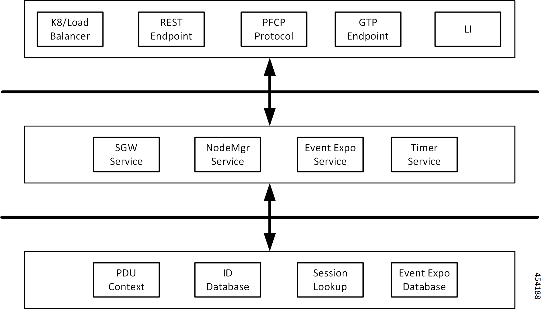
cnSGW-C network function consists of loosely coupled microservices. The microservice decomposition is based on a three-layered architecture, as illustrated in the following figure:

Figure 1. cnSGW-C Architecture

The following are the three layers of the cnSGW-C architecture:

  • Layer 1 - Protocol and Load Balancer services (Stateless)

  • Layer 2 - Application services (Stateless)

  • Layer 3 - Database services (Stateful)

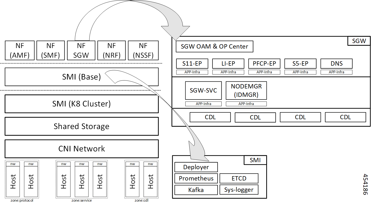
cnSGW-C Deployment

cnSGW-C NF is deployed in a separate namespace as an independent NF.

Figure 2. cnSGW-C Deployment
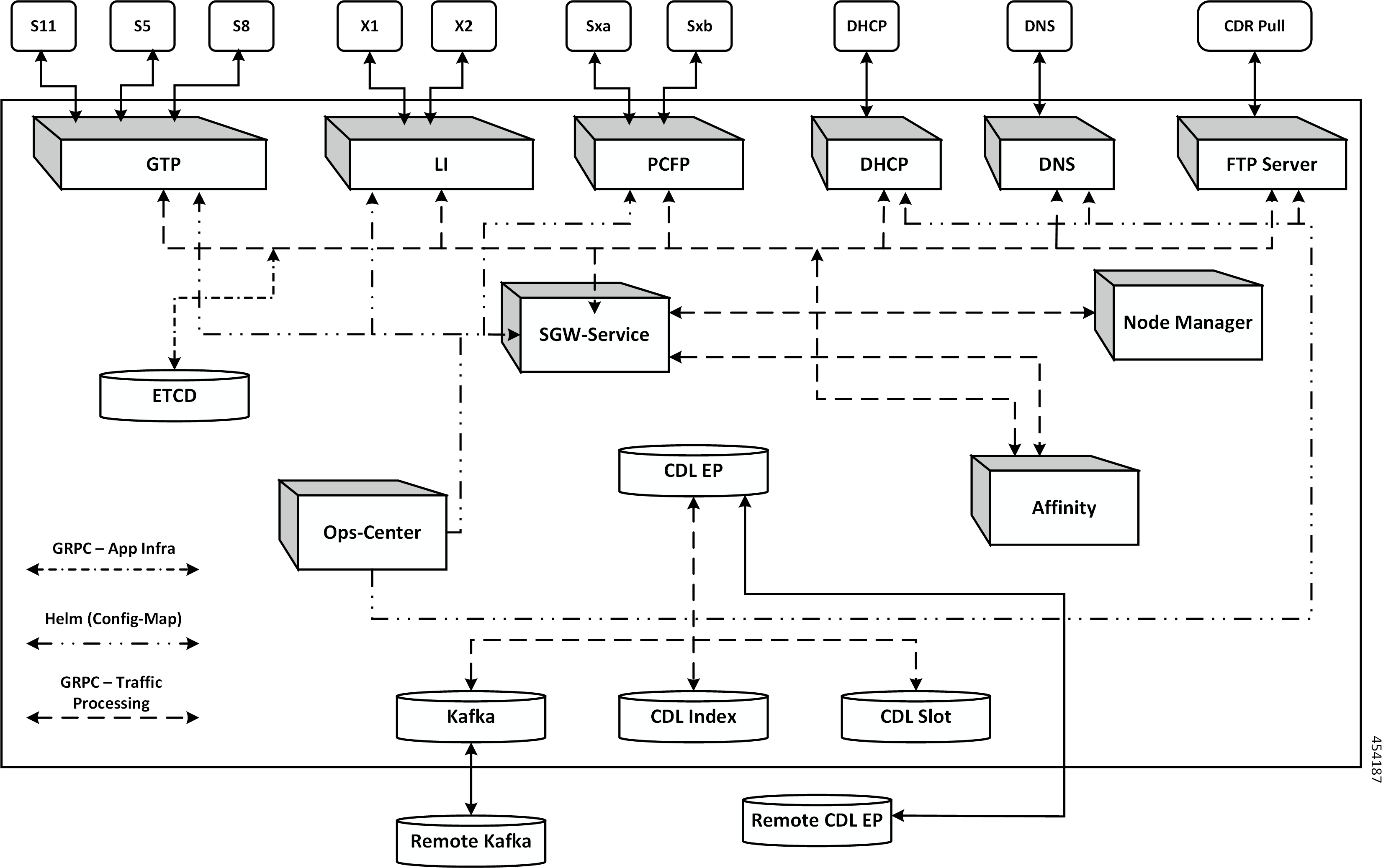
Figure 3. cnSGW-C HELM Chart

Converged Core Architecture

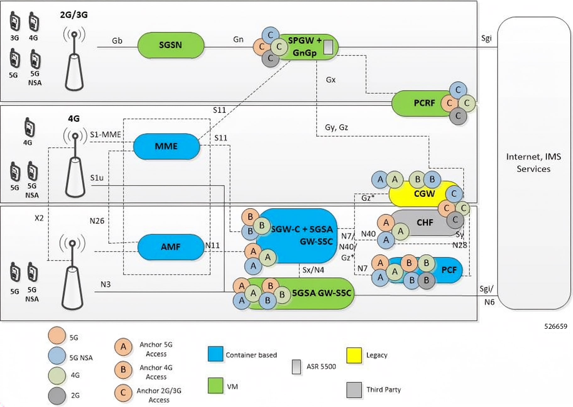
The converged core solution provides a single unified platform which is based on SMI architecture. The supporting architecture integrates the cloud-native S-GW and 5GSA GW deployment with 5GC and cnSGW-C functionalities. The solution uses 3GPP-defined SBA interfaces for policy and charging functions.

In the converged core architecture, the 4G and 5G capable UEs are anchored on the same control plane instance. The control plane instance provides the 5GSA GW, 5GC, and cnSGW-C functionalities.

The handoffs between 4G and 5G access types are seamless for 5G capable devices. The handoffs from LTE to UTRAN (bi-directional communication between 4G/5G and 3G/2G) are not seamless for 4G capable devices.

The following figure illustrates the supported network architecture.

Figure 4. Converged Core Architecture

The UPF deployed as a part of this solution is a VPC-SI VM. The UPF deployment is VM-based, and supports:

  • SGW-U, PGW-U, and UPF functionalities in the same instance, and exposes the Sxa, Sxb, Sxab, or N4 interface towards the control plane.

  • Multiple CP instances (up to 4) simultaneously.

Converged Core Deployment

The converged core deployment is based on the converged control plane and unified user plane infrastructure for all use cases.

In the converged core deployment, all 4G and 5G-capable UEs are anchored on the 5G core (5GSA GW) with SBA interfaces towards PCF.

The converged core deployment has a converged Ops Center that allows the configuration of cnSGW-C and 5GSA GW services along with other microservices. A single product helm chart is used to install components.

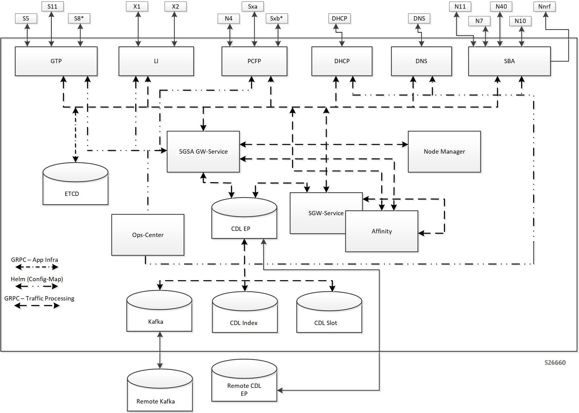
The following figure illustrates the Kubernetes deployment for the converged S-GW and 5GSA GW network function.

Figure 5. Kubernetes Deployment
Figure 6. Kubernetes Deployment

The protocol layer services are shared across 5GSA GW and S-GW. The GTP endpoint terminates the S11 interface and S5/S8 interface. Similarly, the PFCP (protocol) endpoint terminates the N4 and Sxa interfaces.

The 5GSA GW and S-GW services are deployed as distinct pods and the session processing is segregated. Both the service pods use CDL for storing subscriber sessions.

Supported Interfaces

This section describes the interfaces supported between cnSGW-C and other network functions in the 5GC.

  • S11—Reference point between the SGW and the MME

  • S5/S8—Reference point between the SGW and the PGW/SMF

  • Sxa—Reference point between the SGW-C and the SGW-U

  • Gz—Reference point between the SGW-C and the Charging Server

License Information

cnSGW-C supports Cisco Smart Licensing, a cloud-based licensing model that simplifies the purchase, deployment, and management of Cisco software assets. For more information, refer to the Smart Licensing Support collection page.

Standards Compliance

cnSGW-C complies with the following 3GPP standards:

  • 3GPP TS 23.401 "General Packet Radio Service (GPRS) enhancements for Evolved Universal Terrestrial Radio Access Network (E-UTRAN) access"

  • 3GPP TS 23.402 "Architecture enhancements for non-3GPP accesses"

  • 3GPP TS 29.274 "Evolved General Packet Radio Service (GPRS) Tunnelling Protocol for Control plane (GTPv2-C);"

  • 3GPP TS 23.214 "Architecture enhancements for control and user plane separation of EPC nodes"

  • 3GPP TS 29.244 "Interface between the Control Plane and the User Plane nodes"

  • 3GPP TS 24.008 "Mobile radio interface Layer 3 specification; Core network protocols; Stage 3"

  • 3GPP TS 23.007 "Restoration procedures"

  • 3GPP TS 22.153 "Multimedia priority service"

  • 3GPP TS 33.107 "3G security; Lawful interception architecture and functions"