Deployment Workflow

Deploy Sensor Connect on-premises on Cisco IOS XE 17.15 and 17.18

Enable Sensor Connect functionality for IoT services by installing its application and configuring networking settings on Cisco Catalyst 9800 controllers.

This task is for administrators deploying Sensor Connect in environments using Cisco IOS XE 17.15 or 17.18 and the legacy controller web UI. Proper network configuration ensures APs communicate with the Sensor Connect interface.

Procedure


Step 1

Log in to the Cisco Catalyst 9800 Wireless Controller web UI.

Step 2

Choose Configuration > Services > IoT Services.

Step 3

Enter the Sensor Connect interface IP address, subnet mask, and default-gateway IP address.

A /30 subnet provides the Sensor Connect address and VirtualPortGroup gateway address.

Step 4

If APs cannot directly reach the Sensor Connect interface, enter the NAT IP address that they use as the gRPC destination.

Step 5

In Image File Path, select the Sensor Connect image.

Step 6

Monitor the application through the Installing, Activating, Starting, and Running states.

Step 7

Verify the displayed application address and Running state.


Deploy Sensor Connect on-premises on Cisco IOS XE 26.1 and later

Enable on-premises Sensor Connect functionality and ensure the application operates with required interface and NAT configuration.

Beginning with Cisco IOS XE 26.1, the controller can automatically generate interfaces and NAT configurations required for Sensor Connect, simplifying the deployment process.

Procedure


Step 1

Verify that the controller has a default route to the default gateway of the VLAN interface.

Step 2

Log in to the controller web UI and choose Configuration > Services > IoT Service.

Wait for the controller to generate the Sensor Connect interface and NAT configuration.

Step 3

Review the generated Sensor Connect IP address, subnet mask, default gateway, VirtualPortGroup ID, default-gateway NAT interface, AP NAT interface, access list, and port mappings.

Step 4

Verify that the AP NAT interface uses the WMI VLAN unless the deployment requires another interface or external NAT address.

Step 5

If the generated configuration is acceptable, continue to image selection. If it is not acceptable, click Edit and modify the interfaces, VirtualPortGroup, or AP NAT override.

Step 6

Select the Sensor Connect image. Click Accept and Enable IoT Services.

Step 7

Monitor the workflow until Sensor Connect is installed and Running, and then launch the application.


Note


Verify that the generated controller configuration is present and that the mapped address provides access to Sensor Connect.


The controller selects a private Sensor Connect subnet and the AP NAT interface uses the Wireless Management Interface (WMI) VLAN. The default-gateway NAT interface uses another available VLAN; if no other VLAN is available, it uses the WMI VLAN.

Deploy Sensor Connect from Cisco Spaces

Deploy Sensor Connect on a supported controller through Cisco Spaces to enable sensor-based connectivity and analytics.

Use this task after the Cisco Spaces Connector gateway service is enabled and the controller is onboarded. For instructions on connector creation and controller onboarding using the gateway service feature, refer the Connector Gateway with Sensor Connect documentation.

Procedure


Step 1

In Cisco Spaces, open the Controllers page and locate the controller.

Step 2

From the controller actions, choose the Sensor Connect installation action.

Step 3

Review the discovered AP NAT interface, default-gateway interface, Sensor Connect subnet, and the configuration that Cisco Spaces will apply.

Step 4

To accept the discovered configuration, click Apply this Configuration & Install.

Step 5

To change the NAT configuration, click Configure from Controller UI, edit the configuration on Configuration > Services > IoT Services and continue the Sensor Connect installation.

Step 6

Verify that Sensor Connect reaches the Running state in Cisco Spaces and on the controller.

Step 7

Verify Spaces Status: Connected in Sensor Connect.


The Sensor Connect image is obtained from Cisco Spaces in this workflow. Do not upload the image manually unless Configure from Controller UI is selected.

Cisco Spaces owns Sensor Connect application lifecycle operations and AP BLE radio configuration. Sensor Connect retains monitoring, inventory, serviceability, partner APIs, and MQTT telemetry.


Note


In a new Cisco Spaces-managed deployment, the Sensor Connect UI displays a locked splash page at initial launch. The default admin and password credentials are unavailable. To access the UI, refer to Enable the Sensor Connect UI for a Cisco Spaces-managed deployment.


Enable the Sensor Connect UI for a Cisco Spaces-managed deployment

Enable the Sensor Connect UI and establish secure administrator access for initial setup after installation through Cisco Spaces.

Sensor Connect displays a locked splash page when you start a new Cisco Spaces-managed deployment. The default admin and password credentials are unavailable. An authorized operator creates administrator credentials from the Sensor Connect application shell. After creating these credentials, the operator can access the Sensor Connect UI.

Before you begin

  • Verify that Sensor Connect is installed through Cisco Spaces and confirm it is in the Running state.

  • Establish an SSH connection to the Cisco Catalyst 9800 Wireless Controller using an account with privileges to run app-hosting commands.

  • Ensure that the Sensor Connect application ID is accessible.

Procedure


Step 1

Log in to the Cisco Catalyst 9800 Wireless Controller through SSH.

Step 2

Verify the Sensor Connect application ID and confirm that the application is running.

Example:

Device# show app-hosting list

Step 3

Connect to the Sensor Connect application shell. Use the application ID from the previous step.

Example:

Device# app-hosting connect appid IoT_Orchestrator session bash

Step 4

Run this command at the application shell prompt:

Example:

root@container# sensor-connect-ui enable

Step 5

When prompted, enter an administrator username. Enter a password and password confirmation. The password is not displayed as you enter it.

Step 6

Open Sensor Connect from the Cisco Catalyst 9800 Wireless Controller web UI. Choose Configuration > Services > IoT Services and click Launch Sensor Connect.

Step 7

Sign in using the administrator credentials created in Step 5.


The Sensor Connect UI is enabled. The administrator can sign in using credentials created from the application shell.


Note


This procedure applies only to a fresh Cisco Spaces-managed deployment. Administrator credentials persist across Sensor Connect restarts. Credentials also remain after upgrades and Cisco Catalyst 9800 Wireless Controller reloads.

If credential provisioning fails, the Sensor Connect UI remains locked. Enter the correct input and rerun the command. For an on-premises deployment, refer the procedure in Complete the Sensor Connect Day-0 wizard for an on-premises deployment.


Manage the Sensor Connect application lifecycle

Summary

Managing the Sensor Connect application lifecycle involves controlling the application’s state, configuring BLE radio settings, and ensuring proper coexistence with third-party applications. The process varies depending on whether the deployment is on-premises or Cisco Spaces-managed.

The key components involved in the process are:

  • System owner: The organization or platform responsible for deploying and managing Sensor Connect.

  • Cisco Catalyst 9800 Wireless Controller: Manages the Sensor Connect application for on-premises deployments.

  • Cisco Spaces: Provides lifecycle controls and manages BLE radio settings for Spaces-managed deployments.

The process involves these stages:

Workflow

  1. Identify the deployment environment: Determine whether Sensor Connect is managed on-premises via the Cisco Catalyst 9800 controller or through Cisco Spaces.
  2. Manage application lifecycle for on-premises deployment: Use the Cisco Catalyst 9800 Wireless Controller interface (Configuration > Services > IoT Services) to start, stop, restart, upgrade, or delete Sensor Connect.
  3. Manage application lifecycle for Cisco Spaces-managed deployment: Use Cisco Spaces to install, stop, restart, upgrade, upload logs for, or uninstall Sensor Connect. Lifecycle controls are not available on the controller interface for these deployments.
  4. Configure BLE radio settings in Cisco Spaces-managed deployment: Adjust AP BLE radio settings directly through Cisco Spaces; local AP BLE radio configuration on controllers is disabled. Sensor Connect can still display monitoring information such as AP and BLE inventory.
  5. Ensure coexistence with third-party applications: Third-party applications coexist with Cisco Spaces-managed deployments and use SCIM/NIPC APIs and MQTT telemetry. Each BLE device is managed by only one application at a time, according to which application onboarded it.

Result

Sensor Connect is properly managed throughout its lifecycle, BLE radio settings are configured according to deployment type, and BLE devices are exclusively managed by a single application. The process allows for coexistence with third-party solutions and maintains accurate monitoring and configuration.

Upgrade Sensor Connect for on-premises deployment

Upgrade the Sensor Connect service to a newer image while retaining device configuration for on-premises deployment.

Sensor Connect is a feature of the IoT Services on Cisco Catalyst 9800 Wireless Controller. Upgrading ensures you have the latest capabilities and security updates.


Note


Direct upgrades from Sensor Connect 1.x to Sensor Connect 2.x are not supported. To deploy Sensor Connect 2.x, use the appropriate Sensor Connect 2.0 installation procedure.


Procedure


Step 1

From the controller web UI, navigate to Configuration > Services > IoT Services.

Step 2

Verify Sensor Connect’s current state and confirm if it is Running or Stopped.

Step 3

Take a backup of your configuration when backup and restore is supported.

Step 4

Click More Actions, then choose Upgrade.

Step 5

Select the target Sensor Connect image for the upgrade.

Step 6

Confirm the upgrade operation when prompted.

Step 7

Monitor the progress as the upload and replacement workflow proceeds, the existing Sensor Connect image is removed and the new image is installed.

Step 8

Once the process completes, verify that Sensor Connect returns to the Running state. The expected version is displayed in the UI. The retained configuration is present as expected.


Sensor Connect is upgraded to the new image, resumes running, and retains its prior configuration.

If the upgrade fails, the controller either rolls back to the previous image or cleans the incomplete deployment. Follow the supported recovery path instead of using generic app-hosting commands.

Sensor Connect data persistence and high availability

Summary

Sensor Connect is designed to maintain data integrity and high availability across several platform operations. The process ensures database persistence, connection recovery, and seamless synchronization between active and standby systems.

The key components involved in the process are:

  • Sensor Connect database: Stores and preserves operational data across platform events.

  • Access points: Maintain persistent gRPC connections and active BLE sessions through reconnections as needed.

  • Controller and redundancy mechanisms: Enable database recovery, synchronization, and high availability during reloads, upgrades, and switchover scenarios.

Workflow

Several system events, such as restarts, upgrades, and failover scenarios, require robust handling to prevent data loss and ensure uninterrupted service. Sensor Connect addresses these requirements through database persistence, reconnection logic, and replication strategies. The process involves the following stages:

  1. Restart: Upon a database restart, Sensor Connect preserves operational data and reestablishes gRPC connections to APs. Active BLE sessions are retained and revalidated, ensuring uninterrupted service.
  2. Upgrade: During a platform upgrade, the Sensor Connect database is persisted and applied to the new image, so all configuration and operational data remain intact. This behavior is demonstrated in the 26.1 release.
  3. Controller reload: After a reload of the controller, the system recovers the Sensor Connect database and reestablishes connections to APs, revalidating BLE sessions as required.
  4. SSO: Active and standby controllers synchronize Sensor Connect data. After SSO, both recovery and reconnection timing are validated and optimized based on current software (for example, version 26.2.1).
  5. N+1 deployment: N+1 deployment is not a supported use case.

Result

Sensor Connect maintains persistent data and high availability throughout platform operations, minimizing service disruption and ensuring seamless continuity for access points and connected applications.

Launch Sensor Connect for on-premises deployment

To access the Sensor Connect application for monitoring IoT sensors and to verify connectivity from the operator workstation in an on-premises deployment.

Sensor Connect enables integration and monitoring of IoT sensors through the controller. For an on-premises deployment, use this procedure to open the Sensor Connect application after the application reaches the Running state.

Procedure


Step 1

On Configuration > Services > IoT Services, click Launch Sensor Connect.

The controller opens the Sensor Connect application in a new browser tab.

Step 2

If NAT is used, access the application through the mapped interface address.

Step 3

Complete browser certificate handling in accordance with the organization security policy.


Note


For a fresh Cisco Spaces-managed deployment, the Sensor Connect UI initially displays a locked splash page instead of the regular login page. Enable the UI using the procedure in Enable the Sensor Connect UI for a Cisco Spaces-managed deployment before signing in.


Step 4

Verify that the Sensor Connect login page opens in a new browser tab.


Verify the Sensor Connect version

Sensor Connect version verification steps:

  • Launch Sensor Connect.

  • Locate the installed application version in the Sensor Connect header, about view, or current 2.0 version surface.

  • Record the Sensor Connect application version and Cisco IOS XE controller version.

  • After upgrade or restore, compare the displayed version with the intended target version.

  • Record both the Cisco IOS XE version and Sensor Connect application version when collecting troubleshooting information.

The displayed application and controller versions identify the exact deployment for support, compatibility, and troubleshooting.

Complete the Sensor Connect Day-0 wizard for an on-premises deployment

Set up Sensor Connect using the Day-0 wizard to secure initial access and enable passwordless configuration for access points in an on-premises deployment.


Note


Do not use this procedure for a Cisco Spaces-managed deployment. For a fresh Cisco Spaces-managed deployment, enable the Sensor Connect UI from the application shell as described in Enable the Sensor Connect UI for a Cisco Spaces-managed deployment.


When Sensor Connect launches for the first time in an on-premises deployment, you must perform Day-0 application setup to ensure secure administration and enable integration with Cisco IOS XE APs.

Before you begin

Ensure that you have the initial credentials for the on-premises Sensor Connect deployment.

Confirm you are using Cisco IOS XE 26.1 (or later) with Sensor Connect 2.0 or above.

Procedure


Step 1

Launch Sensor Connect after the controller reports Running. Review and accept the terms and conditions.

Step 2

Sign in with the initial credentials supplied for the on-premises deployment.

On Cisco IOS XE 26.1 and later with Sensor Connect 2.0, APs establish with Sensor Connect automatically through the passwordless configuration workflow.

Step 3

Change the Sensor Connect Administrator credentials.

Step 4

When prompted, replace the initial administrator credentials with a new username and password.

Ensure your new credentials meet the supported password length, character requirements, and do not use prohibited terms. If you're using Sensor Connect 2.0 or 2.1, validate the credentials against the enforced back-off requirements. These Day-0 login steps apply only to on-premises deployments.

Step 5

Sign in with the new credentials. Verify that the Sensor Connect dashboard or landing page opens.

The password contains eight to 64 characters. It supports special characters and spaces and contains at least one alphabetic character.

Step 6

On 26.1 and later with Sensor Connect 2.0, verify that APs establish automatically through the passwordless workflow and appear in inventory.

Verify the APs in inventory before applying BLE radio profiles.

Step 7

If Sensor Connect is deleted, the controller cleans the generated application configuration and returns to Day 0. The controller then generates a fresh automatic configuration.


Configure OpenID Connect single sign-on

Enable external authentication for Sensor Connect administrators using OpenID Connect single sign-on.

OpenID Connect single sign-on authenticates administrators through your organization’s identity provider, improving user management and security. Local authentication remains available for recovery if identity-provider configuration fails.

Before you begin

  • Confirm that your Sensor Connect release supports OpenID Connect single sign-on.

  • Obtain the identity-provider URL, client ID, client secret, and callback base URL.

  • Register the Sensor Connect callback URL with the identity provider:https://<sensor-connect-host>/auth/callback.

  • Ensure you can sign in to Sensor Connect using a local administrator account.

Follow these steps to configure and validate OpenID Connect single sign-on:

Procedure


Step 1

Sign in to Sensor Connect using a local administrator account.

Step 2

Choose Administrator > Authentication Settings.

Step 3

Enable OpenID Connect single sign-on and enter the Identity-Provider URL, Client ID, Client Secret, and Callback Base URL.

Step 4

Register this callback URL with the identity provider: https://%3Csensor-connect-host%3E/auth/callback.

Step 5

Click Test Connection and verify that the identity-provider connection test succeeds.

Step 6

Click Save Configuration.

Step 7

Sign out of Sensor Connect and choose Login with SSO.

Step 8

Complete authentication with the identity provider, including multifactor authentication when required.

Step 9

Verify that the Sensor Connect user menu displays the authenticated SSO user.


Note


If the connection test or SSO login fails, continue using local authentication and verify the identity-provider URL, client credentials, callback URL, and callback-base configuration.


OpenID Connect single sign-on is configured and validated. Administrators can sign in to Sensor Connect through the identity provider, while local authentication remains available for recovery.

Register a partner application in Sensor Connect 2.0

Allow you to onboard, control, and monitor partner applications in Sensor Connect 2.0 by registering and securing them through the UI and API.

Sensor Connect 2.0 separates partner application registration into onboarding (via UI) and control/telemetry (via API). You must generate credentials for the onboarding application and use them to register related applications.

Procedure


Step 1

In Sensor Connect, choose Administrator > App Registration > Generate Keys.

Step 2

Enter a name for the onboarding application and generate the credentials.


Note


Choose a name that you can easily identify as the partner or the application.


Step 3

Securely record the generated application ID and API key.

Step 4

Use the onboarding application credentials with the SCIM registered-endpoint API to register the control endpoint and telemetry endpoint.

Step 5

Verify the registered applications in the application-registration view.

Sensor Connect 2.0 no longer creates separate control and data receiver applications in the UI. Remove the legacy three-application UI procedure. Certificate-based partner registration is not supported unless the target build explicitly enables it.


Note


Deleting the onboarding application cascades to associated control and telemetry applications, onboarded BLE devices, data applications, subscriptions, and BLE connections.


Connect Sensor Connect to the wireless controller

Establish a secure connection between Sensor Connect-enabled access points and your wireless controller, using either legacy or automatic onboarding, depending on your software version and deployment type.

Sensor Connect enables seamless AP onboarding and authentication by integrating with Cisco wireless controllers. The workflow differs by IOS XE version and whether Cisco Spaces is deployed.

Procedure


Step 1

For Cisco IOS XE 17.15 or 17.18 workflow:

  1. Enable gRPC on non default AP profiles.

  2. Register the controller with Sensor Connect using the token and root certificate push procedure. Generate and push tokens or certificates from the controller as per legacy documentation.

  3. Complete AP onboarding by validating connection and certificate status.


Note


APs are connected and authenticated to Sensor Connect through legacy token-based onboarding.


Step 2

For Cisco IOS XE 26.1 or 26.2.1 with Sensor Connect 2.0 workflow:

  1. APs establish automatically passwordless configuration for Sensor Connect in your controller settings.

  2. Validate that APs appear as connected within Sensor Connect.

  3. Confirm whether Administrator > WLC Configuration is still required for all deployments or only recovery and migration.


    Note


    You must include a recovery mechanism for authentication methods in both passwordless deployments like Cisco IOS XE 26.1 and password-based deployments like Cisco IOS XE 17.15 or 17.18. If authentication fails, you can reconfigure settings on the same page.


Step 3

For Cisco Spaces-managed deployments:

  1. Onboard the wireless controller and authenticate via Cisco Spaces and the connector gateway workflow.

  2. In Sensor Connect, perform device validation only and do not repeat onboarding or authentication tasks.

  3. Cross-reference the Cisco Spaces deployment guide for controller registration and authentication details.


Note


Controller onboarding and authentication are managed via Cisco Spaces, with Sensor Connect handling device validation.


Configure the Sensor Connect HTTPS server identity

Ensure secure HTTPS communications by establishing a server identity using a CA-issued certificate and private key.

This task is performed when you want to improve security or comply with organizational requirements by replacing the Sensor Connect server's default self-signed certificate.

Procedure


Step 1

Open Administrator > Certificate Management.

Step 2

In the Server Identity section, select the private key and CA-issued server certificate files.

Step 3

Submit the files.

Step 4

Verify that the HTTPS service accepts the server identity.


Sensor Connect uses the CA-issued certificate and private key for HTTPS, ensuring secure, trusted communication.

Create a server certificate for Sensor Connect

Enable secure communication for Sensor Connect by installing a trusted server certificate.

Sensor Connect requires a server certificate issued by your organization’s certificate authority to ensure secure access and compliance with organizational policies. Double click on Certificate Support for Sensor Connect 2.0.

Procedure


Step 1

Generate a private key and CSR using your organization’s approved key size and certificate policy.

Step 2

Set the certificate’s common name or subject alternative name to the address used to access Sensor Connect.

Step 3

Submit the CSR to your organization’s certificate authority for signing.

Step 4

Upload the returned server certificate along with the matching private key to Sensor Connect.


Sensor Connect is configured with a valid server certificate, allowing secure access and compliance with organizational standards.

Partner integration changes in Sensor Connect 2.0

Sensor Connect 2.0 introduces important changes for partner integration, aligning with SCIM and NIPC draft specifications. Applications built for Sensor Connect 1.x require review and updates before upgrading, due to backward-incompatible changes. Key differences and features include:

  • Partner integration implementation alignment: Sensor Connect 2.0 now follows SCIM and NIPC draft specifications.

  • BLE device registration: Register the BLE device or group as an SDF thing or SDF object. BLE attributes are mapped to SDF properties, and BLE event subscriptions and notifications are mapped to SDF events.

  • SDF model registration: Register the SDF model via the NIPC API and use SDF references for BLE read, write, and event operations.

  • MQTT enhancements: MQTT supports batching and shared subscriptions. A batch is published at 250 milliseconds or 500 messages, whichever occurs first.

  • MQTT payload format: Sensor Connect 2.0 uses CBOR for MQTT payloads. The protocol buffers format supported by Sensor Connect 1.x is no longer supported.

  • Message semantics: The existing message semantics remain unchanged except for the encoding and standards alignment changes introduced in Sensor Connect 2.0.

Configure AP BLE radio settings

Set up access point BLE radio profiles to control how APs transmit, scan for, and filter Bluetooth Low Energy (BLE) signals.

Use these procedures to configure BLE profile behaviors on Cisco APs. These settings allow you to control how APs send BLE advertisements, scan for BLE beacons, and filter devices based on policies.


Note


The Sensor Connect App cannot configure scan, transmit, or filter profiles when it is connected to Cisco Spaces.


Procedure


Step 1

Configure a transmit profile:

  1. Choose Configuration > Transmit Configuration.

  2. Click Add.

  3. Select the supported transmission method, such as iBeacon, Eddystone URL, Eddystone UID, or No Advertisement.

  4. Enter the profile name and required values.

  5. Save the configuration and acknowledge the success message.

Step 2

Configure a scan profile

  1. Choose Configuration > Scan Configuration.

  2. Click Add.

  3. Enter the profile name and required scan values.

  4. Configure these advanced scan settings, as required:

    • Discovery scope: Choose every device, only actively pairing devices, or discoverable devices.

    • Scan interval: Specify how often scanning starts. The supported range is four to 16,384.


      Note


      Consult Cisco support before you change the scan interval or window, as these settings can affect system performance.


    • Scan window: Specify how long scanning runs. The scan window must be less than or equal to the scan interval.

    • Drop Random Private MACs: Enable this option to filter randomized private MAC addresses.


    Note


    Apply advanced scan settings only when they are required for your deployment and when Cisco guidance recommends them. Advanced scan configuration is supported with Sensor Connect 2.0 on Cisco IOS XE 26.2.1.


  5. Save the configuration and acknowledge the success message.

Step 3

Configure a filter profile

  1. Choose Configuration > Filter Configuration.

  2. Click Add.

  3. Enter the policy name.

  4. Enable the allow-list prefix option.

  5. Enter the supported BLE MAC-address prefixes.

  6. Save the policy and review the warning that nonmatching devices are dropped.

For Cisco Spaces-managed deployments, these local AP BLE radio configuration controls are disabled. Configure AP BLE radio behavior in Cisco Spaces.

Step 4

Configure the BLE radio baud rate

To configure the BLE radio baud rate:

  1. Choose Configuration > Global Configuration > BLE Radio Settings. This setting applies to all APs.

  2. The default baud-rate setting is low on Cisco IOS XE 17.18 and 26.1, and high on Cisco IOS XE 26.2.


Note


Enable the high baud-rate setting only when required for the deployment and under Cisco Support guidance. Saving the configuration restarts the BLE radios on all APs and briefly interrupts BLE service.


Apply BLE configuration to APs

Apply saved BLE (Bluetooth Low Energy) profile settings to one or more access points to enable sensor visibility and proper IoT radio function.

Procedure


Step 1

Open Inventory > Access Points.

Step 2

Select an AP, or select multiple APs to apply the same configuration.

Step 3

Click Configure.

Step 4

Select the saved transmit, scan and filter profiles and apply it.

Step 5

Review the warning that the configuration applies to all selected APs and continue.

Step 6

Set the IoT radio state to the required value.

Step 7

Confirm the configuration and verify the resulting AP status.


Sensor Connect 2.0 passwordless establishment makes APs visible automatically on supported 26.1+ deployments; it does not replace applying the required BLE profiles. For Cisco Spaces-managed deployments, perform this task in Cisco Spaces because local controls are disabled.

Onboard IoT or BLE devices

This task guides you through the procedure to onboard IoT or BLE devices, register required models and APIs, and verify device status.

Onboarding IoT or BLE devices involves preparing your applications, endpoints, and device models, followed by registering and connecting your devices so they can be managed by a single application and interacted with through supported operations.

Procedure


Step 1

Register the onboarding application and partner endpoints.

Step 2

Register the required SDF model through the supported NIPC API.

Step 3

Use the supported SCIM or NIPC API to onboard the BLE device.

Step 4

Use the SDF reference for supported read, write, connection, and event operations.

Step 5

Verify the device in the BLE inventory.

Step 6

Verify whether its state is ONBOARDED, CONNECTED, or DISCONNECTED.


Configure BLE connections and subscriptions

Establish BLE device connections and properly set up topic subscriptions for device telemetry and application notification delivery.

Use this task after onboarding BLE devices when you need to enable device communications and subscribe to relevant telemetry topics and applications.

Procedure


Step 1

Configure a BLE connection:

  1. Use the supported Sensor Connect 2.0 API and SDF reference to connect to the onboarded BLE device.

  2. Verify that the inventory state changes to Connected.

Step 2

Configure a device-topic subscription:

  1. Open the current Topic Subscription device-topic page.

  2. Associate the required topic with one or more BLE devices.

  3. Save the association.

Step 3

Configure a data-application subscription:

  1. Open the current data-application topic page.

  2. Associate the telemetry application with the topics of interest.

  3. Verify notification and telemetry delivery.


Monitor and collect Sensor Connect logs

Sensor Connect log monitoring and collection in Cisco Spaces-managed deployments includes these capabilities:

  • Verify Sensor Connect and Cisco Spaces connection status.

  • View Sensor Connect application, AP, and BLE metrics.

  • View and download Sensor Connect application logs.

  • Collect AP logs.

  • Collect radio-active logs for onboarded BLE devices.

  • Upload logs through Cisco Spaces for a Cisco Spaces-managed deployment.

Collect Sensor Connect logs

Collect application logs:

  1. Choose Serviceability > Orchestrator Logs.

  2. Select the required Sensor Connect 2.0 log source, including Spaces Cloud Logs or IoT Application Core where applicable.

  3. Use Live Logs to open the live view.

  4. Clear, stop, refresh, view, or download logs as required.

  5. Download an individual offline log or all available logs.

Collect access-point logs:

  1. Choose Serviceability > Access Point Logs > .

  2. Select the connected AP.

  3. Get the logs or set the required ERROR, WARN, INFO, or DEBUG level.

  4. In Saved Logs, view or download the required AP logs.

Collect radio-active logs:

  1. Choose Serviceability > Radio Active Logs.

  2. Select an onboarded BLE device and add it to the capture.

  3. Start the capture and reproduce the issue.

  4. Stop and download the captured logs.

Reconfigure the Sensor Connect interface

Reassign the interface address used by Sensor Connect when direct changes are not supported within the running application.

Sensor Connect does not allow direct modification of its interface address from inside the running application. To change the interface address, you must back up the application, stop and remove it, configure the new interface values, reinstall Sensor Connect, and restore the backup.

Procedure


Step 1

Back up the Sensor Connect application if backup and restore is supported.

Step 2

Choose Configuration > Services > IoT Services and stop Sensor Connect.

Step 3

Delete Sensor Connect.

Step 4

Verify that the controller removes the application-specific VirtualPortGroup and generated NAT configuration.

Step 5

Depending on your software version:

  1. On 26.1 and later: review the newly generated interface and NAT configuration. Click Edit to change it.

  2. On 17.15 and 17.18: enter the new interface, gateway, and NAT values manually.

Step 6

Reinstall Sensor Connect.

Step 7

Restore the backup when applicable.

Step 8

Verify that the application status, AP establishment, partner registration, and reachability is confirmed.


View Sensor Connect metrics

Enable monitoring and analysis of metrics for applications, access points, and BLE devices in Sensor Connect.

Sensor Connect provides a comprehensive view of device operational metrics to help administrators monitor performance and troubleshoot effectively.

Procedure


Step 1

In Sensor Connect, open the current application metrics page.

Step 2

Review the application-level metrics.

Step 3

Open the AP metrics view.

Step 4

Select an AP and display its metrics.

Step 5

Open the BLE metrics view.

Step 6

Select a BLE device and display its metrics.


Back up and restore Sensor Connect

Sensor Connect supports two backup methods on Cisco Catalyst 9800 wireless controller running IOS XE 26.2 and above:

  • HTTP backup

  • SFTP backup

Back up Sensor Connect using HTTP:

  • Choose Configuration > Services > IoT Services.

  • From More Actions, choose Backup.

  • Select HTTP as the transfer mode.

  • Start the backup and save the generated tar.gz artifact.

  • Verify the success message and confirm that Sensor Connect remains Running.

Back up Sensor Connect using SFTP:

  • Open Backup and select SFTP.

  • Enter the server address, path, filename, username, and password.

  • Start the backup.

  • Verify that the artifact exists at the requested SFTP location and that Sensor Connect remains Running.

Restore Sensor Connect using HTTP:

  • Choose Configuration > Services > IoT Services.

  • From More Actions, choose Restore.

  • Select HTTP.

  • Select the local supported tar.gz backup artifact.

  • Start restore and monitor the application stop and restore workflow.

  • Verify that Sensor Connect restarts, reaches Running, and contains the restored configuration.

Restore Sensor Connect using SFTP:

  • Open Restore and select SFTP.

  • Enter the SFTP server and artifact details.

  • Start restore.

  • Verify the success result, Running state, and restored configuration.

Retained use cases:

  • Controller RMA recovery: restore the controller configuration, install Sensor Connect from Day 0, and restore the application backup.

  • Sensor Connect refresh: back up the running application, replace it, restore the backup, and validate health.

  • Upgrade safety: take a backup before upgrade and restore it if recovery is required.

Restrictions and failure behavior:

  • Do not restore a backup across different controller platform types.

  • Use only the supported tar.gz artifact format.

  • A corrupt or incomplete artifact fails during extraction and triggers rollback.

  • Invalid SFTP details, credentials, path, or reachability cause a transfer failure.

  • A failed backup transfer must not stop the running Sensor Connect application.

Device control and telemetry

Device control and telemetry capabilities enable you to register data receiver applications, manage topics, subscribe to streaming messages, and implement various BLE use cases for asset tracking, patient monitoring, and notification-based applications.

Register data receiver application

Register the data receiver application to receive streaming messages from Sensor Connect.

For information on registering data application, refer to the Registering the Data Receiver Application section in the Cisco Sensor Connect for IoT Services Programmability Guide.

Register a topic

Register the topic to receive streaming messages from BLE devices.

For information on registering a topic, refer to the Registering a Topic section in Cisco Sensor Connect for IoT Services Programmability Guide.

Subscribe to a topic

Subscribe to a topic to receive streaming messages from BLE devices using the registered data receiver applications.

For information on subscribing to a topic, refer to the Subscribing to Advertisements and Notifications section in the Cisco Sensor Connect for IoT Services Programmability Guide.

BLE connectionless use case for asset tracking

For information on BLE connectionless use case, receive onboarded BLE device advertisements in Data Receiver application, refer to the Use Case 1: Asset Tracking section in Cisco Sensor Connect for IoT Services Programmability Guide.

BLE connection based use case

For information on BLE connection-based use case, refer to the Use Case 2: Remote Patient Health Monitoring (requiring BLE connection, reading, and writing) section in Cisco Sensor Connect for IoT Services Programmability Guide.

BLE connection based use case with GATT notification

For information on BLE connection-based use case with GATT notification, refer to the Use Case 3: BLE Notification-based Use Cases section in the Cisco Sensor Connect for IoT Services Programmability Guide.

NAT Configuration

These sections provide reference information for NAT configuration, including supported scenarios and example configurations.

NAT configuration overview

Sensor Connect uses NAT when the Sensor Connect interface address is not directly reachable from the access points or from an operator workstation. The required reachability does not change by release, but the configuration workflow does.

The Cisco Sensor Connect for IoT Services requires Cisco Access Points to establish a TLS connection using GRPC. The default destination target IP address is Sensor Connect IP address. This IP address is embedded in a JWT token that is passed to APs using AP profile configuration.

  • Cisco IOS XE 17.15 and 17.18 provide the legacy, limited manual NAT workflow.

  • Cisco IOS XE 26.1 and later provide automatic generation of the Sensor Connect interface and NAT configuration, with an option to edit or remove the generated NAT configuration.

  • In Cisco Spaces-managed deployments, Cisco Spaces presents the discovered NAT configuration. The user can accept it or open the controller user interface to modify it.

The NAT IP address field is necessary when the Cisco Catalyst 9800 Wireless Controller is configured to use CAPWAP discovery with a public IP. For more information on CAPWAP discovery with a public IP, refer to the Wireless Management Interface documentation.

This chapter describes how to use the NAT IP address field in the Cisco Catalyst 9800 Wireless Controller Web UI (Configuration > Services > IoT Services) and configure NAT on the Cisco Catalyst 9800 Wireless Controller for Sensor Connect use cases.

Supported scenarios

These scenarios are supported for the NAT IP address field in Sensor Connect:

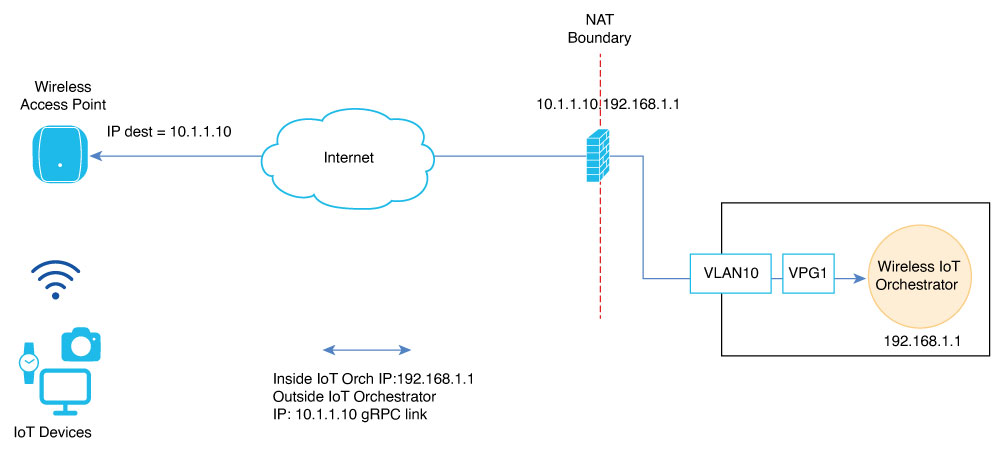
Figure 1. Schema for NAT configured external to the Cisco Catalyst 9800 Wireless Controller (Example: In a perimetral firewall)

In Figure 1, the external network device (for instance, a perimetral firewall or router) performs NAT or PAT for Sensor Connect.

Therefore, add the corresponding NAT IP address of Sensor Connect to the NAT IP address field.

To add the corresponding NAT IP address for Sensor Connect, perform these steps:

  1. Log in to the Cisco Catalyst 9800 Wireless Controller Web UI.

  2. Navigate to Configuration > Services > IoT Services.

  3. Enter the NAT IP address.


    Note


    The NAT IP address determines the destination IP address used by Cisco APs for the GRPC connection.


  4. Click Enable IoT Services.

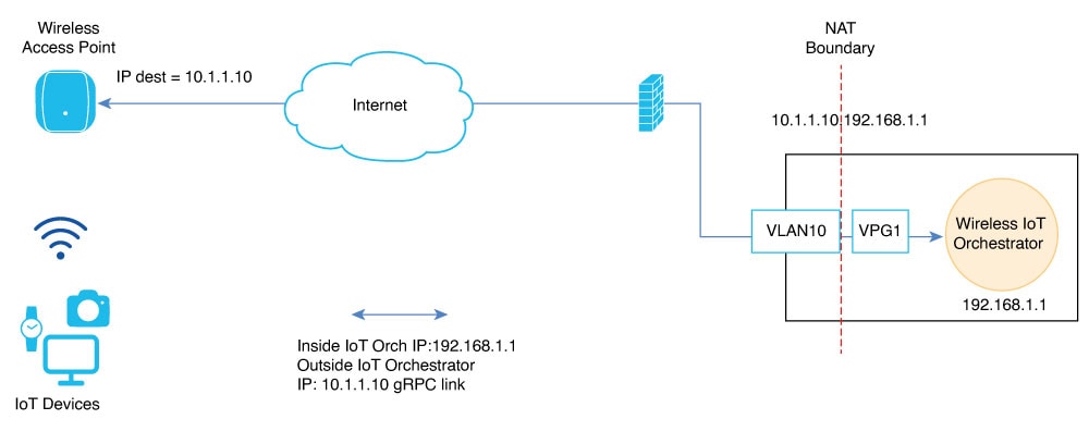
Figure 2. Schema for NAT configured on Cisco Catalyst 9800 Wireless Controller

Restrictions

  • Out-of-band management interfaces of the Cisco Catalyst 9800 Wireless Controller hardware appliances (interface configured under vrf Mgmt-intf) cannot be used as an outside interface for NAT.

  • The use of VRFs with NAT configuration for Sensor Connect is not supported.

  • Static and dynamic NAT or PAT are supported on all Layer 3 interfaces, including SVIs and physical interfaces configured with the no switchport command.

  • The IP address used as the global address must be an IP address of an interface on Sensor Connect. For more information, refer to CSCwn12646.

  • As a best practice, NAT should not be used on the same physical port as the Wireless Management Interface (WMI) when APs are deployed in large-scale local mode, or when the uplink port of the Cisco Catalyst 9800 Wireless Controller has limited bandwidth.

  • When APs are deployed in FlexConnect mode, there is no restriction on the NAT interface being the same as the WMI. For more information on the AP mode deployments, refer to the Catalyst 9800 Wireless Controller Configuration Model.

    Once the NAT is configured on the Cisco Catalyst 9800 Wireless Controller, the IP address selected as the NAT outside IP address of Sensor Connect must be configured in the NAT IP Address field as shown in Figure 2.

Review and accept the automatically generated NAT configuration

Ensure the generated NAT configuration matches your deployment requirements for Sensor Connect and connected APs.

During installation, the system generates a NAT configuration that controls connectivity between the Sensor Connect subnet, interface, default gateway, AP NAT interface, and default-gateway NAT interface.

Procedure


Step 1

Review the generated configuration, including the Sensor Connect private subnet, Sensor Connect interface and default gateway, AP NAT interface, default-gateway NAT interface, and corresponding NAT statements.

Step 2

Examine the discovered interfaces and configuration preview for accuracy.

Step 3

If the generated configuration is acceptable, accept it and continue the installation.

Step 4

If modifications are required, open the controller IoT Services page and click Edit.

Change the NAT interface selection or remove NAT, as required by your deployment.

Step 5

Validate that the selected interfaces provide reachability between the APs and Sensor Connect.

Step 6

Continue the installation and verify that the application status reaches Running.

Step 7

For APs that use an external NAT IP address, follow the Override AP NAT procedure as a special case.


The NAT configuration is fully validated and applied, enabling communication between APs and Sensor Connect according to your deployment requirements.

Examples of NAT Configuration on Cisco Catalyst 9800 Wireless Controller

Prerequisites

  • Before mapping any TCP port, ensure that it is not already in use by the Cisco Catalyst 9800 Wireless Controller. To verify, execute these commands to ensure that each port is available before you attempt to map it:

    
    Device# show tcp brief | include <tcp port>
    Device# show platform software tcpudpport | include <tcp port>
    

Configuration

These are the types of configurations:

  • Static NAT: Used for AP GRPC connections to Sensor Connect or for accessing the Sensor Connect GUI.

  • Dynamic NAT: Used when Sensor Connect requires an internet connection, leveraging one of the Cisco Catalyst 9800 Wireless Controller interfaces.

Example: Static NAT configuration

This example demonstrates how to expose ports 50221 and 43626 on a Cisco Catalyst 9800 Wireless Controller. The configuration was performed on a C9800-CL wireless controller running the 17.15.3 image. GigabitEthernet1 is configured as the Wireless Management Interface, and APs are deployed in FlexConnect mode.

Configuration details:
  • Sensor Connect IP address: 192.168.1.1/30

  • Default Gateway for Sensor Connect: 192.168.1.2

  • GigabitEthernet1 IP address: 10.1.1.10/24

To configure static NAT, issue these commands on the controller:


Device (config)# interface GigabitEthernet1
Device (config-if)# no switchport
Device (config-if)# ip address 10.1.1.10 255.255.255.0
Device (config-if)# ip nat outside
Device (config-if)# exit
Device (config-if)#interface VirtualPortGroup1
Device (config-if)# ip address 192.168.1.2 255.255.255.252
Device (config-if)# ip nat inside
Device (config-if)# exit
Device (config)# ip nat inside source static tcp 192.168.1.1 43626 interface GigabitEthernet1 43626
Device (config)# ip nat inside source static tcp 192.168.1.1 50221 interface GigabitEthernet1 50221
Device (config)# exit

To verify the static NAT configuration details, use this command:


Device# show platform software nat chassis active F0 translation
Pro  Inside global         Inside local          Outside local         Outside global
tcp  10.1.1.10:43626       192.168.1.1:43626     ---                   ---
tcp  10.1.1.10:50221       192.168.1.1:50221      ---                   ---
Total number of translations: 2

Example: Dynamic NAT configuration

This example demonstrates how to overload all traffic from Sensor Connect towards the internet through interface Vlan 180, except for traffic destined for access points. Assume an AP deployment in local mode, adhering to all NAT restrictions and recommendations in this document.

Configuration details:
  • Sensor Connect IP address: 192.168.1.1/30

  • Default Gateway for Sensor Connect: 192.168.1.2

  • Vlan 180 IP address: 172.16.200.100/24

  • IP subnets for access points: 192.168.15.0/24 and 10.10.10.0/24

To configure dynamic NAT, issue these commands on the controller:


Device(config)# interface Vlan 180
Device (config-if)# ip address 172.16.200.100 255.255.255.0
Device (config-if)# ip nat outside
Device (config-if)# exit
Device (config-if)#interface VirtualPortGroup1
Device (config-if)# ip address 192.168.1.2 255.255.255.252
	WLC(config-if)# ip nat inside
Device (config-if)# exit
Device (config)# ip access-list extended NAT_IOT_ACL
Device (config-ext-nacl)# 10 deny ip host 192.168.1.1 192.168.15.0 0.0.0.255
Device (config-ext-nacl)# 20 deny ip host 192.168.1.1 10.10.10.0 0.0.0.255
Device (config-ext-nacl)# 30 permit ip host 192.168.1.1 any
Device (config)# exit
Device (config)# ip nat inside source list NAT_IOT_ACL interface Vlan 180 overload
Device (config)# exit

To verify the dynamic NAT configuration details, use this command:


Device# show platform software nat chassis active F0 translation
Pro  Inside global         Inside local          Outside local         Outside global
icmp 172.18.29.7:8743      192.168.1.1:8743      8.8.8.8:8743          8.8.8.8:8743
tcp  172.18.29.7:5062      192.168.1.1:45156     173.37.145.84:443     173.37.145.84:443
Total number of translations: 2