The documentation set for this product strives to use bias-free language. For the purposes of this documentation set, bias-free is defined as language that does not imply discrimination based on age, disability, gender, racial identity, ethnic identity, sexual orientation, socioeconomic status, and intersectionality. Exceptions may be present in the documentation due to language that is hardcoded in the user interfaces of the product software, language used based on RFP documentation, or language that is used by a referenced third-party product. Learn more about how Cisco is using Inclusive Language.
This chapter describes the mesh deployment modes and contains the following sections:
Wireless Mesh Network
In a Cisco wireless outdoor
mesh network, multiple mesh access points comprise a network that provides
secure, scalable outdoor wireless LAN.
The three RAPs are connected
to the wired network at each location and are located on the building roof. All
the downstream access points operate as MAPs and communicate using wireless
links (not shown).
Both MAPs and RAPs can
provide WLAN client access; however, the location of RAPs are often not
suitable for providing client access. All the three access points in are
located on the building roofs and are functioning as RAPs. These RAPs are
connected to the network at each location.
Some of the buildings have
onsite controllers to terminate CAPWAP sessions from the mesh access points but
it is not a mandatory requirement because CAPWAP sessions can be back hauled to
a controller over a wide-area network (WAN).
Note
CAPWAP over CAPWAP
is not supported. AP in local mode connected on the RAP or MAP ethernet port is
not a supported configuration.
Wireless Backhaul
In a Cisco wireless backhaul network, traffic can be
bridged between MAPs and RAPs. This traffic can be from wired devices that are
being bridged by the wireless mesh or CAPWAP traffic from the mesh access
points. This traffic is always AES encrypted when it crosses a wireless mesh
link such as a wireless backhaul.
AES encryption is established
as part of the mesh access point neighbor relationship with other mesh access
points. The encryption keys used between mesh access points are derived during
the EAP authentication process.
Universal Access
You can configure the backhaul on mesh access points to
accept client traffic over its 802.11a radio. This feature is identified as
Backhaul Client Access in the controller GUI (Monitor > Wireless). When this
feature is disabled, backhaul traffic is transmitted only over the 802.11a or
802.11a/n radio and client association is allowed only over the 802.11b/g or
802.11b/g/n radio. For more information about the configuration, see the
“Configuring
Advanced Features” section on page 159.
Note
In rel 8.2 and higher the backhaul is also supported on 2.4 GHz.
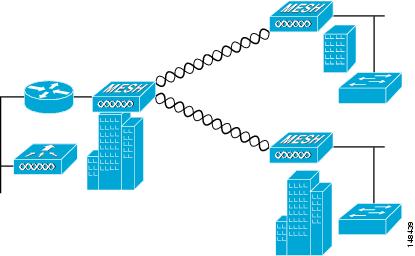
Point-to-Multipoint Wireless Bridging
In the
point-to-multipoint bridging scenario, a RAP acting as a root bridge connects
multiple MAPs as non-root bridges with their associated wired LANs. By default,
this feature is disabled for all MAPs. If Ethernet bridging is used, you must
enable it on the controller for the respective MAP and for the RAP.
Figure 1. Point-to-Multipoint Bridging
Example. This figure shows
a simple deployment with one RAP and two MAPs, but this configuration is
fundamentally a wireless mesh with no WLAN clients. Client access can still be
provided with Ethernet bridging enabled, although if bridging between
buildings, MAP coverage from a high rooftop might not be suitable for client
access.
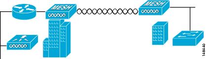
Point-to-Point Wireless Bridging
In a point-to-point
bridging scenario, a 1500 Series Mesh AP can be used to extend a remote network
by using the backhaul radio to bridge two segments of a switched network. This
is fundamentally a wireless mesh network with one MAP and no WLAN clients. Just
as in point-to-multipoint networks, client access can still be provided with
Ethernet bridging enabled, although if bridging between buildings, MAP coverage
from a high rooftop might not be suitable for client access.
If you intend to use an
Ethernet bridged application, we recommend that you enable the bridging feature
on the RAP and on all MAPs in that segment. You must verify that any attached
switches to the Ethernet ports of your MAPs are not using VLAN Trunking
Protocol (VTP). VTP can reconfigure the trunked VLANs across your mesh and
possibly cause a loss in connection for your RAP to its primary WLC. An
incorrect configuration can take down your mesh deployment.
Figure 2. Point-to-Point Bridging
Example
For security reasons the
Ethernet port on the MAPs is disabled by default. It can be enabled only by
configuring Ethernet bridging on the Root and the respective MAPs. To enable
Ethernet bridging using the controller GUI, choose
Wireless > All APs > Details for the
AP page, click the
Mesh tab, and then select the
Ethernet
Bridging check box.
Note
The overall
throughput of backhaul radio decreases by half for each hop of a mesh tree.
When the Ethernet-bridged clients are used in MAPs and heavy traffic is passed,
it may result in a high throughput consumption, which may cause the downlink
MAPs to disassociate from the network due to throughput starvation.
Ethernet bridging has to be
enabled for the following two scenarios:
When you want to use the mesh
nodes as bridges.
When you want to connect
Ethernet devices such as a video camera on the MAP using its Ethernet port.
Ensure that you enable
Ethernet bridging for every parent mesh AP taking the path from the mesh AP in
question to the controller. For example, if you enable Ethernet bridging on
MAP2 in Hop 2, then you must also enable Ethernet bridging on MAP1 (parent
MAP), and on the RAP connecting to the controller.
To configure range parameters
for longer links, choose
Wireless > Mesh. Optimum distance (in feet)
should exist between the root access point (RAP) and the farthest mesh access
point (MAP). Range from the RAP bridge to the MAP bridge has to be mentioned in
feet.
The following global
parameter applies to all mesh access points when they join the controller and
all existing mesh access points in the network:
Range: 150 to 132,000 feet
Configuring Mesh Range (CLI)
Procedure
To configure the distance
between the nodes doing the bridging, enter the
config mesh range command.
APs reboot after
you specify the range.
Note
To estimate the range and the
AP density, you can use range calculators that are available at:
To view the mesh
range, enter the
show mesh config command.
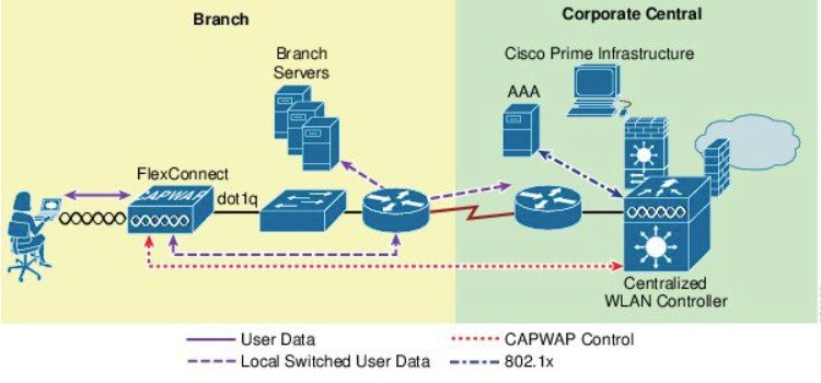
Introduction to Flex+Mesh in release 8.8
Below is a general
FlexMesh architecture. The CAPWAP AP is in Flex connect + Bridge mode with a
wired uplink to the core network in a 'Root' AP or RAP mode. The AP is still
managed by a centralized controller over CAPWAP. The AP however is capable of
moving to a standalone mode where the AP will be able to continue to serve the
802.11 clients depending on the data switching method of the WLAN configured on
the AP. The data can be centrally or locally switched. When data is centrally
switched, all data is sent to the WLC that does the switching further. In a
local switch network, the data is sent to RAP where RAP switches locally on the
wired uplink. There is no difference to the central and local switched WLAN
configurations and functionality between a Flex-Connect and Flex+Mesh mode AP.
Mesh COS AP that support new 8.8 Feature
1562 supported mesh
in 8.4 release. 1542 AP (1542D and 1542I) models supported Mesh in 8.5 release.
All these Aps should be able to support Flex Mesh as Flex Mesh designed on 1542
should be applicable to 1562 as well since Flex Mesh is a platform independent
feature.
Flex Mesh feature is supported on the IOS based Mesh AP even prior to release 8.8; however in rel 8.8 this feature is officially
supported on the COS based Mesh AP and supported by TAC starting with rel 8.8. In addition, the IPv6 is now supported on the
COS based Mesh APs.
There are two new
SKUs of 1542 that are developed. The AP1540 Series released in 8.5 meets most
of the technical requirement, but does not have external antennas. AP1542E2 and
AP1542E4 are hardware variants of 1541D/I AP. The 1542E2 is a dual band mode AP
with dual-radio dual-band 2.4GHz (802.11b/g/n, 20MHz) & 5 GHz
(802.11a/n/acW2, 20/40/80 MHz). The 1542E4 is a single band mode AP with
antenna A and B to support 2.4G and C and D to support 5G. The Aps support
minimum 2 TX & 2 RX chains, 2 spatial streams. AP expected to support
minimum 22 dBm (2.4 GHz) and 24 dBm (5 GHz) conducted transmit output power per
TX. Basic new PID additions and power table changes for this new platform will
be done on both AP and WLC. New power tables for -D(INDIA) with external
antennas.
Flexible Antenna
port configuration
The above HW changes have
requirements for SW changes as well. The AP needs to support a flexible antenna
port configuration. SW changes are done to let the user configure the antennas
to support either in a single band mode or dual band mode. Software
configurable Single Band Vs Dual Band mode. This is similar to the 1532 AP
configuration. The user can configure the antenna band modes using WLC CLI or
GUI.
Flex Mesh AP Running
Modes
Flex mesh COS AP can be running in
connected or standalone mode. Standalone mode in flex connect will undergo some
changes to inherit standalone functionality for a mesh network. There is also
another mode called 'abandoned' mode discussed below in this section of the
guide.
Connected Mode
A COS Flex Mesh AP (Root AP or Child
Mesh AP) is considered to be in connected mode when it can access and join the
WLC and can exchange periodic keep alive messages with WLC. In this mode, Flex
Mesh AP will be able support locally and centrally switched WLAN's. It shall
allow regular client and Child mesh APs to join.
Standalone Mode
A COS Flex Mesh AP, is considered to
be in standalone mode if it loses connection to the controller but it can
access the local gateway. In this mode, the COS Flex+Mesh AP will disable all
the centrally switched WLANs, and shall keep the locally switched WLANs up and
running. It will also allow the new clients to join on local switched WLANs
using local authentication as long as the authentication server is reachable in
the local network. Child mesh APs will NOT be allowed to join in this mode.
Abandoned Mode or
Persistent SSID Mode
A COS Flex+Mesh AP is in abandoned
mode when it can no longer access the gateway IP and has no connectivity to the
local network. Possible scenarios are:
AP is still not locked on to any
uplink wired or wireless.
A wireless uplink has been established but has not been
authenticated.
An uplink is established and authenticated, but IP address has the
gateway IP has not been configured.
An uplink is established, authenticated and also IP address and
gateway IP has been configured, but the gateway is not reachable for over a
minute.
Neither Child Mesh APs nor the clients are allowed to join in this
mode. Local as well as centrally switched WLANs will be disabled. AP may still
be scanning for an uplink in this mode so no beacons will be transmitted during
this time.
Note
For flex mesh COS APs, in abandoned mode, reboot timer shall be
enabled so the AP will have rebooted after 40 minutes, if it does not
transition to either standalone mode or connected mode.
Mode/State
transitions in the Flex Mesh COS APs
Flex Mesh mode COS AP will
always boot up in abandoned mode, in which it would need to scan for the uplink
(wired or radio).
Once a new uplink is selected either during initial stage or during
inter gateway roaming scenario, it is expected that the authentication should
pass and the CAPWAP connection needs to be formed within 2 minutes, else the
selected parent will be blacklisted. This function should be same as a regular
Mesh mode COS AP.
If a Flex mesh AP has a valid CAPWAP connection and it loses the
CAPWAP connection it will transition to standalone mode, and will stay in
standalone mode, as long as the gateway is reachable. A Flex Mesh AP will keep
track of the IP mode (IPV6 or IPV4) used for the last successful CAPWAP
connection and with track the reachability of the GW for that IP mode.
For Flex mesh AP in standalone mode, Mesh control will start a
timer (20 second) to periodically refresh the ARP entry for GW IP (IPV4 or
IPV6) and to also query the GW reachability status from the Path Control
Protocol. PCP will maintain the gateway reachability status from that AP either
reported by the Root AP via PCP messages or if it is Root AP by doing an ARP
lookup for the gateway IP address. If the GW is unreachable for over a minute,
the Flex Mesh AP will blacklist the parent and will transition to abandoned
mode and will re-scan for a new uplink.
To come out of the abandoned mode, AP must connect to the WLC and
transition to the connected mode. Transition from abandoned mode directly to
standalone mode is not supported and needs to be considered in future design
enhancements.
Design
considerations for Flex AP in standalone mode:
When the Flex AP is in
standalone mode, it will stick to the same parent and will NOT try to discover
or roam to a better neighbor, even if it is a preferred parent. The reason is
that there is no guarantee that the security will pass with the new parent and
the roaming will be successful. If the security fails, the perspective parent
may get blacklisted unnecessarily. It is best to consider standalone roaming
once standalone security is supported for Mesh APs in future design
enhancements.
BGN timer will be stopped in standalone mode. So, if the child mesh
AP is in standalone mode and it joins a parent with a different BGN and goes
back into standalone mode after that, BGN timer will be stopped so that the
child Mesh AP does not go into re-scan mode after 15 minutes (BGN timer
expiry).
In standalone mode, reboot timer will be stopped so that the AP
does not reboot after 40 minutes, in the absence of a CAPWAP connection.
After moving back to connected mode, from standalone mode, best
neighbor selection timer and BGN timer will be restarted, so allow the child
mesh AP to roam to the best possible neighbor.
Special standalone
mode for COS Flex RAPs
In this mode the SSID will be
broadcasted always (Persistent SSID). In addition, after reboot, when this
special Persistent mode is enabled, Flex Mesh RAP should be able to start
broadcasting the SSID even if the gateway is not reachable.
Existing
Flex-connect AP mode design
Locally switched WLANs are stored in config.flex file and
Flex-connect AP broadcasts the local WLAN SSIDs as long as it is standalone
mode.
On boot up Flex-connect AP would only start broadcasting the
locally switched WLANs if the gateway provisioned.
If for a COS Flex connect AP, gateway information is removed at
some point, it moves out of the standalone mode and stops broadcasting the
locally switched SSIDs and waits for gateway to be provisioned again.
Once the gateway is provisioned, Flex AP again transitions into the
standalone mode and starts broadcasting the locally switched SSIDs again.
Without a valid gateway, flex-connect AP eventually stops
broadcasting SSIDs, since the local network is not reachable so no reason to
connect the clients.
Parts of the existing Flex-connect AP mode design is used to retain
WLAN configuration during reboot and to be able to start broadcasting Local
SSIDs etc. However, for Flex RAP we have a special standalone mode requirement
for NBN deployment as stated below:
Flex RAP should be able to boot up directly into the standalone
mode and start broadcasting SSIDs, even if the gateway is not reachable.
Flex RAP will continue to be in standalone mode and keep
broadcasting SSIDs if the gateway was reachable earlier and becomes unreachable
at some point.
Even if the Flex RAP cannot support any real clients, it still
needs to broadcast SSID so that the operator can check if the AP is UP and
running.
Design
considerations to support new requirement
Flex RAP should join the
controller at least once to download the WLAN configuration that gets stored in
the config.flex file. This WLAN is a local switched one.
Once the configuration is stored in the config.flex file, it will
become persistent across the reboots and AP does not need to join WLC again as
long as the configuration is not erased.
A new configuration that is needed for the RAP to maintain the
wired link is supported and will be stored in mesh configuration file i.e.
"strict_wired_uplink".
If the following conditions are true, FLEX Mesh AP will broadcast
the local WLANs stored in flex configuration file even if the gateway is not
reachable.
AP is a Flex Mesh Root AP
AP is configured with strict_wired_uplink as true.
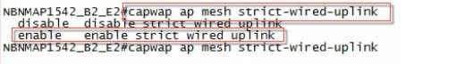
A new AP CLI command will be supported to configure a Flex Mesh AP
as a strict wired AP.
# CAPWAP ap mesh strict-wired-uplink <true/false>
New configuration parameter "strict_wired_uplink" will be stored in
config.mesh file in storage directory so that it is persistent across the
reboots. Default value of this parameter will be false.
Strict wired uplink configuration is only valid if the AP is
configured as Flex-Mesh Root AP. For all other AP modes and for Mesh AP role,
strict wired uplink configuration will not be effective, even if configured.
When strict wired uplink is true for Flex Mesh Root AP:
Wired uplink will be immediately selected on mesh restart.
Wired uplink will never be blacklisted
CAPWAP up timer will not run
Mesh Reboot timer will not run
Seek of the wired adjacency will always return true, even if the
interface is down
Wireless backhaul can never be selected as an uplink
Wireless backhaul can still be used as downlink to provide
connectivity to the Mesh child nodes
To avoid issues due to gateway configuration checks, static IP and
gateway must be configured on the Flex RAP (even if it just a dummy IP or
gateway).
Having Static IP and Gateway configuration will allow the Flex
RAP to transition into standalone mode after reboot even when there is no
connectivity to the local network (i.e. no DHCP server to provision IP and
gateway). Flex RAP will then continue broadcasting the locally switched SSIDs
even in absence of any network connectivity.
If the IP and gateway are not valid, and once AP has
connectivity to DHCP server, DHCP IP overwrites the static IP configuration and
DHCP IP and gateway configuration takes over.
A Simple WLC CLI to enable/disable the 'Persistent SSID' feature
will be provided. The WLC and AP should have communication for this
configuration to take effect.
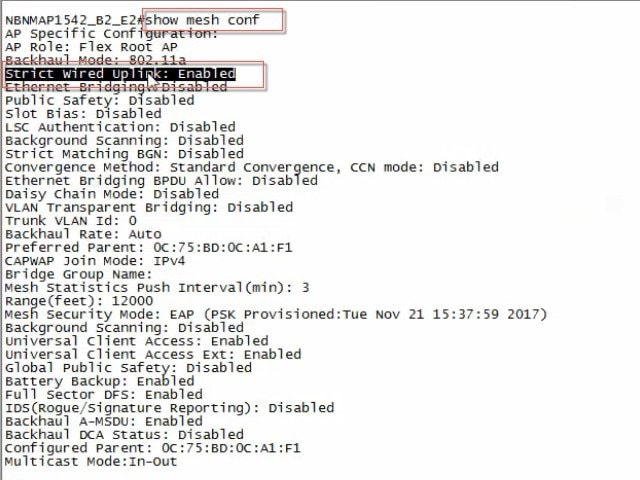
The AP 'show mesh config' will also dump the current status of this
feature.
Configuring Mesh
Enhancements
Procedure
Step 1
As indicated in
the explanation above the RAP has to be configured to be in an Persistent
Transmit of the SSI mode. This configuration option is available from the CLI
mode only.
Step 2
To verify that
the mode is enabled execute a "show mesh config" command and the "strict wired
uplink" should show as Enabled.
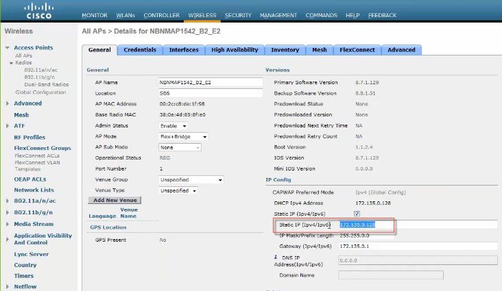
Step 3
As indicated
above for the persistent SSID to function and to avoid issues due to gateway
configuration checks, static IP and gateway must be configured on the Flex RAP
(even if it just a dummy IP or gateway). Having Static IP and Gateway
configuration will allow the Flex RAP to transition into standalone mode after
reboot even when there is no connectivity to the local network (i.e. no DHCP
server to provision IP and gateway). Flex RAP will then continue broadcasting
the locally switched SSIDs even in absence of any network connectivity.
If the IP and
gateway are not valid, and once AP has connectivity to DHCP server, DHCP IP
overwrites the static IP configuration and DHCP IP and gateway configuration
takes over.
Steps for testing RAP Persistent Mode in Rel 8.8
In order to test the setup best is
to configure one RAP with perrsistant SSID or in abandoned mode and one in a
regular RAP mode. Connect a client to both RAP and observe behavior when RAPs
lose their connectivity to the controller.
Client with Persistent Mode
enabled should maintain connectivity to the RAP, since RAP continues to
transmit the SSID.
Client that connected to the regularly configured RAP will lose
connectivity since SSID will stop being transmitted.
Introduction to Additional Mesh Features in release 8.8
This section of the deployment guide introduces the few new Mesh or Outdoor AP features in the release 8.8.
The purpose of this document is to provide configuration guidance of the following features:
“Lawful Intercept (LI)” and Monitoring
Whitelisting of specific URLs
Captive Portal Configuration
Policy Enforcement and Quota Management
“Lawful Intercept” (LI) and Monitoring in Rel 8.8
Certain Cisco customers have plans to deploy Cisco Wifi Mesh solution across very large geographical areas with a Flex+Mesh
(with local switching) tree. A RAP (Root Access Point) with a wired backhaul to the centralized WLC shall forms a mesh tree
serving wireless clients. Lawful Intercept feature is a process of lawful interception and monitoring of mobile phones, landlines,
and wireless internet traffic if administration decides to set up a Centralized Monitoring System (CMS) .
There will be a mesh network in Flex+Mesh mode setup and as part of LI, export the client flow information for each flow will
be provided.
RAP will do the NAT/PAT as well as LI record generation and sending to LI server via WLC. For all flows, a record will be
created in the NAT/PAT. At that point, RAP will create the Syslog record for that flow. RAP will send those Syslog packets
through CAPWAP-DATA to the WLC.
Note
Any peer to peer client traffic within mesh tree which does not go via RAP (only MAP handles locally) will not be considered
to be reported to LI server.
WLC will update the syslog packet with its own MAC and IP and will forward the Syslog packets to the Syslog server in the
network. These packets will not be encrypted.
This will be the typical workflow:
Admin has to configure Syslog server config.
Either IPv4 or IPv6 is only supported.
If IPv6 is configured then WLC should be IPv6 enabled.
The existing “config ap syslog global “ command will be functional.
LI will be enabled/disabled only Globally.
Prerequisite for this will be Syslog server config.
AP saves the syslog server configuration (IP address and enable/disable) received from WLC on RAP.
IPv4 packets to be NAT/PAT(in case of internal DHCP) on the packets.
IPv6 packets and also IPv4 packets (in case of external DHCP) will:
Identify flows based on packet Source/dest IP/port.
Save the flows in a FlowTable entry.
LI Reporter element will:
Receive and save new flow records pushed by NAT element/FlowTable element.
It will run a periodic timer (typically 1 minute).
c. On expiry of this timer, all the flow records in its table are flushed and converted to syslog records containing both
v4 and v6 flows together. Syslog format is given in next section.
Only at the beginning of the flow creation, it will be sent. Subsequently, no other flow records will be sent.
AP will form the syslog packet
8) WLC will recognize whether it is LI packet or not.
Update the contents,
IP: Dst IP: LI IP (v4 or v6)
Source IP: Mgmt IP
Dst Mac: GW Mac
Source Mac: Mgmt Mac
UDP Source Port: 514
UDP Dest Port: 514
Based on the Inner IP packet, WLC will update the Mgmt IP.
If it is IPv4 then Mgmt IP will be updated.
If it is IPv6 then Mgmt IPv6 will be updated
WLC will not store any records.
Stats will be recorded for the incoming messages from AP.
Stats will also be recorded for the outgoing messages from WLC to syslog server.
Also, other stats if the packet is dropped.
Whenever show command is executed it will show the log.
Syslog Format for Netflow Collector
The syslog record is then encapsulated inside UDP/IP header from AP to LI server based on the config received from WLC.
A Syslog record will be formatted as below:
“syslog header+’:’+ LI Header +’:’+ LI Record 1+’|’+ LI Record 2 +’|’+….”
Syslog Header
Facility: Syslog facility code.
Severity: Syslog Severity.
Timestamp: Time at which the AP sends out the syslog message. This is sent in human readable date format : mmm dd yyyy hh:mm:ss
Hostname: Name of the AP (RAP Name)
Tag: The Tag field is a string that signifies what type of message is carried in the payload. (AP_LI_V4_FLOW/ AP_LI_V6_FLOW)
LI Header:
“VVTTTTTTTTMMMMMMMMMMMM”
VV: Version, currently it is always “01”
TTTTTTTT: Time in seconds when this logging is created, Hex values
Pre-requisite: Ap Syslog should be configured else it will not allow.
Existing command is modified to reflect LI changes.
# config ap syslog host global <ipv4/ipv6>
Pre-requisite: If IPv6 is trying to configure we need to check whether IPv6 is enabled and Management is configured with IPv6 address.
There is a new show command to show the stats.
(Cisco Controller) >show flexconnect lawful-interception ?
summary        Display Lawful-Interception summary.
Example of the LI show command on the controller:
(Cisco Controller) >show flexconnect lawful-interception sum
Lawful Interception Status: Disabled
Lawful Interception Timer: 60
Lawful Interception IPv4 Addr: 192.201.1.1
Lawful Interception IPv6 Addr: Not Configured
Note
There will be show commands on AP to display the configured LI server IP and status.
Example of the show LI command on the AP.
AP-2802#show lawful-intercept
Enable: false
Interval(sec): 60
AP IPv4 Address: 1.5.39.108
AP IPv6 Address: ::
Max records: 15
syslog src ip: 192.201.1.2
syslog src ipv6: ::syslog
src mac: 00:01:02:03:04:09
extlog server ip: 0.0.0.0
extlog server ipv6: ::
extlog server mac: 00:8E:73:56:24:C7
ap name: AP-2802
GUI Configuration of LI
To configure Lawful Intercept from the Controller GUI interface follow the steps below:
Procedure
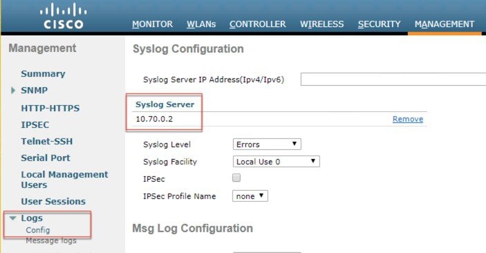
Step 1
On the controller Management tab configure Logs>Config the IP address of the Log Server.
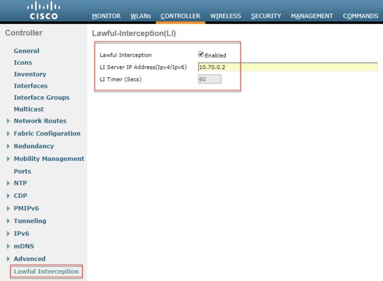
Step 2
On the Controller tab choose Lawful Intercept and then enable it with the Log Server IP address configured. Hit Apply.
Whitelisting of specific URLs in Rel 8.8
The feature of Whitelist specific URLs on the controller / AP so that users can access those specific sites without having
connectivity to the internet. No authentication is mandated to access the whitelisted URLs.
Customer device associates to “XXXX” SSID
A client gets the IP address and moves to "webauth" required state for HTTP and HTTPS sites
A client is able to access the whitelist websites even without authentication; for example, Providing location specific information
and other details to the user
Unique whitelist URL (based on flex group) for specific GP's based on the local rural policy
When the user attempts to navigate to other websites not configured in the whitelist walled garden profile, the user is redirected
back to the login page.
Once a user is authenticated, he has access to the internet (non-whitelist websites)
Above feature was addressed with DNS-PreAuth ACL feature implemented in 8.7 release (DNS-ACL). A max of 20 domain names can
be configured and snooped IP addresses (max 64) will be sent to WLC to assist client roam across APs in webauth_reqd state.
Clients shall use these URLs without any authentication as data traffic to/from the snooped IPs (of preconfigured URLs) are
allowed from AP.
As https encrypted packets do not give clear-text URL name to allow/deny access in client’s webauth_reqd state, IP address
snooping is required to address this requirement.
Admin has to configure a preAuth ACL with a list of whitelisted URLs and map it to a FlexConnect Group assigned to a specific
location or users.
This feature is to allow users to have multiple splash pages per SSID (Flex group/VLAN based). When users at specific locations
are segregated based on VLANs however, in the same SSID (XXXX) will be broadcasted by the WLAN hence need the feature which
can support multiple splash pages on single SSID.
Use-case :
Customer device associates to “XXXX” SSID
A client gets the IP address and moves to "webauth" required state for HTTP and HTTPS sites
Customized Captive Portal through external Web-auth is presented to the user based on the AP group configuration
Scaling is to be taken care of in this scenario. If there are many remote locations connected to one WLC and each location
will require its own captive portal. For example, WLC 8540 can support 6000 APs. One remote location can have have ~ 5-6 APs
so ~ 1000 locations can be connected to one WLC8540 hence WLC will support 1000 splash pages in order to support one splash
page for each remote location.
Presently WLC supports external redirect-URL configuration per SSID. This new feature will allow multiple external re-direct
URLs for a single SSID, either FlexConnect group (OR) AP Group should be taking the configuration input of external re-direct
URL and apply to clients behind the APs mapped to the group.
Configured redirect-URL shall be listed in existing show dump:
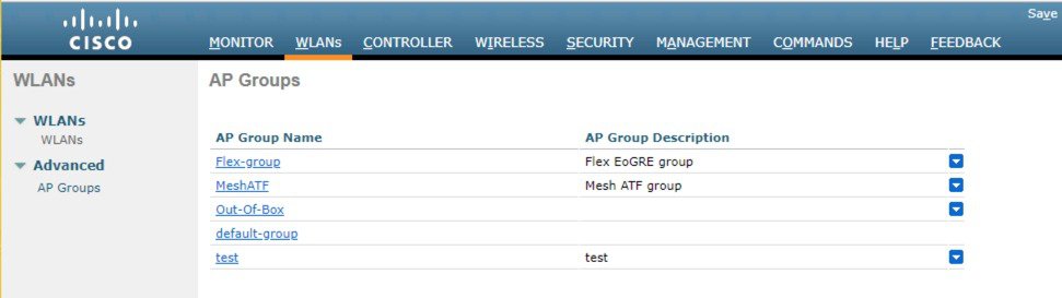
(WLC)show wlan apgroups
GUI Configuration of Captive Portal
To configure a captive portal from the controller GUI follow the steps below:
Procedure
Step 1
From the WLAN tab chose Advanced>AP Groups and then create a Flex Group and than select a Flex Connect group to apply the
Captive portal .
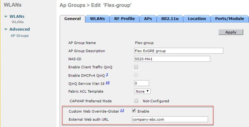
Step 2
Enable “custom web override” and enter the “External WebAuth URL”
Note
In this feature, you can create multiple groups with different Captive Portal per the same WLAN and overwrites External Webauth
URL configured at Global WLAN level.
Policy Enforcement and Quota Management in rel 8.8
For Quota management - WLC should accept the Radius user authorization change request to allocate different quota to the same
user without disconnecting the user.
This feature is supported in:
Local, Bridge (Central Switching)
Flexconnect, Flex+Bridge (Local Switching)
Feature Use-case:
A client has 2 GB plan to access the internet
AP is monitoring the bandwidth usage and reporting the statistics to the controller (Bandwidth monitoring)
The controller sends the Interim update to the radius server for IPv4 and/or IPv6 (Dual Stack clients)
As soon as the given Quota is exhausted, Radius sends CoA to change the policy to a different default plan - (CoA override)
A client gets moved to a new plan without actually being disconnected from the network – (Applying new policy on the fly)
Dynamic Policy from AAA
802.11 clients are allotted QoS policy and data rate limits on authenticating with AAA Server
WLC does not support ‘run-time' policy enforcement as the client gets new policies during full authentication
RFC-5176 allows dynamic rate limiting using Change-of-Authorization(CoA) request / response
End clients get provisioned with maximum allotted quota by Service providers based on prepaid / postpaid data plans
External billing servers notify AAA on reaching maximum data limit per client basis
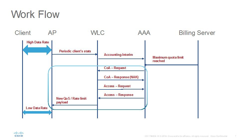
Feature Implementation on the WLC
In order to get the new policy/quota enforcement, following enhancements are implemented in WLC:
WLC periodically sends Accounting-Interim to AAA with client statistics.
On reaching the maximum quota allotted per client, AAA will send a CoA-Request with service-type set to “Authorize Only” along
with a state parameter.
WLC will respond with CoA-NAK with service-type set to “Authorize-Only” and with state parameter unmodified.
WLC will also send an Access-Request to AAA with service-type set to “Authorize-Only” along with state parameter as received
in CoA-Request.
Access-Request shall have the same format of holding other session attributes / NAS as received in CoA-Request.
AAA will respond with Access-Accept with the new policy on rate/bandwidth enforcement.
WLC will forward these new QoS parameters to AP using existing AP_AAA_QOS_PARAMS_PAYLOAD .
AP will apply the new QoS values to the flex local switched client.
There will not be any Disassociation / De-Authentication message sent from WLC or AP to the end client.
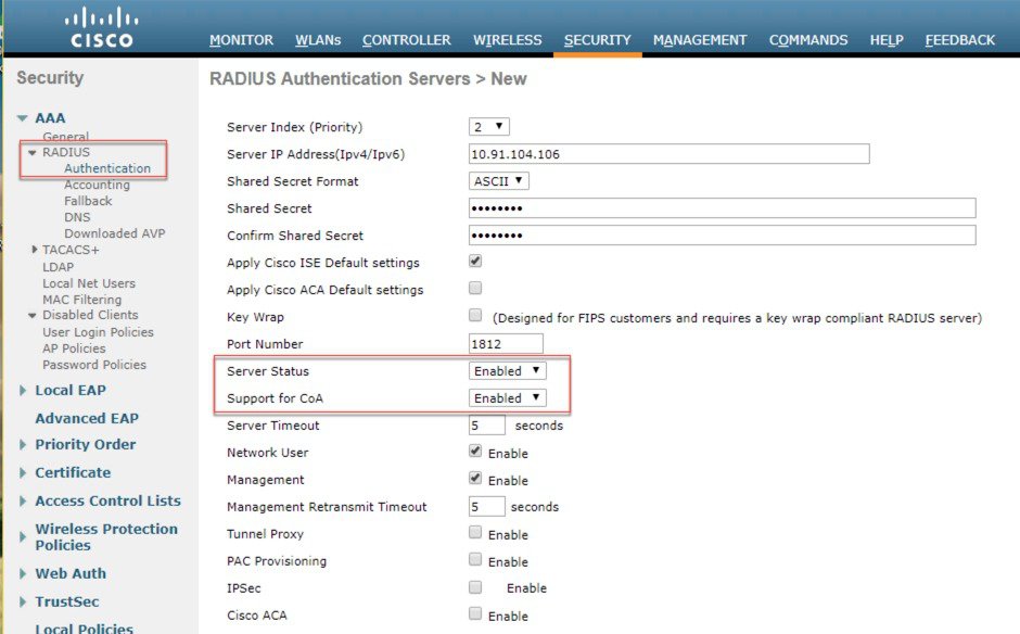
Configuration from GUI
Procedure
Step 1
Configure Authentication Server from Security>Radius>Authentication and select “Support for CoA” as shown in the example
below.
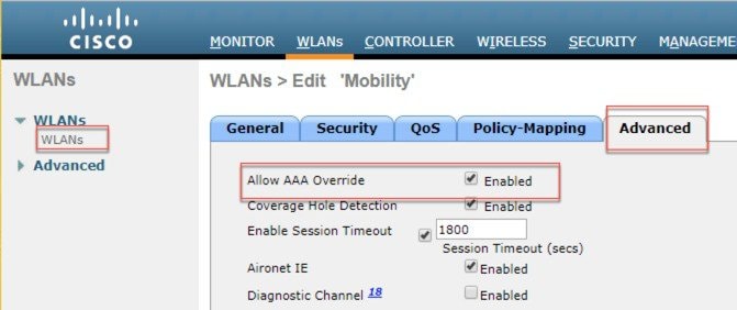
Step 2
On the WLAN choose the AAA override option as shown below.


 Feedback