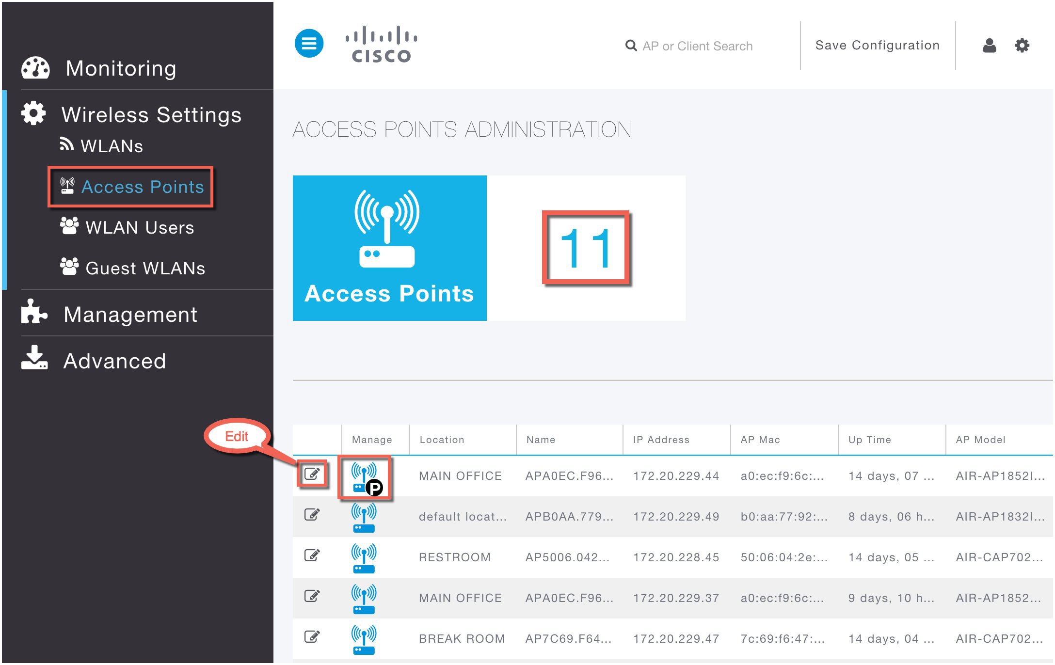
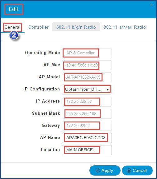
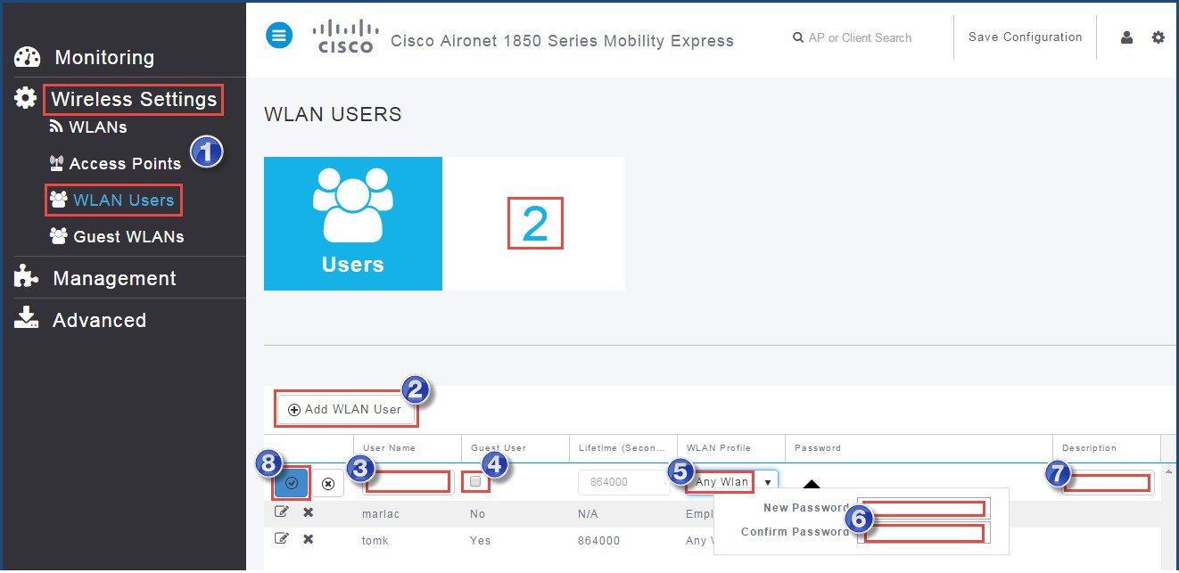
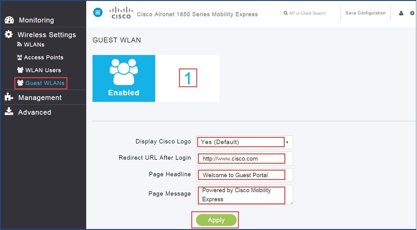
WLANs
The Cisco Mobility Express solution can control up to 16 WLANs for lightweight access points. Each WLAN has a WLAN ID (1 through 16), a Profile Name, a WLAN SSID, and can be assigned with unique security types.
 Note |
Management traffic is untagged and we recommend you to assign one VLAN for Management and another set of VLANs for client. |
Creating WLANs using GUI
To create a WLAN using GUI, perform the following steps:
Procedure
| Step 1 |
Choose . 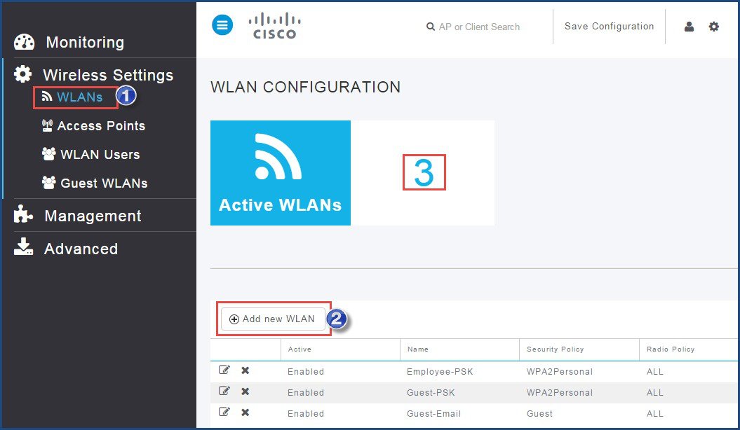 |
||||||||||||||||||||||||||
| Step 2 |
Click Add New WLAN. The Add New WLAN window appears. |
||||||||||||||||||||||||||
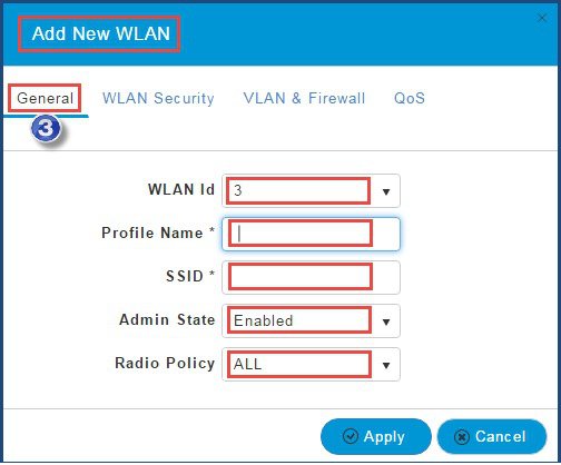
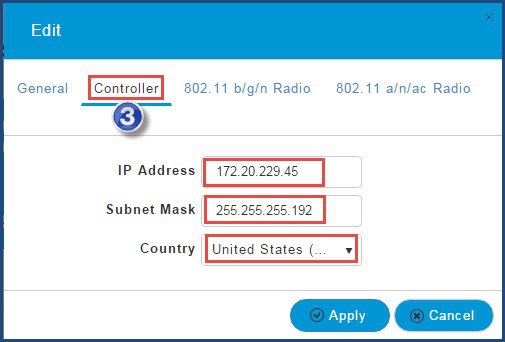
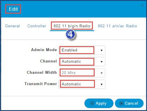
| Step 3 |
In the General tab, perform the following:
|
||||||||||||||||||||||||||
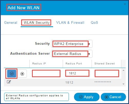
| Step 4 |
In the WLAN Security tab, perform the following: Choose the Security type from the drop-down list. The supported security types for WLAN are: The default Security is WPA2 Enterprise with Authentication Server as External Radius.
|
||||||||||||||||||||||||||
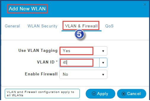
| Step 5 |
In the VLAN & Firewall tab, perform the following:
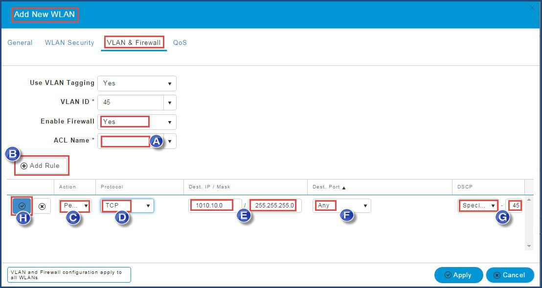
|
||||||||||||||||||||||||||
| Step 6 |
Click Apply to save ACL. |
||||||||||||||||||||||||||
| Step 7 |
In the QoS tab, perform the following: 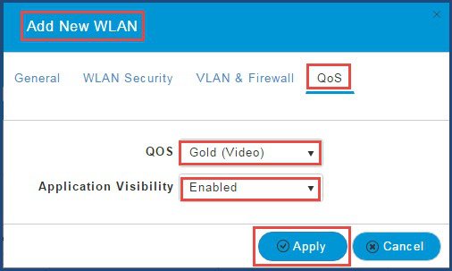 |
||||||||||||||||||||||||||
| Step 8 |
Click Apply. |


 Feedback