Getting Started

This chapter provides information about the Mobility Express ports, interfaces, WLANs, LED states and access switch configuration.

Ports

A port is a physical entity that is used to connect Cisco 1800 series access points to the network. The ports available on Cisco 1800 Access Points are as shown.
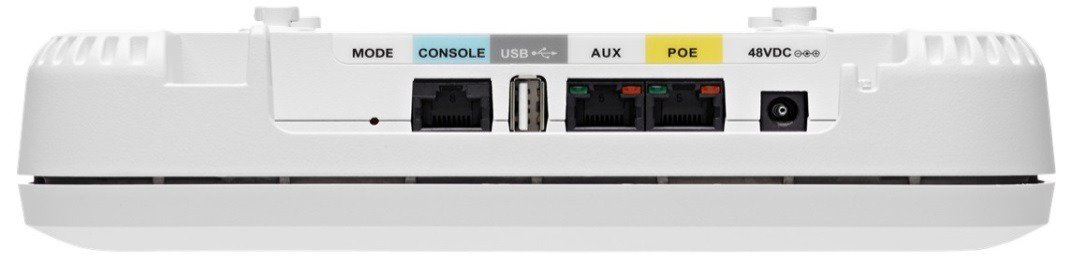
Figure 1. Ports of Cisco 1800 series Access Points

Mode

The Mode button is used to reset the Access Point to factory defaults. T o reset, depress the button and connect power to the AP. Hold the button depressed for 20s and then release it. When the button is released, the following message will be seen in the console. The AP will reboot and will be reset to factory defaults. If the AP has the Mobility Express controller image, after the reboot, it will broadcast the CiscoAirProvision SSID.


Console Port (RJ-45)

The Cisco 1800 series has one console port. It provides console access to the Mobility Express controller CLI.

USB

This port is not currently supported.

Aux Port (RJ-45)

This port is not currently supported.

POE (Management Port) (RJ-45)

The Cisco 1800 series Access Points has a port marked as POE. This port is used to provide Management access to the Mobility Express Controller.

Access Point Status LEDs

The location of the access point status LED is shown in Figure 1.


Note

The LEDs may show small variations in color intensity and hue from unit to unit. This variation is within the normal range of the LED manufacturer's specifications and is not a defect.


The access point status LED indicates various conditions such as:

Table 1. LED Status Indications

Message Type

LED Type

Meaning of Message

Client Association status

Chirping Green

Normal operating condition, but no wireless client associated.

Green

Normal operating condition, at least one wireless client association.

Boot loader status

Green

Executing boot loader

Boot loader error

Red

Boot loader signing verification failure.

Boot loader signing verification failure

Blinking Amber

AP priming to a new regulatory domain by Neighbor Discovery Protocol (NDP) is in progress.

Cycling Red, Green and off

AP waiting to be primed.

Chirping Red

AP primed to a wrong regulatory domain.

Operating status

Blinking amber

Software upgrade is in progress

Cycling through green, red and amber

Discovery/join process is in progress

Rapidly cycling through red, green, amber and off

Access point location command invoked from controller web interface.

Access point operating system

Cycling through red, green, amber, and off General warning, insufficient inline power.

Interfaces

An interface is a logical entity on Mobility Express. The management interface must be configured and is used for in-band management: Web GUI, Telnet/SSH CLI, SNMP.

WLANs

A WLAN associates Service Set Identifier (SSID) to VLANs. It is configured with Security type, Quality of Service (QoS), radio policies, and other wireless network parameters. On Mobility Express network, up to 16 WLANs can be configured. The WLANs can be mapped to VLANs trunked on the switch port.

Switch Configuration

All Access Points including the Primary AP in a Mobility Express network should be in the same L2 broadcast domain. Management traffic must not be tagged.

The switch to which the Access Points connects have configuration similar to the one shown below:

vlan 10
 name Employee
vlan 20
 name Guest
vlan 122
name Management

interface Vlan10
 description >> Employee Network << 
 ip address 10.10.10.1 255.255.255.0
!
interface Vlan20
 description >> Guest Network <<
 ip address 20.20.20.1 255.255.255.0
!
interface Vlan122
 description >> Management, Master AP and Subordinate APs<<
 ip address 172.20.229.2 255.255.255.0

interface GigabitEthernet1/0/37
 description >> Connected to Cisco 1850 Access Point <<
 switchport trunk native vlan 122
 switchport trunk allowed vlan 10,20,122