DHCP for WLANs

Dynamic Host Configuration Protocol

Dynamic Host Configuration Protocol (DHCP) is a network protocol that

  • dynamically assigns IP addresses to devices on a network for IP communication

  • enables configuration of WLANs to use the same or different DHCP servers or no DHCP server, and

  • provides two types of DHCP servers—internal and external.

Internal DHCP servers

An internal DHCP server is a device-based DHCP service that

  • provides DHCP addresses to wireless clients, direct-connect APs, and DHCP requests that are relayed from APs

  • supports only lightweight APs, and

  • requires SVI configuration for the client VLAN with the IP address set as DHCP server IP address.

General guidelines

The device contains an internal DHCP server. This server is typically used in branch offices that do not have a DHCP server.

A wireless network generally contains a maximum of 10 APs or less, with the APs on the same IP subnet as the device.

DHCP option 43 is not supported on the internal server. Therefore, the APs must use an alternative method to locate the management interface IP address of the device, such as local subnet broadcast, Domain Name System (DNS), or priming.

When clients use the internal DHCP server of the device, IP addresses are not preserved across reboots. As a result, multiple clients can be assigned to the same IP address. To resolve any IP address conflicts, clients must release their existing IP address and request a new one.

Wired guest clients are always on a Layer 2 network connected to a local or foreign device.

Key configuration requirements:

  • Internal DHCP server serves both wireless client and wired client (wired client includes AP).

  • To serve wireless client with internal DHCP server, an unicast DHCP server IP address must be configured for wireless client. Internal DHCP server IP address must be configured under the server facing interface, which can be loopback interface, SVI interface, or L3 physical interface.

  • To use internal DHCP server for both wireless and wired client VLAN, an IP address must be configured under client VLAN SVI interface.

  • For wireless client, in DHCP helper address configuration, the IP address of the internal DHCP server must be different from address of wireless client VLAN SVI interface.

  • For wireless client with internal DHCP server support, the internal DHCP server can be configured using global configuration command, under the client VLAN SVI interface or under the wireless policy profile.

  • An internal DHCP server pool can also serve clients of other controllers .


Note


  • VRF is not supported in the internal DHCP servers.

  • DHCPv6 is not supported in the internal DHCP servers.


External DHCP servers

An external DHCP server is a separate server outside the device that

  • dynamically assigns IP addresses within a network

  • operates with industry-standard DHCP Relay support, and

  • maintains client IP addresses during roaming scenarios.

External DHCP server operation

The operating system is designed to appear as a DHCP relay to the network and as a DHCP server to clients with industry-standard external DHCP servers that support DHCP Relay, which means that each controller appears as a DHCP relay agent to the DHCP server, and as a DHCP server in the virtual IP address to wireless clients.

Because the controller captures the client IP address that is obtained from a DHCP server, it maintains the same IP address for that client during intra controller, inter controller, and inter-subnet client roaming.


Note


External DHCP servers support DHCPv6.


DHCP assignments

A DHCP assignment is a network configuration method that

  • configures DHCP servers on a per-interface or per-WLAN basis,

  • allows assignment of primary and secondary DHCP servers to individual interfaces, and

  • enables DHCP server definition on WLANs to override interface-level DHCP server addresses.

DHCP assignment configuration

You can configure DHCP on a per-interface or per-WLAN basis. We recommend that you use the primary DHCP server address that is assigned to a particular interface.

You can assign DHCP servers for individual interfaces. You can configure the management interface, AP manager interface, and dynamic interface for a primary and secondary DHCP server, and configure the service-port interface to enable or disable DHCP servers. You can also define a DHCP server on a WLAN (in this case, the server overrides the DHCP server address on the interface assigned to the WLAN).

For enhanced security, we recommend that you ask all clients to obtain their IP addresses from a DHCP server. To enforce this requirement, you can configure all the WLANs with a DHCP Address. Assignment Required setting, which disallows client static IP addresses. If DHCP Address Assignment Required is selected, clients must obtain an IP address through DHCP. Any client with a static IP address is not allowed on the network. The controller monitors DHCP traffic because it acts as a DHCP proxy for the clients.


Note


  • WLANs that support management over wireless must allow management (device-servicing) clients to obtain an IP address from a DHCP server.

  • The operating system is designed to appear as a DHCP relay to the network and as a DHCP server to clients with industry-standard external DHCP servers that support DHCP relay. This means that each controller appears as a DHCP relay to the DHCP server and as a DHCP server at the virtual IP address to wireless clients.


You can create WLANs with DHCP Address Assignment Required disabled. If you do this, clients have the option of using a static IP address or obtaining an IP address from a designated DHCP server. However, note that this might compromise security.


Note


DHCP Address Assignment Required is not supported for wired guest LANs.


You can create separate WLANs with DHCP Address Assignment Required configured as disabled. This is applicable only if DHCP proxy is enabled for the controller. You must not define the primary or secondary configuration DHCP server instead you should disable the DHCP proxy. These WLANs drop all the DHCP requests and force clients to use a static IP address. These WLANs do not support management over wireless connections.
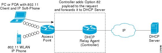
DHCP option 82

DHCP option 82 is a DHCP relay agent feature that

  • provides additional security when DHCP is used to allocate network addresses

  • enables the controller to act as a DHCP relay agent to prevent DHCP client requests from untrusted sources, and

  • allows the controller to add option 82 information to DHCP requests from clients before forwarding the requests to the DHCP server.

DHCP option 82 operation

The AP forwards all the DHCP requests from a client to the controller. The controller adds the DHCP option 82 payload and forwards the request to the DHCP server. The payload can contain the MAC address or the MAC address and SSID of the AP, depending on how you configure this option.


Note


DHCP packets that already include a relay agent option are dropped at the controller.


For DHCP option 82 to operate correctly, DHCP proxy must be enabled.

Figure 1. DHCP Option 82

Restrictions for configuring DHCP for WLANs

When configuring DHCP for WLANs, ensure proper server reachability and service enablement to avoid connectivity issues.

  • If you override the DHCP server in a WLAN, you must ensure that you configure the underlying Cisco IOS configuration to make sure that the DHCP server is reachable.

  • WLAN DHCP override works only if DHCP service is enabled on the controller.

    You can configure DHCP service in either of the following ways:

    • Configuring the DHCP pool on the controller.

    • Configuring a DHCP relay agent on the SVI. Note that the VLAN of the SVI must be mapped to the WLAN where DHCP override is configured.

Guidelines for DHCP relay configuration

Relay agent source IP

Configure the relay agent source IP according to the following precedence order to ensure proper DHCP relay functionality.

  • If you configure source interface VLAN in the SVI interface, the IP address of the VLAN interface configured as source is used.

  • If the Relay Agent source IP is not mentioned, the IP address of the SVI interface created for the corresponding client's VLAN is used.

  • If the Relay Agent source IP is not mentioned, the source address specified at the global level is used.

DHCP server

Configure DHCP server addresses according to the following precedence order to ensure proper server selection.

  • If the DHCP server address is configured in the wireless policy profile, the server address configured in the policy profile takes precedence.

  • If the DHCP server address is not configured in the policy profile, the server address configured in SVI takes precedence.


    Note


    You can configure two server addresses in the SVI. In this case, the DHCP packets from the client are sent to both the servers.

    The Option 82 configured in policy profile, SVI, and globally is considered and honored together.


These guidelines apply to central DHCP and local switching configurations. The DHCP packets are sourced from the IP address of the Wireless Management Interface (WMI), if VLAN is not configured in the policy profile and AAA override. The SVI interface configuration is mandatory to achieve the DHCP relay functionality in central DHCP or local switching. Even though many interface options are available in the ip dhcp relay source-interface <> command, only VLAN interface is applicable.

How to Configure DHCP for WLANs

Configure DHCP scopes (GUI)

Configure DHCP scopes to automatically assign IP addresses and network configuration parameters to wireless clients on your network.

DHCP scopes define the range of IP addresses available for assignment to clients, along with associated network configuration parameters such as subnet masks, default routers, and DNS servers.

Procedure


Step 1

Choose Administration > DHCP Pools.

Step 2

In the Pools section, click Add to add a new DHCP pool.

The Create DHCP Pool dialog box is displayed.

Step 3

In the DHCP Pool Name field, enter a name for the new DHCP pool.

Step 4

From the IP Type drop-down list, choose the IP address type.

Step 5

In the Network field, enter the network served by this DHCP scope.

This IP address is used by the management interface with netmask applied, as configured in the Interfaces window.

Step 6

In the Subnet Mask field, enter the subnet mask assigned to all the wireless clients.

Step 7

In the Starting IP field, enter the starting IP address.

Step 8

In the Ending IP field, enter the trailing IP address.

Step 9

In the Reserved Only field, enable or disable it.

Step 10

From the Lease drop-down list, choose the lease type as either User Defined or Never Expires.

If you choose User Defined, you can enter the amount of time that an IP address is granted to a client.

Step 11

To perform advanced configuration for DHCP scope, click Advanced.

Step 12

Check the Enable DNS Proxy check box to enable DNS proxy.

Step 13

In the Default Router(s) field, enter the IP address of the optional router or routers that connect to the device and click the + icon to add them to the list.

Each router must include a DHCP forwarding agent that enables a single device to serve the clients of multiple devices.

Step 14

In the DNS Server(s) field, enter the IP address of the optional DNS server or servers and click the + icon to add them to the list.

Each DNS server must be able to update a client's DNS entry to match the IP address assigned by the DHCP scope.

Step 15

In the NetBios Name Server(s) field, enter the IP address of the optional Microsoft NetBIOS name server or servers, such as Microsoft Windows Internet Naming Service (WINS) server, and click the + icon to add them to the list.

Step 16

In the Domain field, enter the optional domain name of the DHCP scope for use with one or more DNS servers.

Step 17

To add DHCP options, click Add in the DHCP Options List section.

DHCP provides an internal framework for passing configuration parameters and other control information, such as DHCP options, to the clients on your network. DHCP options carry parameters as tagged data stored within protocol messages exchanged between the DHCP server and its clients.

Step 18

Enter the DHCP option that you want to add.

Step 19

Click Save & Apply to Device.


The DHCP scope is configured and ready to assign IP addresses and network configuration parameters to wireless clients.

Configure DHCP scopes (CLI)

Set up DHCP scopes to automatically assign IP addresses and network configuration to client devices.
DHCP scopes define the range of IP addresses and network parameters that a DHCP server can assign to clients. This configuration is essential for automated network address management in enterprise environments.

Procedure


Step 1

Enter global configuration mode.

Example:

Device# configure terminal

Step 2

Configure the DHCP pool address.

Example:

Device(config)# ip dhcp pool pool-name

Example:

Device(config)# ip dhcp pool test-pool

Step 3

Specify the network number in dotted-decimal notation and the mask address.

Example:

Device(dhcp-config)# network network-name mask-address

Example:

Device(dhcp-config)# network 209.165.200.224 255.255.255.0

Step 4

Specify the DNS name server.

Example:

Device(dhcp-config)# dns-server hostname

Example:

Device(dhcp-config)# dns-server example.com

You can specify an IP address or a hostname.

Step 5

Return to privileged EXEC mode.

Example:

Device(dhcp-config)# end

The DHCP scope is now configured and ready to assign IP addresses, network masks, and DNS server information to DHCP clients.

Configuring the Internal DHCP Server

Configure the internal DHCP server under client VLAN SVI (GUI)

This task configures the internal DHCP server settings for a client VLAN Switched Virtual Interface (SVI) to enable DHCP relay functionality.

Use this procedure when you need to set up DHCP relay on an SVI to forward DHCP requests to a designated helper address. This configuration is typically performed on network switches to enable DHCP services across VLANs.

Procedure


Step 1

Choose Configuration > Layer2 > VLAN > SVI.

Step 2

Click an SVI.

Step 3

Click the Advanced tab.

Step 4

Under DHCP Relay settings, enter the IPV4 Helper Address.

Step 5

Click Update & Apply to Device.


The internal DHCP server is configured under the client VLAN SVI with the specified helper address, enabling DHCP relay functionality for the selected SVI.

Configure the internal DHCP server under client VLAN SVI (CLI)

Set up an internal DHCP server to provide IP address assignment for wireless and wired clients through the client VLAN SVI configuration.
The internal DHCP server can be configured under the client VLAN SVI to serve both wireless and wired clients. This configuration requires proper IP addressing and helper configuration to function correctly with the wireless infrastructure.

Before you begin

  • For wireless clients, only two DHCP servers are supported.

  • To use the internal DHCP server for both wireless and wired client VLAN, an IP address must be configured under the client VLAN SVI.

  • For wireless clients, the IP address of the internal DHCP server must be different from the address of the wireless client VLAN SVI (in the DHCP helper address configuration).

  • For wireless clients, the internal DHCP server can be configured under the client VLAN SVI or under the wireless policy profile.

Procedure


Step 1

Enter global configuration mode.

Example:

Device# configure terminal

Step 2

Create a loopback interface and enter interface configuration mode.

Example:

Device(config)# interface loopback interface-number

Example:

Device(config)# interface Loopback0

Step 3

Configure the IP address for the interface.

Example:

Device(config-if)# ip address ip-address subnet-mask

Example:

Device(config-if)# ip address 10.10.10.1 255.255.255.255

Step 4

Exit interface configuration mode.

Example:

Device(config-if)# exit

Step 5

Configure the VLAN ID.

Example:

Device(config)# interface vlan vlan-id

Example:

Device(config)# interface vlan 32

Step 6

Configure the IP address for the interface.

Example:

Device(config-if)# ip address ip-address subnet-mask

Example:

Device(config-if)# ip address 192.168.32.100 255.255.255.0

Step 7

Configure the destination address for UDP broadcasts.

Example:

Device(config-if)# ip helper-address ip-address

Example:

Device(config-if)# ip helper-address 10.10.10.1

Note


If the IP address used in the IP helper-address command is an internal address of the controller an internal DHCP server is used. Otherwise, the external DHCP server is used.

Step 8

Disable the Maintenance Operation Protocol (MOP) for an interface.

Example:

Device(config-if)# no mop enabled

Step 9

Disable the task of sending MOP periodic system ID messages.

Example:

Device(config-if)# no mop sysid

Step 10

Exit interface configuration mode.

Example:

Device(config-if)# exit

Step 11

Specify the IP address that the DHCP server should not assign to DHCP clients.

Example:

Device(config)# ip dhcp excluded-address ip-address

Example:

Device(config)# ip dhcp excluded-address 192.168.32.1

Step 12

Specify the IP addresses that the DHCP server should not assign to DHCP clients.

Example:

Device(config)# ip dhcp excluded-address ip-address

Example:

Device(config)# ip dhcp excluded-address 192.168.32.100

Step 13

Configure the DHCP pool address.

Example:

Device(config)# ip dhcp pool pool-name

Example:

Device(config)# ip dhcp pool pool-vlan32

Step 14

Specify the network number in dotted-decimal notation, along with the mask address.

Example:

Device(dhcp-config)# network network-address subnet-mask

Example:

Device(dhcp-config)# network 192.168.32.0 255.255.255.0

Step 15

Specify the IP address of the default router for a DHCP client.

Example:

Device(dhcp-config)# default-router ip-address

Example:

Device(dhcp-config)# default-router 192.168.32.1

Step 16

Exit DHCP configuration mode.

Example:

Device(dhcp-config)# exit

Step 17

Configure the WLAN policy profile and enter wireless policy configuration mode.

Example:

Device(config)# wireless profile policy profile-policy

Example:

Device(config)# wireless profile policy default-policy-profile

Step 18

Configure central association for locally switched clients.

Example:

Device(config-wireless-policy)# central association

Step 19

Configure the central DHCP for locally switched clients.

Example:

Device(config-wireless-policy)# central dhcp

Step 20

Configure WLAN for central switching.

Example:

Device(config-wireless-policy)# central switching

Step 21

Add a description for the policy profile.

Example:

Device(config-wireless-policy)# description "policy-profile-description"

Example:

Device(config-wireless-policy)# description "default policy profile"

Step 22

Assign the profile policy to the VLAN.

Example:

Device(config-wireless-policy)# vlan vlan-id

Example:

Device(config-wireless-policy)# vlan 32

Step 23

Enable the wireless profile policy.

Example:

Device(config-wireless-policy)# no shutdown

The internal DHCP server is now configured under the client VLAN SVI and can provide IP address assignment to both wireless and wired clients connected to the specified VLAN.

Configure the internal DHCP server under a wireless policy profile (GUI)

Configure DHCP settings to enable automatic IP address assignment for wireless clients connected to the network under a specific policy profile.

Use this procedure when you need to set up internal DHCP server functionality within a wireless policy profile to provide IP address allocation for connected wireless devices.

Procedure


Step 1

Choose Configuration > Tags & Profiles > Policy.

Step 2

Click a policy name.

Step 3

Click the Advanced tab.

Step 4

Under DHCP settings, check or uncheck the IPv4 DHCP Required check box and enter the DHCP Server IP Address.

Step 5

Click Update & Apply to Device.


The internal DHCP server is configured under the wireless policy profile and the settings are applied to the device.

Configure the internal DHCP server under a wireless policy profile (CLI)

Enable DHCP services for wireless clients by configuring an internal DHCP server within a wireless policy profile.
The internal DHCP server provides IP address assignment and network configuration to wireless clients. This configuration includes setting up loopback and VLAN interfaces, defining DHCP pools, and associating the DHCP server with a wireless policy profile.

Procedure


Step 1

Enter global configuration mode.

Example:

Device# configure terminal

Step 2

Create a loopback interface and enter interface configuration mode.

Example:

Device(config)# interface loopback interface-number

Example:

Device(config)# interface Loopback0

Step 3

Configure the IP address for the interface.

Example:

Device(config-if)# ip address ip-address subnet-mask

Example:

Device(config-if)# ip address 10.10.10.1 255.255.255.255

Step 4

Exit interface configuration mode.

Example:

Device(config-if)# exit

Step 5

Configure the VLAN ID.

Example:

Device(config)# interface vlan vlan-id

Example:

Device(config)# interface vlan 32

Step 6

Configure the IP address for the interface.

Example:

Device(config-if)# ip address ip-address subnet-mask

Example:

Device(config-if)# ip address 192.168.32.100 255.255.255.0

Step 7

Disable the Maintenance Operation Protocol (MOP) for an interface.

Example:

Device(config-if)# no mop enabled

Step 8

Disable the task of sending MOP periodic system ID messages.

Example:

Device(config-if)# no mop sysid

Step 9

Exit interface configuration mode.

Example:

Device(config-if)# exit

Step 10

Specify the IP address that the DHCP server should not assign to DHCP clients.

Example:

Device(config)# ip dhcp excluded-address ip-address

Example:

Device(config)# ip dhcp excluded-address 192.168.32.100

Step 11

Configure the DHCP pool address.

Example:

Device(config)# ip dhcp pool pool-name

Example:

Device(config)# ip dhcp pool pool-vlan32

Step 12

Specify the network number in dotted-decimal notation along with the mask address.

Example:

Device(dhcp-config)# network network-address subnet-mask

Example:

Device(dhcp-config)# network 192.168.32.0 255.255.255.0

Step 13

Specify the IP address of the default router for a DHCP client.

Example:

Device(dhcp-config)# default-router ip-address

Example:

Device(dhcp-config)# default-router 192.168.32.1

Step 14

Exit DHCP configuration mode.

Example:

Device(dhcp-config)# exit

Step 15

Configure a WLAN policy profile and enter wireless policy configuration mode.

Example:

Device(config)# wireless profile policy profile-policy

Example:

Device(config)# wireless profile policy default-policy-profile

Step 16

Configure central association for locally switched clients.

Example:

Device(config-wireless-policy)# central association

Step 17

Configure local switching.

Example:

Device(config-wireless-policy)# central switching

Step 18

Add a description for the policy profile.

Example:

Device(config-wireless-policy)# description "policy-profile-name"

Example:

Device(config-wireless-policy)# description "default policy profile"

Step 19

Enable DHCP Option 82 for the wireless clients.

Example:

Device(config-wireless-policy)# ipv4 dhcp opt82

Step 20

Enable ASCII on DHCP Option 82.

Example:

Device(config-wireless-policy)# ipv4 dhcp opt82 ascii

Step 21

Enable VLAN ID.

Example:

Device(config-wireless-policy)# ipv4 dhcp opt82 format vlan-id

Example:

Device(config-wireless-policy)# ipv4 dhcp opt82 format vlan32

Step 22

Support the addition of Cisco 2-byte Remote ID (RID) for DHCP Option 82.

Example:

Device(config-wireless-policy)# ipv4 dhcp opt82 rid

Step 23

Configure the WLAN's IPv4 DHCP server.

Example:

Device(config-wireless-policy)# ipv4 dhcp server ip-address

Example:

Device(config-wireless-policy)# ipv4 dhcp server 10.10.10.1

Step 24

Assign the profile policy to the VLAN.

Example:

Device(config-wireless-policy)# vlan vlan-id

Example:

Device(config-wireless-policy)# vlan 32

Step 25

Enable the wireless profile policy.

Example:

Device(config-wireless-policy)# no shutdown

The internal DHCP server is now configured and operational within the wireless policy profile, ready to provide IP addresses and network configuration to wireless clients.

Configure the internal DHCP server globally (GUI)

Configure a DHCP pool to enable automatic IP address assignment for network devices through the internal DHCP server.

Use this procedure when you need to set up centralized IP address management for your network infrastructure using the GUI interface.

Procedure


Step 1

Choose Administration > DHCP Pools > Pools.

Step 2

Click Add.

The Create DHCP Pool window is displayed.

Step 3

Enter the DHCP Pool Name, Network, Starting IP, and Ending IP.

Step 4

From the IP Type, Subnet Mask, and Lease drop-down lists, choose a value.

Step 5

Click the Reserved Only toggle button.

Step 6

Click Apply to Device.


The DHCP pool is created and applied to the device, enabling automatic IP address assignment within the specified range.

Configure the internal DHCP server globally (CLI)

Enable centralized DHCP services for wireless clients by configuring the internal DHCP server with appropriate network pools and policies.
The internal DHCP server configuration allows the wireless controller to provide IP addresses to wireless clients directly, eliminating the need for external DHCP servers in certain network deployments.

Procedure


Step 1

Enter global configuration mode.

Example:

Device# configure terminal

Step 2

Create a loopback interface and enter interface configuration mode.

Example:

Device(config)# interface loopback interface-number

Example:

Device(config)# interface Loopback0

Step 3

Configure the IP address for the interface.

Example:

Device(config-if)# ip address ip-address subnet-mask

Example:

Device(config-if)# ip address 10.10.10.1 255.255.255.255

Step 4

Exit interface configuration mode.

Example:

Device(config-if)# exit

Step 5

Configure the VLAN ID.

Example:

Device(config)# interface vlan vlan-id

Example:

Device(config)# interface vlan 32

Step 6

Configure the IP address for the interface.

Example:

Device(config-if)# ip address ip-address subnet-mask

Example:

Device(config-if)# ip address 192.168.32.100 255.255.255.0

Step 7

Disable the Maintenance Operation Protocol (MOP) for an interface.

Example:

Device(config-if)# no mop enabled

Step 8

Disable the task of sending the MOP periodic system ID messages.

Example:

Device(config-if)# no mop sysid

Step 9

Exit the interface configuration mode.

Example:

Device(config-if)# exit

Step 10

Specify the target DHCP server parameters.

Example:

Device(config)# ip dhcp-server ip-address

Example:

Device(config)# ip dhcp-server 10.10.10.1

Step 11

Specify the IP address that the DHCP server should not assign to DHCP clients.

Example:

Device(config)# ip dhcp excluded-address ip-address

Example:

Device(config)# ip dhcp excluded-address 192.168.32.100

Step 12

Configure the DHCP pool address.

Example:

Device(config)# ip dhcp pool pool-name

Example:

Device(config)# ip dhcp pool pool-vlan32

Step 13

Specify the network number in dotted-decimal notation along with the mask address.

Example:

Device(dhcp-config)# network network-address subnet-mask

Example:

Device(dhcp-config)# network 192.168.32.0 255.255.255.0

Step 14

Specify the IP address of the default router for a DHCP client.

Example:

Device(dhcp-config)# default-router ip-address

Example:

Device(dhcp-config)# default-router 192.168.32.1

Step 15

Exit DHCP configuration mode.

Example:

Device(dhcp-config)# exit

Step 16

Configure a WLAN policy profile and enter wireless policy configuration mode.

Example:

Device(config)# wireless profile policy profile-policy

Example:

Device(config)# wireless profile policy default-policy-profile

Step 17

Configure central association for locally switched clients.

Example:

Device(config-wireless-policy)# central association

Step 18

Configure central DHCP for locally switched clients.

Example:

Device(config-wireless-policy)# central dhcp

Step 19

Configure local switching.

Example:

Device(config-wireless-policy)# central switching

Step 20

Add a description for the policy profile.

Example:

Device(config-wireless-policy)# description policy-profile-description

Example:

Device(config-wireless-policy)# description "default policy profile"

Step 21

Assign the profile policy to the VLAN.

Example:

Device(config-wireless-policy)# vlan vlan-id

Example:

Device(config-wireless-policy)# vlan 32

Step 22

Enable the profile policy.

Example:

Device(config-wireless-policy)# no shutdown

The internal DHCP server is now configured globally with the specified pool, exclusions, and wireless policy profile settings to serve DHCP requests from wireless clients.

Verify internal DHCP configuration

Verify internal DHCP configuration using specific show commands to check client binding, DHCP relay statistics for wireless clients, and DHCP packet punt statistics.

Client binding verification

To verify client binding, use this command:

Device# show ip dhcp binding 

Bindings from all pools not associated with VRF:
IP address      Client-ID/              Lease expiration        Type       State      Interface
                Hardware address/
                User name
192.168.32.3    0130.b49e.491a.53       Mar 23 2018 06:42 PM    Automatic  Active     Loopback0

DHCP relay statistics verification

To verify the DHCP relay statistics for a wireless client, use this command:

Device# show wireless dhcp relay statistics 

DHCP Relay Statistics
---------------------

DHCP Server IP :   10.10.10.1

Message              Count
--------------------------
DHCPDISCOVER      :  1
BOOTP FORWARD     :  137
BOOTP REPLY       :  0
DHCPOFFER         :  0
DHCPREQUEST       :  54
DHCPACK           :  0
DHCPNAK           :  0
DHCPDECLINE       :  0
DHCPRELEASE       :  0
DHCPINFORM        :  82

Tx/Rx Time :
------------
LastTxTime : 18:42:18
LastRxTime : 00:00:00

Drop Counter :
-------------
TxDropCount : 0

DHCP packet punt statistics verification

To verify the DHCP packet punt statistics in CPP, use this command:

Device# show platform hardware chassis active qfp feature wireless punt statistics 

CPP Wireless Punt stats:

                                 App Tag     Packet Count
                                 -------     ------------
         CAPWAP_PKT_TYPE_DOT11_PROBE_REQ            14442
              CAPWAP_PKT_TYPE_DOT11_MGMT               50
              CAPWAP_PKT_TYPE_DOT11_IAPP             9447
              CAPWAP_PKT_TYPE_DOT11_RFID                0
               CAPWAP_PKT_TYPE_DOT11_RRM                0
             CAPWAP_PKT_TYPE_DOT11_DOT1X                0
        CAPWAP_PKT_TYPE_CAPWAP_KEEPALIVE             2191
      CAPWAP_PKT_TYPE_MOBILITY_KEEPALIVE                0
            CAPWAP_PKT_TYPE_CAPWAP_CNTRL             7034
             CAPWAP_PKT_TYPE_CAPWAP_DATA                0
          CAPWAP_PKT_TYPE_MOBILITY_CNTRL                0
                         WLS_SMD_WEBAUTH                0
                       SISF_PKT_TYPE_ARP             5292
                      SISF_PKT_TYPE_DHCP              140
                     SISF_PKT_TYPE_DHCP6             1213
                   SISF_PKT_TYPE_IPV6_ND              350
                SISF_PKT_TYPE_DATA_GLEAN               44
             SISF_PKT_TYPE_DATA_GLEAN_V6               51
                SISF_PKT_TYPE_DHCP_RELAY              122
         CAPWAP_PKT_TYPE_CAPWAP_RESERVED                0

Configuring DHCP-Required for FlexConnect

FlexConnect DHCP-Required

FlexConnect DHCP-Required is a policy profile feature that

  • forces connected wireless clients to obtain IP addresses from DHCP

  • creates IP-MAC bindings by tracking IP addresses learned by the AP or controller, and

  • maintains client connectivity during roaming within the same L2 network without requiring DHCP renegotiation.

FlexConnect DHCP-Required operation

When the DHCP-Required knob on a policy profile is enabled, a connected wireless client must get the IP address from DHCP. When the client completes the DHCP process and acquires an IP address, this IP address is learnt by the controller and only then the client traffic is switched on to the network. The DHCP-Required feature is already supported in central switching.

In Cisco IOS XE Amsterdam 17.2.1, the feature is supported on FlexConnect local switching clients. Prior to Release 17.2.1, DHCP-Required was not enforced on FlexConnect local switching clients. The IP address learnt by the AP or the controller for the wireless client is tracked to create an IP-MAC binding. As part of this feature, when a FlexConnect local switching client roams from one AP to another, the client need not do the DHCP again in the same L2 network, because the controller tracks the IP address and pushes the binding to the newly roaming AP.

The FlexConnect DHCP-Required feature can be configured from open configuration models, CLI, and from the GUI. The CLI and GUI configurations are described in this chapter. For more information about the open configuration modes, see the https://www.cisco.com/c/en/us/td/docs/ios-xml/ios/prog/configuration/172/b_172_programmability_cg.html.

Restrictions for FlexConnect DHCP-Required

  • The DHCP-Required feature is applicable for IPv4 addresses only.

  • The IP-MAC binding can be pushed to other APs only through the custom policy profile. IP-MAC binding is not available in the default policy. The mapping is propagated to all the APs in the same custom policy profile.

  • The DHCP-Required feature works on IP-MAC binding basis and is not supported with third party workgroup bridge (WGB), where WGB wired client information is not shared to AP by the WGB.

  • Cisco Wave 2 APs take 180 seconds to remove a client entry with static IP, when DHCP-required is enabled.

Caution: Enabling IP-MAC address binding in SDA can cause high CAPWAP control traffic and CPU spikes

If you enable the ipv4 dhcp required setting with client IP-MAC address binding in Software-Defined Access (SDA) environments, then:
  • Expect high CAPWAP control traffic during client join or slow roaming events.

  • Be aware that Wireless Network Controller Device (WNCD) CPU utilization may spike above 95%, which can cause client connectivity issues.

    .
  • Monitor your system for spikes in client count and CPU utilization per WNCD, especially during roaming events, and be prepared to respond if performance issues occur.

Normally, WNCD CPU utilization should remain consistent between SDA and non-SDA networks.

These are the symptoms.
  • WLC CPU utilization may spike above 90% temporarily during client roaming events.

  • High CAPWAP control traffic is observed due to distribution of client IP-MAC mappings to all APs in the flex group of the currently connected AP.

Conditions affected include:
  • Cisco Catalyst 9800-40 controller

  • SDA enabled with ipv4 dhcp required configured

  • 9120 or 9130 APs, approximately 250 APs per WNCD

  • SDA-enabled SSID

Monitoring steps:

  1. Monitor client count and CPU utilization per WNCD.

  2. Observe CPU utilization spikes during roaming events. CPU usage should stabilize after roaming ends.

Configure FlexConnect DHCP-Required (GUI)

This task enables the FlexConnect DHCP-Required feature through the GUI interface to ensure proper DHCP configuration for FlexConnect access points.

Use this procedure when you need to configure the FlexConnect DHCP-Required feature through the GUI interface for policy profiles.

Procedure


Step 1

Choose Configuration > Tags & Profiles > Policy.

Step 2

On the Policy window, click the name of the corresponding Policy Profile.

The Edit Policy Profile window is displayed.

Step 3

Click the Advanced tab.

Step 4

In the DHCP section, check the IPv4 DHCP Required check box to enable the feature.

Step 5

Click Update & Apply to Device.


The FlexConnect DHCP-Required feature is now enabled for the selected policy profile, and the configuration is applied to the associated devices.

Configure FlexConnect DHCP-required (CLI)

Enable the FlexConnect DHCP-required feature to ensure clients obtain IP addresses through DHCP before being allowed network access.
FlexConnect DHCP-required forces clients to obtain an IP address through DHCP before they can communicate on the network. This configuration is performed through the CLI on a WLAN policy profile.

Procedure


Step 1

Enter global configuration mode.

Example:

Device# configure terminal

Step 2

Configure WLAN policy profile and enter the wireless policy configuration mode.

Example:

Device(config)# wireless profile policy profile-policy

Example:

Device(config)# wireless profile policy rr-xyz-policy-1

Step 3

Enable the FlexConnect DHCP-Required feature.

Example:

Device(config-wireless-policy)# ipv4 dhcp required

Step 4

Save the configuration.

Example:

Device(config-wireless-policy)# no shutdown

FlexConnect DHCP-required is now configured on the policy profile, requiring clients to obtain IP addresses through DHCP before network access is granted.

Verify FlexConnect DHCP-required

Verify FlexConnect DHCP-required functionality using wireless client commands to confirm IP address learning and client states.

  • To verify the IP address learnt for a client on an IP DHCP-Required policy-enabled WLAN, use the show wireless client summary command:


    Note


    The controller or AP does not learn the IP address through other means such as ARP or data gleaning, when IPv4 DHCP-Required is enabled.


    Device# show wireless client summary 
    Number of Clients: 1
    MAC Address         AP Name           Type  ID  State         Protocol     Method     Role
    -------------------------------------------------------------------------------------------------------------------------
    1cXX.bXXX.59XX      APXXXX.7XXX.4XXX  WLAN  3   IP Learn      11ac         Dot1x      Local
  • This example shows that the client IP is in the Run state, indicating that the client has received the IP address from DHCP:

    Device# show wireless client summary 
    Number of Clients: 1
    MAC Address       AP Name             Type       ID       State        Protocol       Method      Role
    -------------------------------------------------------------------------------------------------------------------------
    5XXX.37XX.c3XX    APXXXX.4XXX.4XXX    WLAN        3        Run         11n(5)         None        Local