Workgroup Bridges

Cisco Workgroup Bridges

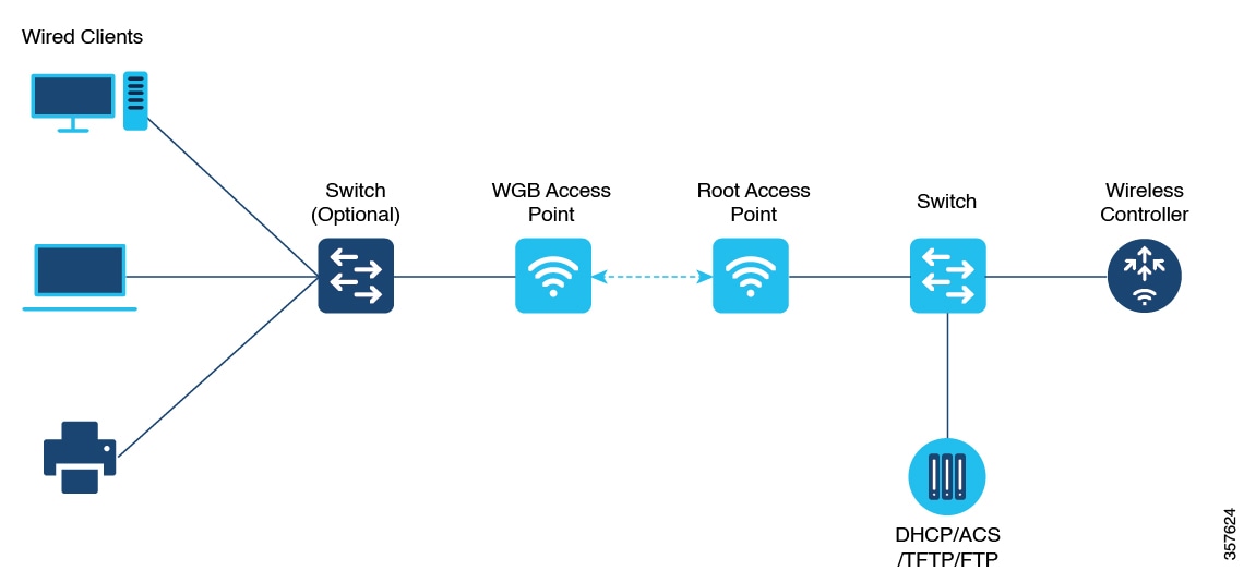
A workgroup bridge (WGB) is an Access Point (AP) mode to provide wireless connectivity to wired clients that are connected to the Ethernet port of the WGB AP. A WGB connects a wired network over a single wireless segment by learning the MAC addresses of its wired clients on the Ethernet interface and reporting them to the WLC through infrastructure AP using Internet Access Point Protocol (IAPP) messaging. The WGB establishes a single wireless connection to the root AP, which in turn, treats the WGB as a wireless client.

Figure 1. Example of a WGB

Starting from Cisco IOS XE Cupertino 17.8.1, WGB is supported on the following Cisco Catalyst 9100 Series Access Points.

  • Cisco Catalyst 9105

  • Cisco Catalyst 9115

  • Cisco Catalyst 9120

Starting from Cisco IOS XE Dublin 17.10.1, WGB is supported on the following Cisco Catalyst 9100 Series Access Points.

  • Cisco Catalyst 9124

  • Cisco Catalyst 9130

From Cisco IOS XE Cupertino 17.9.1 onwards, WGB supports one radio for uplink (backhaul) connectivity and another radio for serving wireless clients. This feature is supported on the Cisco 11AX APs such as Cisco Catalyst 9105 APs, Cisco Catalyst 9115 APs, Cisco Catalyst 9120 APs.

OPEN and PSK security (WPA2 Personal) based wireless clients can be associated to WGB independent of its uplink connectivity, but they will not be able to pass traffic unless WGB has uplink connectivity. Radius server must be configured and the WGB should have uplink connectivity for authentication of wireless clients to 802.1x security (WPA2 Enterprise) WLAN. Both IPv4 and IPv6 traffic forwarding is supported for wireless clients. Static IP and Passive Client support is enabled by default on these WLANs.

The following features are supported for use with a WGB:

Table 1. WGB Feature Matrix

Feature

Cisco Wave 2 APs

Cisco 11AX APs

802.11r

Supported

Supported

QOS

Supported

Supported

UWGB mode

Supported

Not supported

IGMP Snooping or Multicast

Supported

Supported

802.11w

Supported

Supported

PI support (without SNMP)

Not supported

Not supported

IPv6

Supported

Supported

VLAN

Supported

Supported

802.11i (WPAv2)

Supported

Supported

Broadcast tagging/replicate

Supported

Supported

Unified VLAN client

Supported

Supported

WGB client

Supported

Supported

802.1x – PEAP, EAP-FAST, EAP-TLS

Supported

Supported

NTP

Supported

Supported

Wired client support on all LAN ports

Supported in all Wired-0, 1 and LAN ports 1, 2, and 3

Supported in all Wired-0, 1 and LAN ports 1, 2, and 3

Second radio wireless client support

Not supported

Supported

The following table shows the supported and unsupported authentication and switching modes for Cisco APs when connecting to a WGB.


Note


Workgroup Bridge mode is supported on the WiFi6 Pluggable Module from Cisco IOS XE Bengaluru 17.6.1.


Table 2. Supported Access Points and Requirements

Access Points

Requirements

Cisco Aironet 2800, 3800, 4800, 1562, and Cisco Catalyst 9105, 9115, 9120, 9124, and 9130, IW6300 and ESW6300 Series

CAPWAP image starting from Cisco AireOS 8.8 release.

  • MAC filtering is not supported for wired clients.

  • Idle timeout is not supported for both WGB and wired clients.

  • Session timeout is not applicable for wired clients.

  • Web authentication is not supported.

  • The total number of clients supported by WGB (wired + wireless) is limited to 20 clients.

  • If you want to use a chain of certificates, copy all the CA certificates to a file and install it under a trust point on the WGB, else server certificate validation may fail.

  • Wired clients connected to a WGB inherit the WGB's QoS and AAA override attributes.

  • To enable the WGB to communicate with the root AP, create a WLAN and make sure that Aironet IE is enabled under the Advanced settings.

  • WPA2 Enterprise security works only if the uplink WLAN is enabled for FlexConnect local switching or Fabric enabled WLAN.

  • Radius override is not supported for wireless clients that are associated with WGB WLANs.

  • WGB does not support 802.1X wired client authentication when used with power injector.

    The power-injector drops all EAPOL packets received from the wired client and does not forward it to the WGB's wired0 interface. In such cases, use PoE plus hub behind the wired0 interface and connect the wired clients to the hub.

  • After WGB reload, the WGB 802.1X wired clients behind a hub do not trigger authentication automatically, unless done manually.

    After WGB is reloaded the WGB dot1x wired clients which are behind a hub remain authenticated or connected on their side and do not get notified that the WGB is reloaded. Clients are also not shown on the WGB bridge table. The client interfaces must be manually disabled and enabled back to trigger authentication.

  • When the 802.1X wired client Ethernet interface is disabled and then enabled again, client authentication might fail for some of dot1x wired clients, at times.

Configure a WGB on a WLAN

Deploy a WGB so that connected wired devices can access the network via WLAN.
WGBs allow wired devices to join a wireless network by bridging their wired connections over Wi-Fi. This configuration is used in environments where direct wireless capability is not available for all devices.

Before you begin

Ensure WLAN security (such as authentication and encryption) is already configured.

Procedure


Step 1

Enter global configuration mode.

Example:

Device# configure terminal 

Step 2

Enter WLAN configuration submode.

Example:

Device(config)# wlan profile-name

The profile-name is the profile name of the configured WLAN.

Step 3

Configure the Cisco Client Extensions option and sets the support of Aironet IE on the WLAN.

Example:

Device(config-wlan)# ccx aironet-iesupport

Step 4

Exit the WLAN configuration submode.

Example:

Device(config-wlan)# exit

Step 5

Configure WLAN policy profile and enters the wireless policy configuration mode.

Example:

Device(config)# wireless profile policy profile-policy

Step 6

Add a description for the policy profile.

Example:

Device(config-wireless-policy)# description "test-wgb"

Step 7

Assign the profile policy to the VLAN.

Example:

Device(config-wireless-policy)# vlan vlan-no

Step 8

Configure WGB VLAN client support.

Example:

Device(config-wireless-policy)# wgb vlan

Step 9

Configure WGB broadcast tagging on a WLAN.

Example:

Device(config-wireless-policy)# wgb broadcast-tagging

Step 10

Restart the policy profile.

Example:

Device(config-wireless-policy)# no shutdown

Step 11

Exit the wireless policy configuration mode.

Example:

Device(config-wireless-policy)# exit

Step 12

Configure policy tag and enters policy tag configuration mode.

Example:

Device(config)# wireless tag policy policy-tag 

Step 13

Map a policy profile to a WLAN profile.

Example:

Device(config-policy-tag)# wlan profile-name policy profile-policy

Step 14

Exit policy tag configuration mode, and returns to privileged EXEC mode.

Example:

Device(config-policy-tag)# end

The WGB is now configured and can join the designated WLAN, bridging its wired clients to the wireless network.

Verify the status of a WGB on the controller

Use these commands to verify the status of a WGB.

To display the wireless-specific configuration of active clients, use this command:

Device# show wireless client summary

To display the WGBs on your network, use this command:

Device# show wireless wgb summary

To display the details of wired clients that are connected to a particular WGB, use this command:

Device# show wireless wgb mac-address 00:0d:ed:dd:25:82 detail

Configure AP as WGB

Configure Cisco Wave 2 APs or 11AX APs in WGB or CAPWAP AP mode (CLI)

Set up the AP mode and management configuration for Cisco APs using the CLI.
This task is applicable when you need to quickly reconfigure the AP operation mode between Workgroup Bridge and CAPWAP using the AP's command-line interface.

Procedure


Step 1

Enters the privileged mode of the AP.

Example:

Device# enable

Step 2

Move the AP in to the Workgroup Bridge mode.

Example:

Device# ap-type workgroup-bridge

Step 3

Configures DHCP or static IP address using the configure ap address ipv4 dhcp or configure ap address ipv4 static ip-address netmask gateway-ipaddress command.

Example:

DHCP IP Address

Device# configure ap address ipv4 dhcp

Static IP Address

Device# configure ap address ipv4 static 10.10.10.2 255.255.255.234 192.168.4.1

Step 4

Configure an username for the AP management.

Example:

Device# configure ap management add username username password password secret secret

Step 5

Configure the AP hostname.

Example:

Device# configure ap hostname host-name

The AP is successfully configured in the selected mode with the desired network and management settings.

Configure an SSID profile for Cisco Wave 2 and 11AX APs (CLI)

Set up secure Wi-Fi profiles for Wave 2 and 11AX APs, allowing client authentication and traffic management using the AP CLI.
This configuration is performed on the AP console and does not apply to the controller CLI. Choose authentication and QoS settings best suited for your environment.

Before you begin

Ensure you have access to the AP console and any preshared keys or EAP profiles needed for authentication.

Procedure


Step 1

Create an SSID profile and specify authentication (open, PSK, or EAP) and key management options.

Example:

SSID profile with open authentication:

Device# configure ssid-profile test WRT s1 authentication open

SSID profile with PSK authentication:

Device# configure ssid-profile test WRT s1 authentication psk 1234 key-management dot11r 

SSID profile with EAP authentication:

Device# configure ssid-profile test WRT s1 authentication eap profile test2 key-management dot11r 

Choose the authentication protocol that matches your deployment requirements.

Step 2

Attach the SSID profile to a radio interface.

Example:

Device# configure dot11radio radio-interface mode wgb ssid-profile profle-name

Binds the SSID profile for wireless bridge operations.

Step 3

(Optional) Configure the DTIM period for the SSID profile.

Example:

Device# configure ssid-profile profile-name ssid ssid-name dtim-period ssid-name

Sets the delivery traffic indication message interval for broadcast/multicast traffic.

Note


Supported for wireless clients from Cisco IOS XE Cupertino 17.9.1 onwards.

Step 4

(Optional) Create a QoS profile.

Example:

Device# configure qos profile qos-profile gold

Gold, silver, platinum, and bronze options are available to prioritize traffic.

Step 5

(Optional) Map the QoS profile to the SSID profile.

Example:

Device# configure ssid-profile profile-name ssid ssid-name qos profile qos-profile-name

Enables traffic prioritization for the specified SSID profile.

Note


Supported for wireless clients from Cisco IOS XE Cupertino 17.9.1 onwards.

Step 6

(Optional) Delete and SSID.

Example:

Device# configure ssid-profile profle-name delete

Step 7

(Optional) Display summary of configured and connected SSIDs.

Example:

Device# show wgb ssid

Step 8

(Optional) Display management, control, and data packet statistics for WGB SSIDs.

Example:

Device# show wgb packet statistics

The SSID profile is configured for the AP and mapped to the desired radio interface. Wireless clients can now connect using the specified authentication mode, traffic is prioritized according to QoS settings, and you can monitor SSID and packet statistics as needed.

Configure the authentication server (CLI)

Set up a primary or secondary RADIUS authentication server for network access control using CLI.
RADIUS servers provide centralized authentication, authorization, and accounting (AAA) management for users connecting to the network.

Before you begin

Ensure you have the IP address, port number, and shared secret for the RADIUS server you are configuring.

Procedure


Configure a RADIUS authentication server with a primary or secondary role, IP version, port, and shared secret.

Example:


Device# configure radius authentication primary|secondary add ipv4|ipv6 address radius-server-ip-address port radius-server-port-number secret radius-secret
          

Device# configure radius authentication primary add ipv4 address 192.168.1.2 port 1812 secret Cisco123
          

Configures a primary (or secondary) RADIUS server with the specified IP version (IPv4 or IPv6), server address, UDP port, and authentication secret.

  1. primary|secondary: keyword specifies if the RADIUS server is primary or secondary.

  2. ipv4|ipv6: identifies the IP address type.

  3. radius-server-ip-address: is the management IP address of the RADIUS server.

  4. radius-server-port-number: is typically 1812 for authentication.

  5. radius-secret: is a shared secret between the device and the RADIUS server (case-sensitive).


The RADIUS authentication server is now configured. The device can authenticate users against the designated server.

Configure Dot1X credential (CLI)

Configure or remove a Dot1X credential profile, and manage WGB client authentication using CLI commands.
Dot1X credentials are used to authenticate devices securely to the network. You can create or remove these credentials as required, and clear authenticated Workgroup Bridge (WGB) clients using dedicated commands.

Before you begin

Ensure the device is in global configuration mode before issuing these commands.

Procedure


Step 1

Configure a Dot1X credential profile with username and password.

Example:


Device(config)# configure dot1x credential profile-name username username password password
          

Creates or updates a Dot1X credential profile with the specified username and password.

Step 2

Delete a Dot1X credential profile.

Example:


Device(config)# configure dot1x credential profile-name delete
          

Removes the specified Dot1X credential profile.

Step 3

Clear a WGB client session based on MAC address or clear all WGB clients.

Example:


Device# clear wgb client single mac-address
          
Deauthenticates a specific WGB client identified by MAC address. To clear all WGB clients, use:
Device# clear wgb client all

Dot1X credentials and WGB client sessions are managed according to your chosen operations.

Configure an EAP profile (CLI)

Use this procedure to create, manage, or delete EAP profiles on your device for authentication using the CLI.
An EAP profile defines the authentication method for wireless users. You can configure various methods and associate trustpoints or credentials to strengthen security for wireless authentication.

Before you begin

Enable global configuration mode on the device and verify access to CLI.

Procedure


Step 1

Configure an EAP profile and set the EAP method.

Example:

Device# configure eap-profile profile-name method method-name

Configures an EAP profile with the chosen method.

The method-name can be:

  • fast

  • leap

  • peap

  • tls

Step 2

Associate a trustpoint with the EAP profile . Use either the default or a specific name.

Example:

EAP profile to Trustpoint with MIC Certificate:

Device# configure eap-profile profile-name trustpoint default

EAP profile to Trustpoint with CA Certificate:

Device# configure eap-profile profile-name trustpoint name trustpoint-name

Configures an EAP profile with a trustpoint for authentication.

Step 3

Attach a CA trustpoint to the EAP profile.

Example:

Device# configure eap-profile profile-name trustpoint {default | name trustpoint-name}

Attaches the CA trustpoint.

Note


With the default profile, WGB uses the internal MIC certificate for authentication.

Step 4

Configure the 802.1X credential profile for the EAP profile.

Example:

Device# configure eap-profile profile-name dot1x-credential profile-name

Configures the 802.1X credential profile associated with the EAP profile.

Step 5

(Optional) Delete an EAP profile .Delete an EAP profile.

Example:

Device# configure eap-profile profile-name delete

Step 6

(Optional) Display the WGB EAP dot1x credential profile summary .Display the WGB EAP dot1x credential profile summary.

Example:

Device# show wgb eap dot1x credential profile

Step 7

(Optional) Display the EAP profile summary.

Example:

Device# show wgb eap profile

Step 8

(Optional) Display all configured EAP and dot1x profiles .Display all configured EAP and dot1x profiles.

Example:

Device# show wgb eap profile all

The EAP profile is now configured as required. You can display or modify EAP profiles as needed to support different authentication strategies.

Configure manual-enrollment of a trustpoint for WGB (CLI)

Manually configure and enroll a trustpoint on a WGB to enable certificate-based security authentication via CLI.
A trustpoint defines a Certification Authority (CA) used to issue certificates for device authentication. Manual enrollment is used when automatic enrollment via HTTP/SCEP is not available.

Before you begin

Ensure that the WGB configuration is complete and the required CA certificate is accessible. You must have administrator access to the CLI and all necessary server and certificate information.

Procedure


Step 1

Configure a trustpoint on the WGB and set the enrollment method to terminal.

Example:

Device# configure crypto pki trustpoint ca-server-name enrollment terminal

Defines a new trustpoint and specifies that certificate content will be entered manually.

Step 2

Authenticate the trustpoint and input the base 64 encoded CA certificate.

Example:

Device# configure crypto pki trustpoint ca-server-name authenticate

Authenticates a trustpoint by pasting the CA-signed certificate. End certificate input by typing quit on a new line.

Step 3

Configure the private key size for the trustpoint.

Example:

Device# configure crypto pki trustpoint ca-server-name key-size key-length

Sets the RSA key pair length for the trustpoint’s private key.

Step 4

Configure the subject name attributes for the trustpoint’s certificate.

Example:

Device# configure crypto pki trustpoint ca-server-name subject-name name 2ltr-country-code state-name locality org-name org-unit email

Example:

Device# configure crypto pki trustpoint 
ca-server-US subject-name test US CA abc cisco AP test@cisco.com

Specifies certificate subject fields, matching your organization’s naming policy.

Step 5

Generate a Certificate Signing Request (CSR) on the WGB and enroll the trustpoint.

Example:

Device# configure crypto pki trustpoint ca-server-name enroll

Generates the private key and a CSR; provide the CSR output to your CA server for certificate signing.

Step 6

Import the signed certificate from the CA back into the WGB trustpoint.

Example:

Device# configure crypto pki trustpoint ca-server-name import certificate

Installs the issued device certificate. End certificate input with the quit command on a new line.

Step 7

(Optional) Delete the trustpoint if reconfiguration is needed.

Example:

Device# configure crypto pki trustpoint ca-server-name delete

Removes a trustpoint configuration from the device.

Step 8

(Optional) Display the trustpoint summary.

Example:

Device# show crypto pki trustpoint

Shows all trustpoints configured on the device.

Step 9

(Optional) Display certificates associated with a trustpoint.

Example:

Device# show crypto pki trustpoint ca-server-name certificate

Inspect the contents of certificates for a specific trustpoint.


Manual trustpoint enrollment is now complete on the WGB. The device can use the certificates for secure authentication and establish connections as required for network operation.

Configure auto-enrollment of a trustpoint for workgroup bridge (CLI)

Enable automatic certificate enrollment for secure communication by configuring a trustpoint and CA enrollment in a WGB deployment.
Auto-enrollment of a trustpoint streamlines certificate management for workgroup bridges by allowing automatic acquisition and renewal of CA certificates.

Before you begin

Ensure the device is running the appropriate WGB image and has connectivity to the CA server.

Procedure


Step 1

Configure the trustpoint and specify the CA server enrollment URL.

Example:

Device# configure crypto pki trustpoint ca-server-name enrollment url ca-server-url

Enrolls a trustpoint in WGB using the CA server URL.

Step 2

Authenticate the trustpoint by fetching the CA certificate from the CA server.

Example:

Device# configure crypto pki trustpoint ca-server-name authenticate

Fetches the CA certificate for trustpoint authentication.

Step 3

Set the private key size for the trustpoint.

Example:

Device# configure crypto pki trustpoint ca-server-name key-size key-length

Example:

Device# configure crypto pki trustpoint 
ca-server-Us key-size 60

Step 4

Configure the subject name for the trustpoint.

Example:

Device# configure crypto pki trustpoint ca-server-name subject-name name 2ltr-country-code state-name locality org-name org-unit email

Example:

Device# configure crypto pki trustpoint 
ca-server-US subject-name test US CA abc cisco AP test@cisco.com

Customize the subject name parameters as needed for your deployment.

Step 5

Enroll the trustpoint to request a signed certificate from the CA server.

Example:

Device# configure crypto pki trustpoint ca-server-name enroll

Initiates the certificate enrollment request to the CA server.

Step 6

Enable auto-enrollment and specify the renewal percentage threshold.

Example:

Device# configure crypto pki trustpoint ca-server-name auto-enroll enable renew-percentage

Example:

Device# configure crypto pki trustpoint 
ca-server-US auto-enroll enable  10

Use disable to turn off auto-enroll if needed.

Step 7

(Optional) Delete the trustpoint if it is no longer required.

Example:

Device# configure crypto pki trustpoint ca-server-name delete

Removes the trustpoint from the configuration.

Step 8

(Optional) Display the summary of trustpoints.

Example:

Device# show crypto pki trustpoint

Lists all configured trustpoints and their status.

Step 9

(Optional) Display the certificate for a specific trustpoint.

Example:

Device# show crypto pki trustpoint ca-server-name certificate

Shows the certificate configured for the specified trustpoint.

Step 10

(Optional) Display the PKI timer information.

Example:

Device# show crypto pki timers

Displays timer settings related to PKI operations.


The trustpoint is now auto-enrolled and managed on the WGB, ensuring secure and automated certificate renewal.

Configure manual certificate enrollment using TFTP server (CLI)

Manual certificate enrolment allows devices to obtain certificates from a TFTP server, which is essential for secure communications.

Procedure


Step 1

Specify the enrollment method to retrieve the CA certificate and client certificate for a trustpoint in WGB.

Example:

Device# configure crypto pki trustpoint 
ca-server-name enrollment addr/file-name

Specifies the enrolment method to retrieve the CA certificate and client certificate for a trustpoint in WGB.

Step 2

Authenticate the CA certificate from the specified TFTP server.

Example:

Device# configure crypto pki trustpoint 
ca-server-name authenticate

Retrieves the CA certificate and authenticates it from the specified TFTP server. If the file specification is included, the WGB will append the extension “.ca” to the specified filename.

Step 3

Configure the private key size for the trustpoint.

Example:

Device# configure crypto pki trustpoint 
ca-server-name key-size key-length

Configures a private key size.

Step 4

Set the subject name for the trustpoint.

Example:

Device# configure crypto pki trustpoint 
ca-server-name subject-name test US CA abc cisco AP test@cisco.com

Configures the subject name.

Step 5

Generate a private key and certificate signing request (CSR).

Example:

Device# configure crypto pki trustpoint 
ca-server-name enroll

Generate a private key and Certificate Signing Request (CSR) and writes the request out to the TFTP server. The filename to be written is appended with the extension “.req”.

Step 6

Import the signed certificate into WGB using TFTP at the console terminal, which retrieves the granted certificate.

Example:

Device# configure crypto pki trustpoint 
ca-server-name import certificate

Import the signed certificate in WGB using TFTP at the console terminal, which retrieves the granted certificate. The WGB will attempt to retrieve the granted certificate using TFTP using the same filename and the file name appended with “.crt” extension.

Step 7

(Optional) Display the trustpoint summary.

Example:

Device# show crypto pki trustpoint

Displays the trustpoint summary.

Step 8

(Optional) Display the content of the certificates for a trustpoint.

Example:

Device# show crypto pki trustpoint trustpoint-name certificate

Displays the content of the certificates that are created for a trustpoint.


Import the PKCS12 format certificates from the TFTP server (CLI)

Importing PKCS12 format certificates is essential for establishing secure communications in network devices.

Procedure


Step 1

Import the PKCS12 format certificate from the TFTP server.

Example:

Device# configure crypto pki trustpoint 
                        ca-server-name import pkcs12 tftp addr/file-name password pwd

Example:

Device# configure crypto pki trustpoint 
                        ca-server-US import pkcs12 tftp://10.8.0.6/all_cert.p12 password ******

Step 2

(Optional) Display the trustpoint summary.

Example:

Device# show crypto pki trustpoint

Step 3

(Optional) Display the content of the certificates created for a trustpoint.

Example:

Device# show crypto pki trustpoint trustpoint-name certificate

Example:

Device# show crypto pki trustpoint ca-server-US certificate

Configure radio interface for workgroup bridges (CLI)

From the available two radio interfaces, before configuring WGB or UWGB mode on one radio interface, configure the other radio interface to root AP mode.

Procedure


Step 1

Configure a radio interface as root AP.

Example:

Device# configure dot11Radio radio-int mode root-ap

Example:

Device# configure dot11Radio 0/3/0 mode root-ap

Maps a radio interface as root AP.

Note


When an active SSID or EAP profile is modified, you need to reassociate the profile to the radio interface for the updated profile to be active.

Step 2

Configure the WLAN at the root AP mode radio.

Example:

Device# configure dot11radio value wlan add ssid-profile-name ssid-number

Example:

Device# configure dot11radio dotradiovalue wlan add ssid-profile-name ssid-number

Enter the SSID profile name and SSID number between 1 and 16. Value can be 0 or 1.

Step 3

Delete WLAN from the radio configuration.

Example:

Device# configure dot11radio dotradiovalue wlan delete ssid-profile-name

Enter the SSID profile name. Value can be 0 or 1.

Step 4

Configure a radio channel to broadcast the SSID.

Example:

Device# configure dot11radio value channel channel-number width

Example:

Device# configure dot11radio value channel channel-number width

The channel numbers are between 1 and 173. The channel width values are 20, 40, 80, and 160.

Note

 
  • Only 20MHz channel width is supported on radio 0 (2.4-GHz band).

  • If radar is detected on a configured channel on radio 1, then the channel automatically changes to a non-DFS channel with a channel width of 20MHz. The administrator must reset the radio to bring it back to the configured channel.

Step 5

Configure the periodic beacon interval in milliseconds.

Example:

Device# configure dot11radio dotradiovalue beacon-period beacon-interval

The value range is between 2 and 2000 milliseconds.

Step 6

Maps a radio interface to a WGB SSID profile.

Example:

Device# configure dot11Radio 0/3/0 mode wgb ssid-profile ssid-profile-name

Maps a radio interface to a WGB SSID profile.

Step 7

Maps a radio interface to a UWGB SSID profile.

Example:

Device# configure dot11Radio radio-int mode uwgb mac-addr ssid-profile ssid-profile-name

Maps a radio interface to a WGB SSID profile.

Step 8

Configures a radio interface.

Example:

Device# configure dot11Radio radio-int mode enable

After configuring the uplink to the SSID profile, we recommend that you disable and enable the radio for the changes to be active.

Step 9

Configures a radio antenna.

Example:

Device# configure dot11Radio radio-int antenna a-antenna

Configures a radio antenna.

Step 10

Configures the radio interface encryption mode.

Example:

Device# configure dot11Radio radio-int encryption mode ciphers aes-ccm

Configures the radio interface.

Step 11

Configures the device channel rate.

Example:

Device# configure wgb mobile rate basic 6 9 18 24 36 48 54

Configures the device channel rate.

Step 12

Configure the threshold duration and signal strength to trigger scanning.

Example:

Device# configure wgb mobile period seconds thres-signal

Configure the threshold duration and signal strength to trigger scanning.

Step 13

Configures the static roaming channel.

Example:

Device# configure wgb mobile station interface dot11Radio 0/3/0 scan channel-number add

Configures the static roaming channel.

Step 14

(Optional) Delete the mobile channel.

Example:


                        Device# configure wgb mobile station interface dot11Radio 0/3/0 scan channel-number delete
                    

Step 15

(Optional) Disable the mobile channel.

Example:

Device# configure wgb mobile station interface dot11Radio 0/3/0 scan disable

Step 16

(Optional) Configure the beacon miss-count.

Example:

Device# configure wgb beacon miss-count value

Note


When you set the beacon miss-count value to 10 or lower, then the beacon miss-count gets disabled. Set the value to 11 or higher to enable this function.

Step 17

(Optional) Display the Wi-Fi station statistics.

Example:

Device# show wgb wifi wifi-interface stats

Step 18

(Optional) Display the radio antenna statistics.

Example:

Device# show controllers dot11Radio radio-interface antenna

Step 19

(Optional) Display the mobile station channels scan configuration.

Example:

Device# show wgb mobile scan channel

Step 20

(Optional) Display the configuration that is stored in the NV memory.

Example:

Device# show configuration

Step 21

(Optional) Display the running configuration in the device.

Example:

Device# show running-config

Configure workgroup bridge timeouts (CLI)

Use this task to configure various timeout values that control workgroup bridge (WGB) behavior, improving reliability and performance.

  • Set specific timeout limits for association, authentication, EAP, DHCP response, and channel scan processes.

Timeout values affect how long the WGB waits for events before triggering corrective actions or failure notices.

This task applies to Cisco devices in environments where precise timeout management is needed for workgroup bridge operations and troubleshooting.

Before you begin

Ensure you have privileged EXEC access on the device.

  • Verify device compatibility and active WGB configuration.

Procedure


Step 1

Configure the WGB association response timeout.

Example:

Device# configure wgb association response timeout response-millisecs

Default: 5000 ms; Range: 300–5000 ms.

Step 2

Configure the WGB authentication response timeout.

Example:

Device# configure wgb authentication response timeout response-millisecs

Default: 5000 ms; Range: 300–5000 ms.

Step 3

Configure the Universal WGB client response timeout.

Example:

Device# configure wgb uclient timeout timeout-secs

Default: 60 s; Range: 1–65535 s.

Step 4

Configure the WGB EAP timeout.

Example:

Device# configure wgb eap timeout timeout-secs

Default: 3 s; Range: 2–60 s.

Step 5

Configure the WGB channel scan timeout.

Example:

Device# configure wgb channel scan timeout {fast | slow | medium}

Select scan speed according to site requirements.

Step 6

Configure the WGB DHCP response timeout.

Example:

Device# configure wgb dhcp response timeout timeout-secs

Default: 60 s; Range: 1000–60000 ms.

Step 7

Display the WGB association summary.

Example:

Device# show wgb dot11 association

Display associated WGB clients and related statistics.


The configured timeout parameters apply immediately and affect how the WGB responds to events and failures.

For example, to set the WGB association response timeout to 4000 ms:

Device# configure wgb association response timeout 4000

What to do next

Verify timeout settings by using display commands and monitoring WGB behavior.

  • Adjust timeouts as needed for specific network or client stability.

Configure bridge forwarding for workgroup bridge (CLI)

Before you begin

The Cisco Wave 2 and 11AX APs as Workgroup Bridge recognizes the Ethernet clients only when the traffic has the bridging tag.

We recommend setting the WGB bridge client timeout value to default value of 300 seconds, or less in environment where change is expected, such as:

  • Ethernet cable is unplugged and plugged back.

  • Endpoint is changed.

  • Endpoint IP is changed (static to DHCP and vice versa).

If you need to retain the client entry in the WGB table for a longer duration, we recommend you increase the client WGB bridge timeout duration.

Procedure


Step 1

Add a WGB client using the MAC address.

Example:

Device# configure wgb bridge client add mac-address

Example:

Device# configure wgb bridge client add F866.F267.7DFB

Step 2

Configure the WGB bridge client timeout. Default timeout value is 300 seconds. The valid range is between 10 and 1000000 seconds.

Example:

Device# configure wgb bridge client timeout timeout-secs

Example:

Device# configure wgb bridge client timeout 400

Step 3

Display the WGB wired clients over the bridge.

Example:

Device# show wgb bridge

Step 4

Display the WGB Gigabit wired clients over the bridge.

Example:

Device# show wgb bridge wired gigabitEthernet interface

Example:

Device# show wgb bridge wired gigabitEthernet 0/1

Step 5

Display the WGB bridge radio interface summary.

Example:

Device# show wgb bridge dot11Radio interface-number

Example:

Device# show wgb bridge dot11Radio 0/3/1

Information About Simplifying WGB Configuration

From Cisco IOS XE Cupertino 17.8.1, it is possible to configure WGB in multiple Cisco access points (APs) simultaneously. By importing a running configuration, you can deploy multiple WGBs in a network and make them operational quicker. When new Cisco APs are added to the network, you can transfer an existing or working configuration to the new Cisco APs to make them operational. This enhancement eliminates the need to configure multiple Cisco APs using CLIs, after logging into them.

A network administrator can onboard Cisco APs using either of the following methods:

  • Upload the working configuration from an existing Cisco AP to a server and download it to the newly deployed Cisco APs.

  • Send a sample configuration to all the Cisco APs in the deployment.

This feature is supported only on the following Cisco APs:

  • Cisco Aironet 1562 Access Points

  • Cisco Aironet 2800 Access Points

  • Cisco Aironet 3800 Access Points

  • Cisco Catalyst 9105 Access Points

  • Cisco Catalyst 9115 Access Points

  • Cisco Catalyst 9120 Access Points

  • Cisco Catalyst IW6300 Series Heavy Duty Access Points

For latest support information on various features in Cisco Wave 2 and 802.11ax (Wi-Fi 6) Access Points in Cisco IOS XE releases, see the Feature Matrix for Wave 2 and 802.11ax (Wi-Fi 6) Access Points document.

Configuring Multiple WGBs (CLI)

Perform the following procedure on the APs in WGB mode.

Procedure

  Command or Action Purpose

Step 1

enable

Example:

Device# enable

Enters privileged EXEC mode.

Step 2

copy configuration upload{sftp:| tftp:} ip-address [directory] [file-name]

Example:

Device# copy configuration upload sftp: 10.10.10.1 C:sample.txt

Creates upload configuration file and uploads to the SFTP or TFTP server using the specified path.

Step 3

copy configuration download{sftp:| tftp:} ip-address [directory] [file-name]

Example:

Device# copy configuration download sftp: 10.10.10.1 C:sample.txt

Downloads the configuration file and replaces the old configuration in the AP and reboots the WGB. When the device restarts, new configuration is applied.

Step 4

show wgb dot11 association

Example:

Device# show wgb dot11 association

Lists the WGB uplink information.

Step 5

show version

Example:

Device# show version

Displays the AP software information.

Verifying WGB Configuration

After completing the configuration download and reboot of the AP, the WGB rejoins the network. Use the show logging command to list and verify the download events that are captured in the debug logs:

Device# show logging

Jan 13 18:19:17 kernel: [*01/13/2022 18:19:17.4880] WGB - Applying download config...
Jan 13 18:19:18 download_config: configure clock timezone UTC
Jan 13 18:19:18 download_config: configure dot1x credential dot1x_profile username wifiuser password U2FsdGVkX1+8PWmAOnFO8BXyk5EAphMy2PmhPPhWV0w=
Jan 13 18:19:18 download_config: configure eap-profile eap_profile method PEAP
Jan 13 18:19:18 download_config: configure eap-profile eap_profile dot1x-credential dot1x_profile
Jan 13 18:19:18 chpasswd: password for user changed
Jan 13 18:19:18 kernel: [*01/13/2022 18:19:18.7260] chpasswd: password for user changed
Jan 13 18:19:18 kernel: [*01/13/2022 18:19:18.7610] 
Jan 13 18:19:18 kernel: [*01/13/2022 18:19:18.7610]  Management user configuration saved successfully
Jan 13 18:19:18 kernel: [*01/13/2022 18:19:18.7610] 
Jan 13 18:19:18 kernel: [*01/13/2022 18:19:18.7650] Warning!!! Attach SSID profile with the radio to use the new changes.
Jan 13 18:19:18 kernel: [*01/13/2022 18:19:18.7650] 
Jan 13 18:19:18 kernel: [*01/13/2022 18:19:18.7650]  Dot1x credential configuration has been saved successfully
Jan 13 18:19:18 kernel: [*01/13/2022 18:19:18.7650] 
Jan 13 18:19:18 kernel: [*01/13/2022 18:19:18.7740] Warning!!! Attach SSID profile with the radio to use the new changes.
Jan 13 18:19:18 kernel: [*01/13/2022 18:19:18.7740] 
Jan 13 18:19:18 kernel: [*01/13/2022 18:19:18.7740]  EAP profile configuration has been saved successfully
Jan 13 18:19:18 kernel: [*01/13/2022 18:19:18.7740] 
Jan 13 18:19:18 kernel: [*01/13/2022 18:19:18.7790] Warning!!! Attach SSID profile with the radio to use the new changes.
Jan 13 18:19:18 kernel: [*01/13/2022 18:19:18.7790] 
Jan 13 18:19:18 kernel: [*01/13/2022 18:19:18.7790]  EAP profile configuration has been saved successfully
Jan 13 18:19:18 kernel: [*01/13/2022 18:19:18.7790] 
Jan 13 18:19:18 kernel: [*01/13/2022 18:19:18.7830] Warning!!! Attach SSID profile with the radio to use the new changes.
Jan 13 18:19:18 kernel: [*01/13/2022 18:19:18.7830] 
Jan 13 18:19:18 download_config: configure ssid-profile psk ssid alpha_psk authentication psk U2FsdGVkX18meBfFFeiC4sgkEmbGPNH/ul1dne6h/m8= key-management wpa2
Jan 13 18:19:18 kernel: [*01/13/2022 18:19:18.7930] Warning!!! Attach SSID profile with the radio to use the new changes.
Jan 13 18:19:18 kernel: [*01/13/2022 18:19:18.7930] 
Jan 13 18:19:18 kernel: [*01/13/2022 18:19:18.7930]  EAP profile configuration has been saved successfully
Jan 13 18:19:18 kernel: [*01/13/2022 18:19:18.7930] 
Jan 13 18:19:18 download_config: configure ssid-profile open ssid alpha_open authentication open
Jan 13 18:19:18 download_config: configure ssid-profile openax ssid alpha_open_ax authentication open
Jan 13 18:19:18 kernel: [*01/13/2022 18:19:18.8650]  SSID-Profile dot1xpeap has been saved successfully 
Jan 13 18:19:18 kernel: [*01/13/2022 18:19:18.8650] 
Jan 13 18:19:18 kernel: [*01/13/2022 18:19:18.9270]  SSID-Profile psk has been saved successfully 
Jan 13 18:19:18 kernel: [*01/13/2022 18:19:18.9270] 
Jan 13 18:19:19 kernel: [*01/13/2022 18:19:19.0380]  SSID-Profile open has been saved successfully 
Jan 13 18:19:19 kernel: [*01/13/2022 18:19:19.0380] 
Jan 13 18:19:19 kernel: [*01/13/2022 18:19:19.0380]  SSID-Profile openax has been saved successfully 
Jan 13 18:19:19 kernel: [*01/13/2022 18:19:19.0380] 
Jan 13 18:19:22 download_config: configure wgb broadcast tagging disable
Jan 13 18:19:22 download_config: configure wgb packet retries 64 drop
Jan 13 18:19:22 kernel: [*01/13/2022 18:19:22.9710] Broadcast tagging 0 successfully
Jan 13 18:19:22 kernel: [*01/13/2022 18:19:22.9710] 
Jan 13 18:19:23 download_config: configure dot11Radio 1 mode wgb ssid-profile open
Jan 13 18:19:23 download_config: configure dot11Radio 1 enable
Jan 13 18:19:23 download_config: configure ap address ipv6 disable