Chapter 4. Provisioning Dial Plans with VSPT
Available Languages
Table Of Contents
Provisioning Dial Plans with VSPT
Defining Users and Permissions
Importing an Existing Dial Plan File
Adding Digit Modification Strings
Adding an IN_TRIGGER Result Type for LNP
Provisioning Triggers Components
Adding a Nature of Address Table
Adding a Numbering Plan Indicator Table
Provisioning Dial Plans with VSPT
This chapter provides information and procedures for provisioning dial plans for Cisco Media Gateway Controller Software Release 7.4 using the Voice Services Provisioning Tool (VSPT).
This chapter contains the following sections:
•
Performing an Integrity Check
VSPT provides a graphical user interface (GUI) that allows you to create dial plans and then deploy those dial plans to the Cisco MGC.
You can use the VSPT to perform a variety of provisioning tasks, including:
•
•
•
•
•
The VSPT can be used alone or with Man-Machine Language (MML) commands to provision dial plans for your system. For more information on using MML commands, refer to "Provisioning Dial Plans with MML."
You should have the information described in "Preparing for Dial Plan Provisioning," before beginning your dial plan provisioning session.
When provisioning dial plans, you must first ensure that all system components have been provisioned as described in the Cisco Media Gateway Controller Software Release 7 Provisioning Guide.
VSPT Overview
The VSPT provides a GUI that allows you to create dial plan provisioning sessions.
This section contains the following subsections:
•
The VSPT provides the following capabilities:
•
•
•
•
•
After you finish the provisioning session and click File, Save, and As Working, the VSPT saves your dial plan as the "active" dial plan. After creating the active dial plan, you cannot modify it. To make changes, save the dial plan with another name and commit or deploy the new provisioning session to make the revised dial plan active.
The number of dial plans you can store might be limited by available disk space. Consider deleting old or unwanted dial plans, or saving them to another machine if you do not have sufficient disk space.

Note
Note
Entering MML Names
The names you enter are used to generate MML commands. You must enter a name and a description for each dial plan you provision. In order for you to produce valid MML commands, your MML names must have the following characteristics:
•
•
•
•
•
Entering MML Descriptions
MML descriptions can have as many as 128 characters and can include spaces and symbols. You should use descriptions that help identify the components that you are provisioning. For more information about MML names and descriptions, see "Provisioning Dial Plans with MML."
Starting the VSPT
To start the VSPT, complete the following steps:
Step 1
Step 2
cd /opt/CSCOvsp15
The default directory is /opt/CSCOvsp15. If you installed the VSPT in a different location, navigate to the appropriate directory, then enter:
./dart
The system opens the X-windows interface and the login window is displayed.
Step 3
The preset User Name is admin and the Password is also admin. See the Cisco Media Gateway Controller Software Release 7 Installation and Configuration Guide for more information on setting up user access.
A Welcome window is displayed briefly during the login process, after which the main provisioning window is displayed. (It should be similar to the window shown in Figure 4-1.)
Figure 4-1 Main Provisioning Window
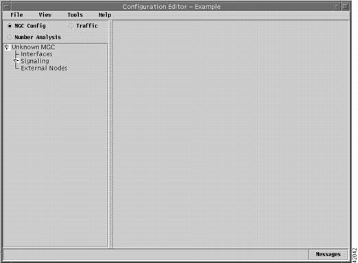
The VSPT main window has two panes. The left pane displays a list of components that you can select. To expand the component list, click the plus sign (+) next to the component name in the left pane. To select a component, click the component name. The right pane displays fields in which you can enter data for the selected component.
Navigating the VSPT
The following sections describe the methods of navigating the VSPT.
Buttons
The VSPT provides buttons and trees to navigate through the system. Click the buttons to add or change network components displayed in the trees. The top of the VSPT main window contains three buttons:
•
•
•
Menu Bar
The VSPT menu bar contains four selections: File, View, Tools, and Help.
File Menu
The File menu provides the following options:
•
•
•
•
•
–
–
–
•
View Menu
The View menu provides the following options:
•
•
•
•
Tools Menu
The Tools menu provides the following options:
•
•
•
•
•
Help Menu
The Help menu displays the "About VSPT" window with information about the current build
Defining Users and Permissions
After you install the VSPT, you can define users and specify their respective permissions.
To define users and specify permissions, complete the following steps:
Step 1
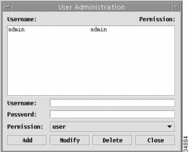
The VSPT User Administration window is displayed (Figure 4-2).
Figure 4-2 VSPT User Administration Window
Step 2
•
•
•
Exiting the VSPT
You can exit the VSPT at any time by performing one of these actions:
•
•
Adding a Dial Plan
You create the dial plan that the MGC node uses to direct the dialed digits to select a specific trunk group. To do so, you need information that you have added to the dial plan worksheet.
Note
The following subsections describe the process of creating the dial plan. The resulting dial plan batch file is provided in the "Viewing Generated MML" section. After you have added your components and trunks, you can commit the session using either the PROV-CPY or the PROV-DPLY command.
Importing an Existing Dial Plan File
During initial provisioning, you can create a dial plan file as a text file using a text editor. Now you can import the text file into the VSPT.

Caution
To import a dial plan, complete the following steps:
Step 1
A dialog box, similar to the one shown in Figure 4-3, is displayed.
Figure 4-3 Importing Dial Plan Files
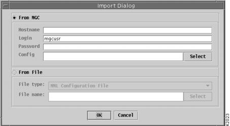
Step 2
Step 3
Step 4
a.
A browser window, similar to the one shown in Figure 4-4, is displayed.
Figure 4-4 Selecting the Dial Plan File to Import
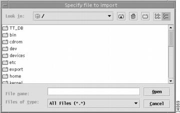
b.
You return to the window shown in Figure 4-3 The full pathname of the dial plan file you selected now appears in the File name box.
Step 5
The dial plan file you indicated is imported.
Adding a Dial Plan File
A dial plan file defines a dial plan for a customer group. If you decide not to import a dial plan file created with a text editor, you can create the dial plan file using the VSPT.
You must first add the dial plan file, and then add the details to the dial plan.
To add a dial plan file, complete the following steps:
Step 1
Step 2
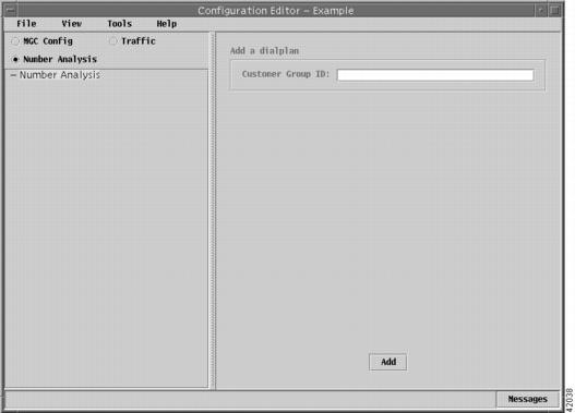
A window, similar to the one shown in Figure 4-5, is displayed.
Step 3
The Customer Group ID is a unique, four-character alphanumeric identifier (starting with a letter) that identifies your dial plan.
Caution
We suggest that you create a sufficiently large number of Customer Group IDs during the initial provisioning of your system to accommodate your anticipated needs, then assign Customer Group IDs to your users as they are needed.
Provisioning new Customer Group IDs for an operational system means that you have to take the SS7 sigPath OOS, which will result in a loss of service for any calls associated with that SS7 sigPath.
Step 4
The Customer Group ID you added appears under Number Analysis.
Figure 4-5 Adding a Dial Plan File
Provisioning the Dial Plan
You provision a dial plan by adding detailed information in two dial plan components:
•
•
The following sections describe the information you need to add to the Results component:
•
•
The sections that describe the information you need to add to the Triggers component starts on Provisioning Triggers Components.
Accessing the Dial Plan File
To access the window for adding dial plan details, complete the following steps:
Step 1
Step 2
Step 3
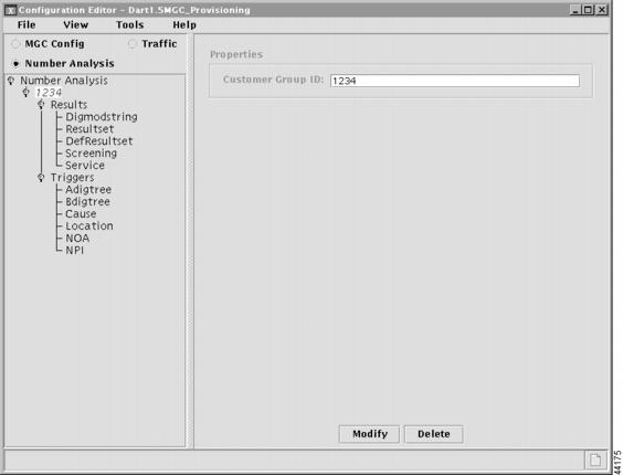
A window, similar to the one shown in Figure 4-6, is displayed.
Figure 4-6 Adding Dial Plan Details
Adding Digit Modification Strings
The digit modification string is used to insert numbers into either the calling or called party number.
To add a digit modification string, complete the following steps:
Step 1
The following dial plan components are displayed:
•
•
•
•
•
Step 2
A window, similar to the one shown in Figure 4-1, is displayed.
Step 3
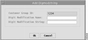
A dialog box, similar to the one shown in Figure 4-8, is displayed.
Step 4
Step 5
The digit modification name and the digit modification string are added to the corresponding columns of the right-hand pane of the window shown in Figure 4-7.
Step 6
Figure 4-7 Adding a Digit Modification String
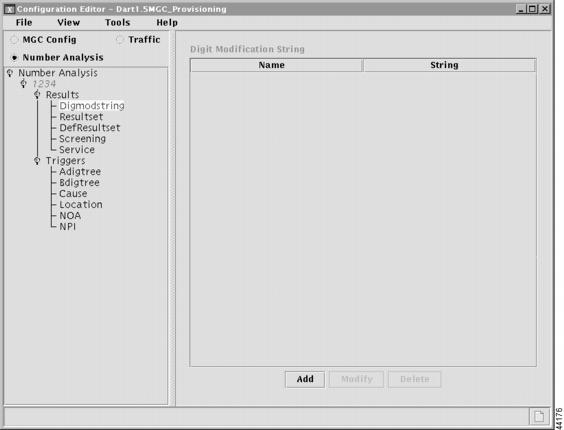
Figure 4-8 Defining a Digit Modification String
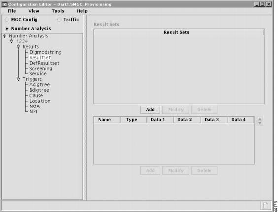
Adding a Result Set
A result set (or table) defines the action to be taken after analysis is performed on an incoming call.
To add a result set to your dial plan, complete the following steps:
Step 1
A window, similar to the one shown in Figure 4-6, is displayed.
Step 2
A window, similar to the one shown in Figure 4-9, is displayed.
Figure 4-9 Adding a Result Set
Step 3
A dialog box, similar to the one shown in Figure 4-10, is displayed.
Figure 4-10 Result Set Name
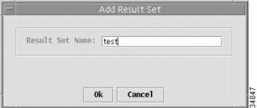
Step 4
The result set name is added to the window shown in Figure 4-9.
Step 5
Step 6
Step 7
The data that is entered in the four datawords, if any, is dependent on the result type. For detailed information on the content of the datawords, refer to the "Result Type Definitions" section.
Note
Adding an IN_TRIGGER Result Type for LNP
To add an IN_TRIGGER result type for LNP, complete the following steps:
Step 1
A window, similar to the one shown in Figure 4-6, is displayed.
Step 2
A window, similar to the one shown in Figure 4-9, is displayed.
Step 3
A dialog box, similar to the one shown in Figure 4-10, is displayed.
Step 4
The result set name is added to the window shown in Figure 4-9.
Step 5
A window, similar to the one shown in Figure 4-9, is displayed.
Step 6
Step 7
Step 8
For more information, see the "Adding a Default Result Set" section.
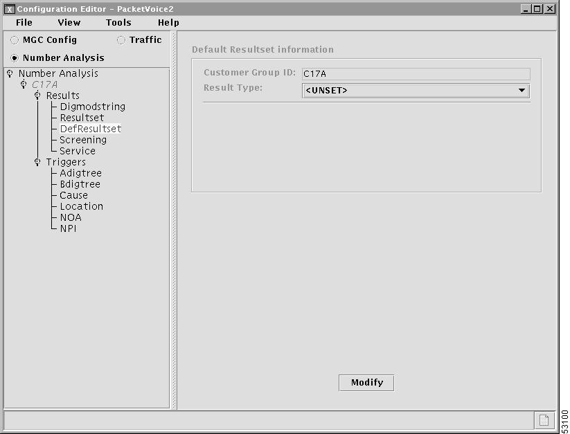
Adding a Default Result Set
The default result set is used in lieu of a specified result set at the end of call analysis.
To add a default result set, complete the following steps:
Step 1
A window, similar to the one shown in Figure 4-6, is displayed.
Step 2
A window, similar to the one shown in Figure 4-11, is displayed.
Step 3
•
–
–
–
–
•
–
•
–
Step 4
A window is displayed similar to the one shown in Figure 4-11.
Figure 4-11 Adding a Default Result Set
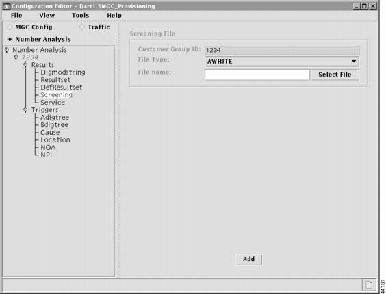
Adding a Screening File
Call screening is a type of analysis done on the A-number to determine if a call is accepted or rejected.
To add a Screening file, complete the following steps:
Step 1
A window, similar to the one shown in Figure 4-6, is displayed.
Step 2
A window, similar to the one shown in Figure 4-12 on the next page, is displayed.
Step 3
Step 4
Step 5
The Screening file is added to the hierarchical tree in the left-hand pane of the window.
Figure 4-12 Adding a Screening File
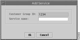
Adding a Service Name
Service names are defined to indicate the services that are available for screening purposes. A service name must be defined before a result type of Screening can be associated with a B-number.
To add a Service name, complete the following steps:
Step 1
A window, similar to the one shown in Figure 4-6, is displayed.
Step 2
Step 3
A window, similar to the one shown in Figure 4-13, is displayed.
Step 4
A dialog box, similar to the one shown in Figure 4-14, is displayed.
Step 5
A window with the Service name added, similar to the one shown in Figure 4-13, is displayed.
Figure 4-13 Adding a Service Name
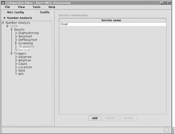
Figure 4-14 Defining a Service Name
Provisioning Triggers Components
The following sections describe the information you need to add to the Triggers components:
•
•
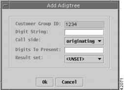
Adding an A Digit Tree
The Adigtree table is the number analysis table for calling numbers (A-numbers).
To add an Adigtree table, complete the following steps:
Step 1
A window, similar to the one shown in Figure 4-6, is displayed.
Step 2
A window, similar to the one shown in Figure 4-15, is displayed.
Figure 4-15 Adding an A Digit Tree

Step 3
A dialog box, similar to the one shown in Figure 4-16, is displayed.
Figure 4-16 Specifying Adigtree Data
Step 4
Step 5
Step 6
Step 7
Step 8
A window with the Adigtree table added, similar to the one shown in Figure 4-15, is displayed.
Adding a B Digit Tree
The Bdigtree table is the number analysis table for called numbers (B-numbers).
To add a Bdigtree table, complete the following steps:
Step 1
A window, similar to the one shown in Figure 4-6, is displayed.
Step 2
A window, similar to the one shown in Figure 4-17, is displayed.
Step 3
A dialog box, similar to the one shown in Figure 4-18, is displayed.
Step 4
Step 5
Step 6
Step 7
A window with the Bdigtree data added, similar to the one in Figure 4-17, is displayed.
Figure 4-17 Adding a B Digit Tree
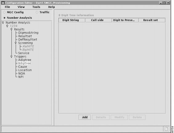
Figure 4-18 Specifying Bdigtree Data

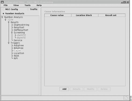
Adding Cause Codes
The cause table lists the cause codes generated when a call is rejected or cleared by the system. The cause for release can be from B-number analysis, cause analysis, or a failure generated during call processing.
To add Cause codes to the cause table, complete the following steps:
Step 1
A window, similar to the one shown in Figure 4-6, is displayed.
Step 2
A window, similar to the one shown in Figure 4-19, is displayed.
Figure 4-19 Adding Cause Codes
Step 3
A dialog box, similar to the one shown in Figure 4-20, is displayed.
Figure 4-20 Specifying Cause Codes
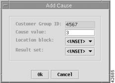
Step 4
Step 5
•
•
Step 6
A window with the cause information added, similar to the one shown in Figure 4-19, is displayed.
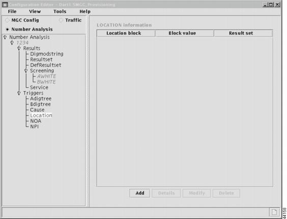
Adding a Location Table
The Location table is used to identify an associated result set. This table is accessed from the cause table through the location index. The location index is used to refer to a block of 16 entries in the Location table. The location value is used as an offset into a specified location block. You can associate an action with a specific entry in a Location table by entering a result set name in the location block at that point.
For detailed information on the Location table, refer to the "Location Table" section.
To add Location data, complete the following steps:
Step 1
A window, similar to the one shown in Figure 4-6, is displayed.
Step 2
A window, similar to the one shown in Figure 4-21, is displayed.
Figure 4-21 Adding a Location Table
Step 3
A dialog box, similar to the one shown in Figure 4-22, is displayed.
Figure 4-22 Defining Location Data
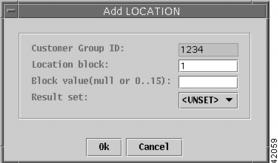
Step 4
Step 5
Step 6
A window with the location data added, similar to the one shown in Figure 4-21, is displayed.
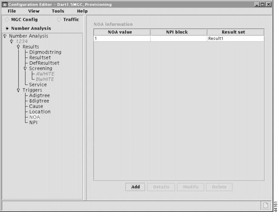
Adding a Nature of Address Table
The Nature of Address (NOA) table is used to define actions to be taken, based on the incoming NOA value. The NOA table includes two fields: the NPI index and the result set name. The NPI index value is used to indicate the offset into the unique NPI block. If the NPI index value is set to 0, no analysis is performed based on the NPI.
The result set name in the NOA table is used to associate a result set. If the result set name is set to 0, then no action is taken. It is possible to have only a result set name or only an NPI index value configured in the NOA table. If both the NPI index and the resultset name are set to 0, no analysis is performed.
For more information on creating the NOA table, refer to the "NOA and NPI Analysis" section.
To add a NOA table, complete the following steps:
Step 1
A window, similar to the one shown in Figure 4-6, is displayed.
Step 2
A window, similar to the one shown in Figure 4-23, is displayed.
Figure 4-23 Adding an NOA Table
Step 3
A dialog box, similar to the one shown in Figure 4-24, is displayed.
Figure 4-24 Defining NOA Values
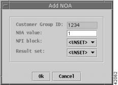
Step 4
Step 5
•
•
Step 6
A window with the NOA data added, similar to the one shown in Figure 4-23, is displayed.
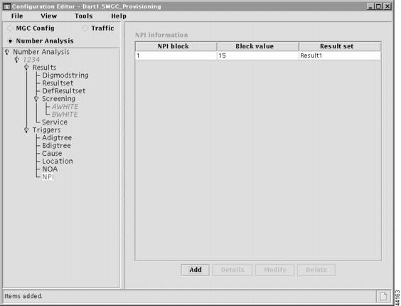
Adding a Numbering Plan Indicator Table
The Numbering Plan Indicator (NPI) table identifies an associated result set. The NPI table is accessed from the NOA table through the NPI index value. The NPI index refers to a specific block of 16 entries in the NPI table. The NPI value contained in the incoming IAM is an offset into the NPI block. An action is associated with a specific NPI value through the result set name at that location in the NPI block.
For detailed information on the NPI table, refer to the "NOA and NPI Analysis" section.
To add an NPI table, complete the following steps:
Step 1
A window, similar to the one shown in Figure 4-6, is displayed.
Step 2
A window, similar to the one shown in Figure 4-25, is displayed.
Figure 4-25 Adding an NPI Table
Step 3
A dialog box, similar to the one shown in Figure 4-26, is displayed.
Figure 4-26 Defining NPI Data
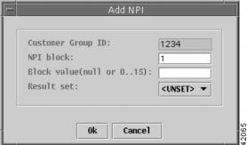
Step 4
Step 5
Step 6
A window with the NPI data added, similar to the one shown in Figure 4-25, is displayed.
Dial Plan Text File
After creating your dial plan, you can produce a dial plan text file containing all the MML commands for use as a batch file.
Before running the dial plan, verify that the following parameters are set in the properties.dat file. These parameters define the start indexes (first node) in the originating and terminating digit trees.
•
•
To use your dial plan, you must ensure that these two parameters are set as follows:
BOrigStartIndex = 1
BTermStartIndex = 2
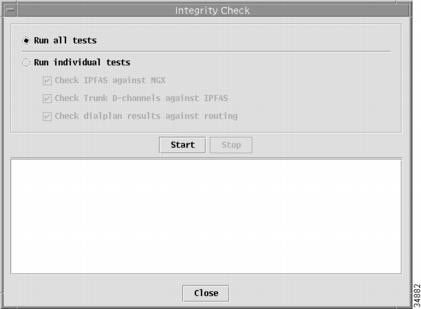
Performing an Integrity Check
You can also perform an integrity check of your dial plan against the routing plan to alert you to any configuration errors.
To perform an integrity check of your dial plan, complete the following steps:
Step 1
A dialog box, similar to the one shown in Figure 4-27, is displayed.
Figure 4-27 Integrity Check
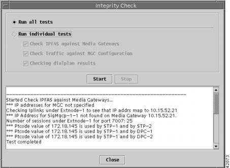
Step 2
When the tests finish, a dialog box similar to the one in Figure 4-28 is displayed.
Figure 4-28 Integrity Check Results
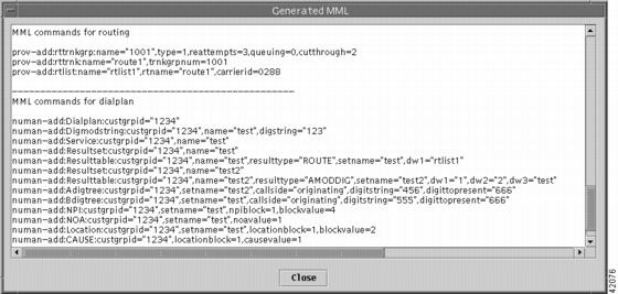
Viewing Generated MML
Viewing the generated MML allows you to scroll through the configuration to verify inputs, parameters, and defaults. To view the MML generated from your provisioning session, complete the following steps:
From the View menu, select MML. A dialog box with generated MML, similar to the one shown in Figure 4-29, is displayed.
Figure 4-29 Generated MML Commands
Deploying a New Dial Plan
When you finish defining your dial plan, you must deploy it to the Cisco MGC host.
To deploy a new dial plan, complete the following steps:
Step 1
A dialog box, similar to the one shown in Figure 4-30, is displayed.
Figure 4-30 Deploying a New Dial Plan
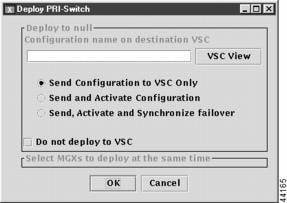
Step 2
You can click VSC View to browse the target Cisco MGC directories. This allows you avoid duplicating a dial plan name that might already exist.
Step 3
•
•
•
The dial plan is saved on the active host and copied to the standby host. To apply changes, you must restart the standby server after deployment.
 Feedback
Contact Cisco
- Open a Support Case

- (Requires a Cisco Service Contract)