Chapter 1. Dial Plan Overview
Available Languages
Table Of Contents
Dial Plan Overview
This chapter provides a comprehensive overview of the role that the dial plan plays in call processing. Dial plans enable the Cisco Media Gateway Controller (MGC), running the Cisco MGC software, to communicate with the Signaling System 7 (SS7) network and with the system components that control Cisco media gateways and bearer-traffic routing.
This chapter contains the following sections:
The dial plan provisioning processes described in this document apply to all solutions running Cisco MGC Software Release 7.4(x) and later.
Dial Plan Design
The dial plan design provides the basic functionality to meet customer requirements for calling and called number analysis. It also allows the creation of permutations of combined open and closed numbering plans, as well as the ability to easily modify them. The Cisco MGC dial plan design also provides the interface to a real time database.
The dial plan is, of necessity, the final step in provisioning the Cisco MGC node. To create a dial plan, you must first determine what routes, trunk groups, and trunks have been provisioned in the Cisco MGC. The provisioning information on the Cisco MGC provides a logical representation of the actual routes, trunk groups, and trunks on the Cisco media gateways that are controlled by the Cisco MGC.
The routing plan types developed during provisioning of the Cisco MGC determine which trunks in a media gateway are assigned to a specific trunk group and which trunk groups are assigned to which routes. The routes determine what originating and terminating points are serviced by the Cisco MGC.
With this information in hand, you can use the procedures detailed in this guide to create a dial plan specifying what types of service requests can be accommodated by the Cisco MGC, based on the call setup information, the calling number (A-number), the called number (B-number), and the routes, trunk groups, and trunks (individual circuits) available on the attached Cisco media gateways.

Note
For detailed information on the provisioning of the Cisco MGC, refer to the Cisco Media Gateway Controller Software Release 7 Provisioning Guide. For detailed information on provisioning the Cisco media gateways used in your solution, refer to the appropriate Solution Provisioning Guide.
Dial Plan Functions
The dial plan holds the key as to how each and every call that comes into the Cisco MGC is processed. Call processing rules that you establish in dial plans are static; however, the events and circumstances that determine how each call is ultimately processed are dynamic, and depend on a number of different factors both within and external to the Cisco MGC.
Before you can successfully build a dial plan, it is imperative that you understand the functions that the dial plan can perform. These functions are described in the following subsections:
Call Processing Functions
As calls arrive in the system, two telephone numbers and other data in the Initial Address Message (IAM) or the ISDN PRI setup message are processed to determine what call processing actions will be taken. Various actions can be implemented, such as call acceptance or rejection based on the calling or called number, what call control instructions are sent to the media gateways, and which egress trunk (or circuit) is ultimately selected to carry the call.
Using the dial plan that you create, the Cisco MGC performs the following functions:
•
The dial plan includes a list of all the numbers (digit strings) that require analysis, which is called a digit tree. The digit tree in which you enter a specific digit string is determined by whether the digit string is an originating number, which is entered in an A-digit tree, or a terminating number, which is entered in a B-digit tree.
Forwarded or redirected calls can also be subject to a screening feature that allows you to specify whether the calls are screened using the original calling party number (A-number) or the redirecting number.
•
Each branch under the A-number and B-number analysis trees represents a path used by the call-processing engine to process the calling or called number. You can also use the number analysis trees to perform digit modification. Digit insertion and removal permits digits to be removed and inserted in the B-number at any point in the process and at any point in B-number reception.
The dial plan also provides for backward information requests, which are required for specific protocol functionality, dependent on whether the protocol supports backward request messaging.
•
Result Set tables must be configured before the A-number and B-number digit trees are configured. You must create result sets for each type of analysis that you want the Cisco MGC to process. At a minimum, each result set requires at least one result type. Some result types require that other tables be configured first. For example, digit modification requires configuration of the digit modification trees before creation of the Result table. For a result type where a name or an index is required from another table, you must complete that table before you can complete the Result table.
A dial plan is a single file organized as a set of tables, each in a different section. The different sections are basically linked lists of values to be used after number analysis is completed. The dial plan can be changed dynamically at any time and the change will be effective with the next call that is processed.
The system must be able to handle multiple independent customer networks, each with its own set of digit trees, black lists and white lists, and other data. To accomplish this, all dial plan tables contain a CustGrpID field, which indicates the customer group for which a given database query applies.
Call Analysis
The processes by which the Cisco MGC analyzes and routes calls are illustrated in Figure 1-1. These processes depend on the information that is provisioned in the dial plan and the routing plan.
Figure 1-1 Cisco MGC Call Analysis and Routing Processes
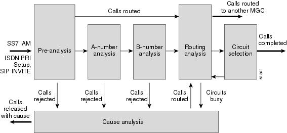
The calling number (A-number) and the called number (B-number) are contained in the ISDN User Part (ISUP) initial address message (IAM), which is included in the Signaling Information Field (SIF) of an SS7 Message Signal Unit (MSU), or in the ISDN PRI setup message, as shown on the left in Figure 1-1.
The IAM is just one part of the ISUP information that the Cisco Signaling Link Terminal (SLT) transmits to an associated Cisco MGC. In B-number pre-analysis, the called number (B-number) undergoes varying degrees of analysis, depending on other data in the IAM or the ISDN PRI setup message.
Call Routing
The ultimate objective of a dial plan is to establish a connection or circuit between the calling number (A-number) and the called number (B-number). There are three call routing terms that require definition to help you understand the information that follows.
•
•
•
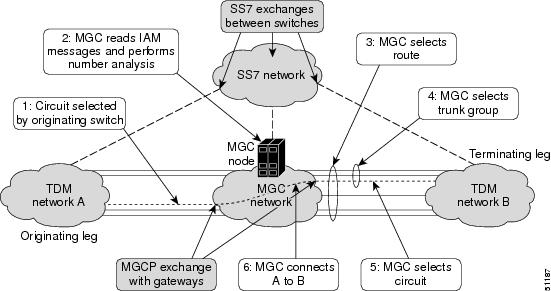
The dial plan is the primary determinant of how a call is routed from its origination to its termination through a Cisco MGC-controlled packet-switched network. Figure 1-2 is a simplified illustration of the sequence of events that occur in routing a call from its origination (TDM network A) to its termination (TDM network B).
Routing Functions
The routing functionality of the Cisco MGC includes the following, as illustrated in Figure 1-2.
•
•
•
however, it does not control the route taken within the packet network.•
The Cisco PGW 2200 supports the random distribution of calls across multiple trunk groups that belong to a particular route. The ability to turn random distribution on or off is supported on a route-by-route basis.
Note
Figure 1-2 Cisco MGC Call Routing Sequence
Call routing can be accomplished based on a number of factors, including the NOA value in the incoming IAM or Setup message or the combination of the NOA value and the incoming NPI value. If the routing is not determined solely on the basis of the B-number pre-analysis, then the B-number is formally analyzed. After formal B-number analysis is completed, routing analysis is performed based on the results of the B-number analysis.
Note
Once a route is chosen, the Cisco MGC selects a trunk group and an available trunk (circuit). If there is no available trunk, the Cisco MGC releases the call with a Cause Code that indicates all circuits are busy. As shown in Figure 1-1, calls can also be rejected at any point during analysis and released with an appropriate Cause Code, or routed to an announcement server that informs the caller of the reason the call could not be completed.
These are the basic call processing and routing functions of a dial plan. Creating a complete, efficient, and comprehensive dial plan requires thorough planning and some degree of foresight. Organization can simplify dial plan implementation.
Analysis
This section describes the various stages of analysis in some detail. When a call is received, normal call processing actions take place with regard to the protocol handling. The ingress trunk group (or sigpath) indicates the initial dial plan identity from data provisioned in the trunk group or sigpath files. Once the initial message is unpacked into the Call Context (CC), an internal signal is sent to the Universal Call Module (UCM), which sends the call to generic analysis to initiate pre-analysis.
The various types of analysis performed by Cisco MGC dial plans are described in the following subsections and illustrated in Figure 1-1
Pre-Analysis
The initial analysis request, made after the reception of an SS7 IAM or an ISDN PRI setup message, is called pre-analysis. Pre-analysis, if any, is performed according to the data in the received message. Pre-analysis provides you with the capability to perform NOA/NPI analysis as well as early analysis of the called number (B-number) to determine if it should be modified ("shaped") prior to formal analysis. The results from this stage of analysis are then returned to the UCM.
Pre-analysis can be divided into three actions, which occur in the following sequence:
NOA and NPI Analysis
Nature of Address (NOA) and Numbering Plan Indicator (NPI) analysis is performed based on the data provisioned in their respective tables and the NOA and NPI values contained in the incoming ISUP IAM or ISDN PRI setup messages. The incoming NOA and NPI values are protocol dependent.
Nature of Address Table
The NOA table is used to define the actions to be taken based on the NOA value in the incoming call. The two fields in the NOA table are the NPI Block and the result set name, as shown in Example 1-1.
•
–
–
•
–
–
A result set name can be configured in the NOA table only if you have an NPI Block value other than 0. If both the NPI Block value and the result set name are set to 0, no analysis is performed.
The following MML command was used to set up the NOA table with a CustGrpID of t001, an incoming NOA value of "3," an NPI Block value of "1," and a result set name (setname) value of "set3."
MML command numan_add:noa:custgrpid="t001",noavalue=3,npiblock=1,setname="set3"
Example 1-1 Nature of Address Table Example
Since the NPI Block value in row 3 of the NOA table is greater than zero (0), the result set name (setname="set3") in that row is used to determine the action taken.
Refer to "NOA and NPI Codes," for a list of the NOA codes for various protocol variants. Table C-2 in "Dial Plan Worksheets," can be used for planning your NOA table.
Numbering Plan Indicator Table
The NPI table is used to identify an associated Result Set Name, as shown in Example 1-2. The NPI table can have a number of blocks, each consisting of 16 entries (0 through 15). The specific block of 16 entries in the NPI table that is used is determined by the NPI Block value from the NOA table.
The NPI block value received in the incoming IAM or Setup message determines an offset into the designated NPI block. The result set name, if any, located at that offset into the designated NPI block is the result set to which the received NPI block value is mapped. The result types associated with this result set name determine what actions are associated with the incoming NPI block value.
There does not have to be an NPI table for every NOA entry, only when it is required because of a non-zero entry in the NPI Block column of the NOA table, as shown in Example 1-1.
The following MML command was used to set up the NPI table with a CustGrpID of "t001," an NPI block value of 1, a received NPI block value of 8, and a result set name of "set8."
Example 1-2 Numbering Plan Indicator Table Example
set1
set2
set3
set4
set5
set6
set7
set8
set9
set10
set11
set12
set13
set14
set15
set16
The result set name (setname="set8") specifies that the eighth row of the first block of the NPI table contains the result set name "set8." The result types included in result set name set8 determine the call processing actions to be performed, as described in the "Result Set Table" section.
If a block value is not specified in the MML command, all 16 entries (0 through 15) in the specified NPI block default to an empty result set name. so no action is performed.
Refer to "NOA and NPI Codes," for a list of the NPI codes for various protocol variants. Table C-3 in "Dial Plan Worksheets," can be used for planning your NPI table.
Early B-Number Analysis
At this later pre-analysis stage, B-digit tree analysis is actually being performed on the B-number digit tree. However, it is not considered part of formal analysis because this analysis is looking for only those result types that require a calling line identity (CLI). CLI result types are searched for because in certain locations it is possible to receive an IAM that does not have a CLI. When an IAM is encountered without a CLI, the CLI must be requested in a backward request message to the preceding switch.
Early B-number analysis also allows modification of the B-number digit string before formal analysis.
NANP B-Number Normalization
North American Numbering Plan (NANP) number normalization applies B-number normalization to intraLATA calls only for North American networks. B-number normalization is required only if the number plan analysis (NPA) property contains the 3-digit string providing the NPA prefix for the associated trunk group. If the NPA property is empty, then B-number normalization is not required.
If B-number normalization is required, the NPA property value for the trunk group is prepended as a 3-digit number to the 7-digit B-number (NXX-XXXX). This creates a 10-digit B-number in the format NPA-NXX-XXXX.
Formal Analysis
Once pre-analysis is completed and a valid response has been returned to the UCM, preparation of the channel on the originating channel controller (OCC) side is initiated by the UCM. Once this is complete and the OCC side is ready, the UCM makes the formal analysis request to invoke A-number analysis, followed by B-number analysis, and finally routing analysis.
Formal analysis provides full digit tree analysis of both the calling number (A-number) and the called number (B-number), if necessary, to determine (1) if further processing is required, and (2) if any resulting action must be taken after the number analysis is completed. The steps in processing are similar in each case, but the details might vary slightly.
Formal analysis of either the calling number or the called number can include any or all of the following:
•
A-Number Analysis
A-number analysis provides "digit by digit" analysis using the analysis tables, as well as call screening that supports both Blacklist and Whitelist screening capability.
From the point of view of the Cisco MGC, each digit arrives and is processed separately. Each digit is processed through a tree-structured representation that is stored in the digit tree table. Each digit tree allows analysis of the digits 0 through 9.
The data stored in the table for a particular digit includes a pointer to a record in the Result Set table. The Result Set table contains more details about the actions to be performed. Many different digit combinations can link to the same detailed record in the Result Set table.
A-number analysis provides the following specific capabilities:
•
•
•
•
•
•
B-Number Analysis
B-number analysis provides digit insertion and removal, number length determination, and vacant number identification. Digit insertion and removal permits digits to be removed and inserted at any point in the B-number and at any point in the process of B-number reception. Backward information requests are provided as required for specific protocol functionality, dependent on protocol support of backward request messaging. Also provided is the ability to return results such as cause codes, announcement identities (for routing to an announcement server), and route list names (as indexes into the routing process). Finally, B-number analysis is also capable of supporting both enbloc and overlap numbering schemes providing equivalent functionality to each mode.
B-number analysis provides the following specific capabilities:
•
•
•
•
•
•
•
•
•
•
•
•
•
Call Screening
Call screening is a type of analysis done on the calling number digit string to determine if the call is to be accepted or rejected, as shown in Table 1-1. Analysis of either the A-number or the B-number can trigger call screening; however, only the calling number (A-number) is screened.
The Cisco MGC software supports either white list or black list screening of the A-number:
•
•
The Cisco MGC software also supports either white list or black list screening of the B-number:
•
•
Table 1-1 Call Screening Actions
A- or B-number listed
Call completed
Call terminated
A- or B-number not listed
Call terminated
Call completed
Maintaining the Screening Database
Due to the nature and magnitude of the A-number/B-number whitelist and blacklist screening database, the screening files are usually not created by entering individual MML commands. The screening files can be created independently, then imported by using the MML command prov-add: files.
All of the whitelist and blacklist screening files can be populated using imported files. Screening files must all be placed in the /opt/CiscoMGC/etc/cust_specific directories and named as shown in Table 1-2.
Table 1-2 Call Screening Database Files
A-number
custgrpid.awhite
custgrpid.ablack
B-number
custgrpid.bwhite
custgrpid.bblack
A-Number File Formats
The file format for each entry in the A-number whitelist or blacklist screening files is the same:
<Type> <CallingPartyNumber>
where,
•
–
–
Additions and deletions can be commingled in the same file; however, the A-number whitelist and blacklist files must be maintained separately.
•
B-Number File Formats
The file format for each entry in the B-number whitelist or blacklist files is also the same:
<Type> <ServiceName> <CallingPartyNumber>
where,
•
–
–
Additions and deletions can be commingled in the same file; however, the B-number whitelist and blacklist files must be maintained separately.
•
•
MML Command
The format of the MML command to import both dial plan files and A-number and B-number whitelist and blacklist screening files is as follows:
prov-add:files:name=<file_format>, file=<file_name>, action=<file_action>
where,
•
–
–
–
–
–
•
–
–
–
–
–
•
Updating Screening Files
The screening database is designed to allow you to add and remove entries without opening a provisioning session. It also enables more than one user at a time to access the screening database. This capability is applicable to the Cisco PGW 2200 and the Cisco SC2200.
A provisioning session is not needed for individual MML commands; however, a provisioning session still needs to be opened when you are using the file import procedure described previously.
The target identifiers (TIDs) that are allowed without the opening of a provisioning session include:
•
•
•
•
Maximum File Sizes
The maximum number of ANI/CLIs that can reside in the A-number/B-number screening database depends on the Cisco MGC host platform. For Sun Microsystems Netra t112x hosts, the maximum number of entries is 500,000. For the Sun Netra 140x, the maximum is 1 million entries. It should be noted, however, that when the number of entries in the database approaches either maximum, it can have an adverse affect on the maximum number of sustained calls that can be supported.
White List Screening From the A-Digit Tree
Number screening is used to verify if a call can be completed. In the case of white list screening, the call is completed if the digit string is configured, or the call is terminated if the digit string is not configured. For an example of white list screening from the A-digit tree, see Figure 1-3.
In the dial plan, the digit string 301 was connected to the SCREENING result type from the A-digit tree. When the digit string was connected, it was associated with white list screening. When a customer dials with a calling number area code of 301, the calling number is screened to see if it is configured. In the white list example, the call is allowed through if the calling number is configured, or the call is terminated if it is not configured.
In this example, if the calling number is (301) 648-4444, the call is terminated because that number is not configured in the white list. However, if the calling number is (301) 648-5555, the call is connected because that number is configured in the white list.
Figure 1-3 White List Screening from the A-Digit Tree
Black List Screening From the A-Digit Tree
In the case of black list screening, the call is terminated if the digit string is configured in the list. The call is completed if the digit string is not configured in the list. For an example of black list screening from the A-digit tree, see Figure 1-4.
In the dial plan, the digit string 301 was connected to the SCREENING result type from the A-digit tree. While the digit string was connected, it was associated with black list screening. In this example, when a customer dials with a calling number area code of 301, the calling number is screened to see if it is configured. In the black list example, the call is terminated if the called number is configured in the black list, or the call is completed if it is not configured in the black list.
In this example, if the calling number is (301) 648-4444, the call is completed because that number is not configured in the black list. However, if the calling number is (301) 648-5555, the call is terminated because that number is configured in the black list.
Figure 1-4 Black List Screening from the A-Digit Tree

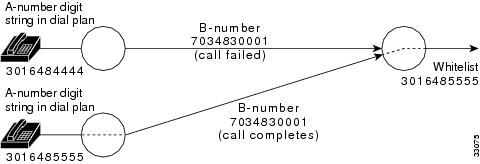
White List Screening From the B-Digit Tree
Number screening is used to verify if a call can be completed. In the case of white list screening, the call is completed if the called digit string is configured with a service and the calling number is associated with the same service in the screening table; otherwise, the call is terminated. For an example of white list screening from the B-digit tree, see Figure 1-5.
In the dial plan, the digit string 7034 was connected to the SCREENING result type from the B-digit tree. When the call is connected, it is associated with the Washington service and white list screening.
In this example, when a customer dials a number with 7034, the calling number (301) 648-4444 is screened and the call is terminated because the calling number is not configured in the white list for the Washington service. However, if the calling number were (301) 648-5555, the call would be connected because that number is configured in the white list for the Washington service.
Figure 1-5 White List Screening from the B-Digit Tree
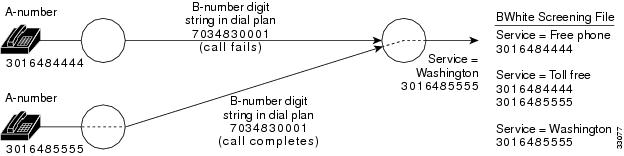
Black List Screening From the B-Digit Tree
In the case of black list screening, the call is terminated if the called digit string is configured with a service and the calling number is associated with the same service in the screening table; otherwise, the call is connected. For an example of black list screening from the B-digit tree, see Figure 1-6.
In the dial plan, the digit string 7034 was connected to the SCREENING result type from the B-digit tree. When the call is connected, it is associated with the Washington service and black list screening.
In this example, when a customer dials a number with the 7034, the calling number (301) 648-4444 is screened and the call is connected because the calling number is not in the black list for the Washington service. However, if the calling number were (301) 648-5555, the call would be terminated because that number is configured in the black list for the Washington service.
Figure 1-6 Black List Screening from the B-Digit Tree
Redirecting Number Screening

Caution
Redirecting number screening is designed to augment, not replace, screening of the original calling party number (A-number) by introducing screening of the redirecting number.
Redirecting number screening allows you to specify whether redirected calls are screened by using the original calling party number (A-number) or the redirecting number, which was originally the called party number (B-number) when the call was initiated, as illustrated in Figure 1-7.
Figure 1-7 Redirecting Number Screening
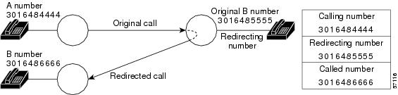
For redirected calls, the calling number parameter contains the A-number of the station that originated the call, the redirecting number parameter contains the calling number (A-number) of the station that redirected the call, and the called number parameter contains the new B-number of the station to which the call is redirected.
A-number screening for redirected calls can vary from customer to customer, so an office-based or switch-based parameter is required to specify which parameters are to be used for A-number screening. The XEConfigParm.dat file contains office-wide or switch-wide parameters in the Cisco MGC software, including the MDLANumberScreening parameter.
The default value of the MDLANumberScreening parameter is 0 (zero), which invokes the standard A-number screening on the number in the calling number parameter, regardless of whether the call is redirected or not. No screening is done on the number in the redirecting number parameter.
The redirecting number screening capability is enabled by setting the MDLANumberScreening parameter to a value of 1 (one) in the XEConfigParm.dat file.
Note
Depending on the type of analysis that invoked the original A-number screening, redirecting number screening makes it possible to screen either the original calling party number or the redirecting number.
•
•
a.
and
b.
Note
When redirecting number screening is activated, the initial address message (IAM) is returned to A-number screening where it is re-screened to determine whether the call can be completed based on the redirecting number instead of the original calling number. If the redirecting number can make calls to the new called party number (B-number), the call is completed.
If the result types digit modification (ADIGMOD or BDIGMOD) or number type (A_NUMBER_TYPE or B_NUMBER_TYPE) are encountered when a redirecting number is used during A-number analysis, no modification is performed on the redirecting number. In addition, the number analysis does not set the screening indicator field, because this field is not applicable for the redirecting number.
If a succeeding switch should determine that a redirected call is to be subjected to A-number screening, it uses the number contained in the redirecting number parameter in the A-number screening process.
Number Type Modification
Number type modification, or NOA modification, enables you to change the value of the incoming NOA, which may be required in certain international applications. This feature is designed for applications when a carrier is extending its services to new markets (usually in other countries), where local carriers might have different rules or formats for assigning NOA codes.
Number Modification
Number modification (ADIGMOD or BDIGMOD) can be used to add, delete, or modify specific digits of the calling number (A-number) or the called number (B-number) to support private dialing plans.
Result Analysis
Result analysis is not explicitly shown in any of the figures in this chapter; however, the result from reading the Cause table is either a Result Set Name or a Location Block, depending on whether the Cause table has been provisioned to read just the cause code or both the cause code and the location code.
•
•
For more detailed information on the Cause table, refer to the "Cause Table" section. For more detailed information on the Location table, refer to the "Location Table" section.
Before creating a Result table, you must create a Digit Modification table and a Service table. These two tables define additional parameter values that are used by the Result table. In addition, a route group must be created before the ROUTE result type can be defined.
Digit Modification Table
The Digit Modification table, Example 1-3, is used to define the digit modification string for a digit modification name. The digit modification string in the table is used to insert numbers into the calling number (A-number) or called number (B-number) at the application point specified in the AMODDIG or BMODDIG result type. Table C-4 in "Dial Plan Worksheets," can be copied and filled in to document the digit modification names and digit modification strings used in your dial plan.
The following MML command was used to set up the Digit Modification table with a CustGrpID of t001, a digit modification name of digmod3, and a digstring value of 703486.
Example 1-3 Digit Modification Table Example
Service Name Table
Example 1-4 is an example of a Service Name table. Table C-5 in "Dial Plan Worksheets," can be used to plan the Service Name table.
The following MML commands were used to create the Service Name table shown in Example 1-4.
MML command numan-add:service:custgrpid="t001",name="FreePhone"MML command numan-add:service:custgrpid="t001",name="TollLine"Example 1-4 Service Name Table Example
Result Table
The Result table, Table 1-3, lists all the result type names and their data words, which prescribe the actions that must be taken when the last analyzed digit in a digit string is reached. See the "Result Type Definitions" section following this table for definitions of result types and their associated data words.
Result Type Definitions
The following paragraphs contain definitions of the result types listed in Table 1-3
NONE
If this result type is received from an analysis, no action is required.
MORE_DIGITS_
REQUIREDThe DIG_REQD result type indicates that insufficient digits were received for analysis to provide a result with which call processing can be continued. This result type returns an indication to the call module of how many more digits are required for analysis to be completed by subtracting the number of digits returned in the analysis result type from the number of digits that have already been received.
Note
ROUTE
The ROUTE result type supplies a route list name, which is used as a starting index to the routing analysis process.
Note
INC_NUMBERING
The INC_NUMBERING result type returns information regarding the incoming trunk group side (OCC). This information sets the numbering criteria (overlap or en bloc) and the minimum and maximum numbers of digits permitted for that side.
•
1 = Open numbering (overlap)•
In the case of closed numbering (en bloc), these values should be equal.The data returned in this result type is used to overwrite default values loaded into the OCC at startup.
Note
AMODDIG
The AMODDIG and BMODDIG result types are for digit modification on the A-number or B-number,
BMODDIG
respectively. The capability exists to remove x digits from any point in either digit string and replace them with whatever digits are required. An example of this operation is as follows:
If we get result type 5 (BMODDIG) to modify the B-number, we receive the following datawords:
•
The range is from 1 through the total number of digits in the digit string (20 maximum).•
•
For example, if the application point is set to 1, then begin at the start of the digit string, remove 5 digits, and replace them with the digit string at the location specified by the modification index. After reading the digmodstrings table, the modification name gives a digit string to insert of 1321.
For example, if the application point = 1, the number of digits to remove = 5, and the modification name gives a result of 1321, then:
•
•
CAUSE
The CAUSE result type provides a release cause code as a result from analysis, which is then used in the release (REL) and cleardown messages as the call is cleared. The CAUSE result type provokes a negative result from analysis, and the cause is identified. Currently, the given cause value is passed into the cause analysis process and by table analysis the decision is made whether or not to:
1.
2.
3.
The cause code corresponds to any provisioned value that complies with the range of cause values permitted in call context. Refer to "Cause and Location Codes," for cause code values.
ANNOUNCEMENT
The ANNOUNCEMENT result type provides an announcement ID, local or remote indication, and route ID. These fields are defined as follows:
•
•
•
•
Note
CPC_REQ
The CPC_REQ result type indicates that the calling party category (CPC) has not been supplied and is required for the outgoing side.
CLI_REQ
The CLI_REQ result type indicates that the calling line identity (CLI) has not been supplied and is required for the outgoing side.
BSM_REQ
The BSM_REQ result type indicates that the basic service markings (BSM) have not been supplied and are required for the outgoing side.
FSM_REQ
The FSM_REQ result type indicates that the facility service markings (FSM) have not been supplied and are required for the outgoing side.
A_NUMBER_TYPE
The A_NUMBER_TYPE result type and B_NUMBER_TYPE result type (16) provide the capability
B_NUMBER_TYPE
to change the A-number type or B-number type NOA from that presented in the IAM or Setup message.
The value given as data in the result type (data word 1) will be the Cisco PGW 2200 internal call context value for the NOA relating to either the A-number or B-number.
The result is restricted to its analysis type, that is, the A-number type can only be changed in A-number analysis and the B-number type only in B-number analysis.
OTG_NUMBERING
The OTG_NUMBERING result type returns information regarding the outgoing trunk group side (Terminating Call Control). This information sets the numbering criteria (that is, overlap or en bloc), and the minimum and maximum permitted digits for that side.
•
•
BLACKLIST
The BLACKLIST result type provides the basic ability to screen A-numbers or B-numbers by digit tree analysis. If this result is received, the call is released with the cause value IC_BLACKLIST_CLI_ MATCHED (which may be changed by the protocol when sending the release message to the line).
The possible result types (screening criteria) and their application are as follows:
•
•
Note
•
•
CLI_NUMBER_LENGTH
The CLI_NUMBER_LENGTH result type basically indicates that the calling line identity has the incorrect number of digits. The Numbering Type field is not processed, but the maximum and minimum digit fields are used to determine if the CLI is too long or too short. If it is, a negative result is returned, the cause is set to IC_BLACKLIST_CLI_LENGTH_INVALID, and the call is released. Note that the protocol may apply a different cause code in the outgoing release message.
ROUTE_PREFERENCE
The ROUTE PREFERENCE result type delivers a result from A-number analysis. The data provided is set according to the Cisco PGW 2200 internal call context values for route preferences and is used during the routing process to bias the selection of trunk groups.
The possible values for route preference are as follows:
•
•
•
•
•
•
•
•
•
•
IN_TRIGGER
The IN_TRIGGER result type delivers a result from B-number analysis, which indicates that further analysis by an SCP is required due to an intelligent network (IN) call. The data provided identifies the service required (such as LNP) and, if necessary, an SCP/STP index for use when the TCAP call is made.
•
The valid Service Type values are as follows:
–
–
–
–
–
–
–
–
–
•
SCREENING
The SCREENING result type delivers a result from either A-number or B-number analysis indicating that a call must be made to the main memory database to carry out call screening on the A-number. Data word1 (screen type) identifies the type of screening that must be requested.
•
–
–
•
Examples of service name string values are "FreePhone,""800," and "900."
DATA_EXCHANGE
The DATA_EXCHANGE result type delivers a result from B-number analysis indicating that there are actions required to move certain data from one call context location to another. For example, if the result indicates a home-based local routing number (LRN), then the called party number and the generic address parameter (GAP) number must be exchanged, and new B-number analysis is invoked. The associated field, "ActionType," indicates the type of action that is required.
•
This number is a home LRN, that is, local to this Cisco MGC. This signifies that the Cisco MGC must complete the call to the dialed number contained in the GAP (not the number in the called party number). Consequently the GAP and called party numbers must be exchanged.
WHITELIST
The WHITELIST result type is returned from B-number analysis and signifies by table analysis that this number is valid and the call can proceed. No data words are used and any call processing action is implicit by the presence of the result type.
The absence of the WHITELIST result type invokes the default result type on a Cisco SC2200 signaling controller.
RTRN_START_ANAL
The RTRN_START_ANAL result type performs different actions depending on what stage of the analysis generates it:
•
•
Result Set Table
A Result Set table is a grouping of result types that can be associated with an A-digit tree, a B-digit tree, pre-analysis, or cause analysis. You can have only one result set for each digit string; however, you can have one or more result types in a result set. Each result set requires a unique name, and each result type within a result set also requires a unique name. However, the result type names do not need to be unique across result sets—it is the combination of result set name and result type name that must be unique. The result set name can be as many as 20 alphanumeric characters in length. The Result Set table is used only for configuration. Table C-6 in "Dial Plan Worksheets," can be used to plan your Result Set table.
Only one default result set is allowed. Creating a new default result type overwrites the previous default result type. Only one of the following result types is allowed for the default result set at any time:
•
•
•
When determining the result types for a result set, enter them in a logical order; for example, from screening to route. You can have as many intermediate analysis point result types in a result set as you want; however, once a result set has an endpoint analysis result type, that is the end of the result set.
Example 1-5 is an example of a Result Set table and the accompanying MML commands. The Result Set table lists the values that are included for each digit string in the table: Result Set Name, Result Name, Result Type, datawords 1 through 4, and the Next Result Name. The dataword values in the Result Set table are determined by the dataword values of the result type, as shown in Table 1-3.
In Example 1-5, the result name for result set1 is for the SCREENING result type. The value for dataword1 is 1, indicating whitelist screening will be performed on the first digit string. The value for dataword2 is also 1, which is an index for the Service Name table from which a service name can be obtained.
Note that two result types (A_NUMBER_TYPE and BLACKLIST) have been connected in Example 1-5 by using the same result set name (set4). When the MML session is run, the last result in a result set has to be created first. If the last result in a result set is not created first, an error is generated because a next result cannot be connected, because that result does not yet exist.
Example 1-5 Result Set Table Example
set1
result1
1
1
set2
result1
100
Washington
relist1
set3
result1
1
1
set4
result1
5
result2
set4
result2
1
set5
result1
0
1
digmod1
set6
result1
3
set7
result1
0
4
4
1 Click the result type to see the result type definition.
MML commands
The following MML commands were used to create the Result Set table in the example above.
numan-add:resulttable:custgrpid="t001",name="result1",resulttype="SCREENING",
dw1="1",dw2="Washington",setname="set1"
numan-add:resulttable:custgrpid="t001",name="result1",resulttype="ANNOUNCEMENT", dw1="100",dw2="1",dw3="rtlist1",setname="set2"numan-add:resulttable:custgrpid="t001",name="result1",resulttype="IN_TRIGGER", dw1="1",dw2="1",setname="set3"numan-add:resulttable:custgrpid="t001",name="result1",resulttype="A_NUMBER_TYPE", dw1="5",nextresult="result2",setname="set4"numan-add:resulttable:custgrpid="t001",name="result2",resulttype="BLACKLIST", dw1="1",setname="set4"numan-add:resulttable:custgrpid="t001",name="result1",resulttype="BMODDIG", dw1="1",dw2="1",dw3="digmod1",setname="set5"numan-add:resulttable:custgrpid="t001",name="result1",resulttype="B_NUMBER_TYPE", dw1="3",setname="set6"numan-add:resulttable:custgrpid="t001",name="result1",resulttype="INC_NUMBERING", dw1="0",dw2="4",dw3="4",setname="set7"Cause Analysis
Cause analysis is performed when a release (REL) message is received, or when a failure of some kind has occurred implying that the call must be released. The cause code value or the combined cause code and location code values from the Cause and Location tables are analyzed to provide a cause code that provokes rerouting of the call to another switch by the preceding switch, or rerouting of the call to an announcement server.
Cause Table
The Cause table lists the cause codes generated when a call is rejected or cleared by the system. The cause for release can be a result type (from either B-number analysis or cause analysis) or a failure (generated during call processing). The cause codes are used as the release message for internal causes.
The two fields in the Cause table are the Location Block and Result Set Name, as shown in Example 1-6.
•
If the value at the specified offset in the location block column is set to 0, no further analysis is performed based on the location.
•
If a result set name is not configured, then no action is taken.
A location block entry must be configured on the Cause table to have a result set name other than null (0). However, if both the location block and the result set name are set to null, no analysis is performed.
The following MML command was used to set up the Cause table with a CustGrpId of t001, a cause value of 3, a location block value of 1, and a result set name of "set3."
Example 1-6 Cause Table Example
Note
Refer to "Cause and Location Codes," for a list of the cause codes for the protocol variants. Table C-7 in "Dial Plan Worksheets," can be used to plan the Cause table.
Location Table
The Location table is used to identify an associated result set, as shown in Example 1-7. This table is accessed from the Cause table through the locationblock value. The locationblock value refers to a block of 16 entries (0 through 15) in the Location table. There can be multiple blocks in a Location table. The blockvalue specifies an offset into the specified location block. An action is associated with a specific blockvalue by associating the blockvalue with the result set name (setname) at the specified offset in the specified location block.
The following MML command was used to set up the Location table with a CustGrpID of t001, a locationblock of 1, a block value of 8, and a result set name of "set8."
Example 1-7 Location Table Example
set1
set2
set3
set4
set5
set6
set7
set8
set9
set10
set11
set12
set13
set14
set15
set16
Refer to "Cause and Location Codes," for a list of the location codes for the protocol variants. Table C-8 in "Dial Plan Worksheets," can be used to plan the Location table.
Routing Analysis
Routing analysis is started when pre-analysis, B-number analysis, or Cause analysis returns a route list name, which is used to access the Route List index as illustrated in Figure 1-8 The output from the Route List index is used to access the Route List table, from which the search for routes and trunk groups is started.
Route analysis and selection is based entirely on the trunk group data provisioned in the routing plan. Route preferences or bearer preferences present in the incoming IAM or Setup message are read and applied during the route selection process.
Note
The full B-number routing analysis capability can be applied to any trunk group the Cisco MGC handles (SS7 or ISDN PRI), a case in point being those telephony solutions where the Cisco PGW 2200 is functioning in an end-office capacity and switching to multiple PRI terminations. The ability to select between these multiple PRI terminations on full B-number analysis is provided, but with no requirement for a full B-number decode in the digit trees.
Figure 1-8 Routing Analysis and Selection

Note
The incoming NOA value (noavalue=3) in the MML command above is the offset into the NPI Block column of the NOA table. If the incoming NOA value is 3, then the value in that row of the NPI Block column (npiblock=1) determines whether analysis is performed in the NOA table.
The MML command above specifies the first block in the NPI table (npiblock=1), which consists of the Result Set Name column. The offset into the NPI block is specified by the NPI block value in the incoming IAM or Setup message (blockvalue=8).
 Feedback