System Architecture

Cisco HCS System Architecture

Cisco Hosted Collaboration Solution (HCS) is intended for both hosted and managed deployments. Cisco HCS delivers a full set of Cisco unified communications and collaboration services.

Cisco HCS optimizes data center (DC) environments, reducing the operation footprint of service provider (SP) environments. HCS provides tools to provision, manage, and monitor the entire architecture to deliver service in an automated way, assuring reliability and security throughout SP operations.

The Cisco HCS architecture consists of multiple functional network components. Each plays a specific role in the solution. Leveraging the framework provided by Cisco IP hardware and software products, Cisco HCS delivers unparalleled performance and capabilities to address current and emerging unified communications needs in the enterprise marketplace as a hosted managed-service offer.

The Cisco Unified Communications Services family of products optimizes functionality, reduces configuration and maintenance requirements, and interoperates with numerous applications. Cisco HCS provides these capabilities while maintaining high availability (HA), quality of service (QoS), and security.

The figure that follows provides a high-level view of Cisco HCS.

Figure 1. High-Level View of Cisco HCS

The rest of this guide describes the Cisco HCS architecture in more detail.

Functional Layers

Cisco Hosted Collaboration Solution is an end-to-end cloud-based collaboration architecture that, on a high level, may be distributed into the following functional layers:

  • Customer/customer-premises equipment (CPE) layer

  • UC infrastructure layer

  • Aggregation layer

  • Management layer

  • SP network/cloud layer

These layers, shown in Cisco HCS System Architecture as an overlay on the overall HCS Architecture. Each of these functional layers has a distinct purpose in HCS architecture, as described below.

Customer/Customer Premises Equipment Layer

The customer/customer premises equipment (CPE) layer provides connectivity to end devices (phones, mobile devices, local gateways, and so on). In addition to end user interfaces, this layer provides connectivity from the customer site to the provider's network.

UC Infrastructure Layer

Cisco Unified Computing System (UCS) hardware in the SP data center runs unified communications (UC) applications for multiple hosted business solutions. Virtualization, which enables multiple instances of an application to run on the same hardware, is highly leveraged so that UC application instances are dedicated for each hosted business. The ability to create new virtual machines dynamically allows the SP to add new hosted businesses on the same UCS hardware.

Telephony Aggregation Layer

The aggregation layer provides multiple options for interfaces to SIP trunking, Mobile, and IP Multimedia Subsystem (IMS) through a common aggregation node for multiple hosted businesses.

Management Layer

Management tools support easy service activation, interoperability with existing SP OSS, and other management activities including service fulfillment and assurance.

SP Cloud Layer

The SP cloud layer leverages existing services in the SP network such as PSTN and regulatory functions. In the Cisco HCS system architecture, the UC infrastructure components are deployed as single tenants (dedicated per customer) in the cloud. These dedicated components and other management components run on virtual machines running on UCS hardware.

HCS Data Center Architecture and Components

HCS data center design delivers a flexible, optimal data center solution that can easily scale to a large number of physical and virtual servers. The design supports network virtualization to separate customers while including virtualized network services, such as virtual firewalls.

The HCS data center architecture leverages the UCS platform aggregated into the data center core and aggregation switches. The architecture is based on a standard layered approach to improve scalability, performance, flexibility, resiliency, and maintenance.

Solution Architecture

The solution is optimized toward data center environments to reduce the operation footprints of service provider environments. It provides a set of tools to provision, manage, and monitor the entire architecture to deliver an automated service that assures reliability and security throughout the data center operations.

Architecture Considerations and Layers

Cisco HCS System Architecture gives an overview of the HCS Architecture and the placement of the Data Center UC infrastructure layer and its connectivity to the rest of the layers.

  • Customer/CPE Layer: This layer provides the connectivity to the end devices that includes phones, mobile devices, and local gateways. In addition to the end user interfaces, this layer provides connectivity from the customer site to the provider's network

  • UC infrastructure layer: The UC infrastructure layer is constructed around the HCS data center design to provide a highly scalable, reliable, cost effective, and secure environment to host multiple HCS customers that meet the unique SLA requirements for each application/customer.

    In this architecture, the UC layer services components (such as Unified Communications Manager, Cisco Unity Connection, the Management layer, and IM and Presence Service) are deployed as a single tenant (dedicated per customer) in the cloud on the multi-tenant UC infrastructure. Expressway-E and Expressway-C provide secure signaling and media paths through the firewalls into the enterprise for the key protocols identified. The hardware is shared using the virtualization among many enterprises and the software (applications) is dedicated per customer. Expressway is used for secure access into the enterprise from the internet as opposed to other access methods (MPLS VPN, IPSEC, Anyconnect, and so on.)

  • Telephony Aggregation Layer: This layer is required in a Cisco HCS deployment to aggregate all the HCS customers at a higher layer to centralize the routing decision for all the off-net and inter-enterprise communication. A session border controller (SBC) in the aggregation layer functions as a media and signaling anchoring device. In this layer, the SBC functions as a Cisco HCS demarcation that normalizes all communication between Cisco HCS and the external network, either a different IP network or the IP Multimedia Subsystem (IMS) cloud.

Data Center Deployment Concepts

Points of Delivery

Cisco cloud architecture is designed around a set of modular data center (DC) components that consist of building blocks of resources called "Points of Delivery" (PoDs). PoDs are comprised of shared resource pools of network, storage, and compute. Each of these components is virtualized and used by multiple customers securely, so that each cloud customer appears to have its own set of physical resources.

This modular architecture provides a predictable set of resource characteristics (network, compute, and storage resource pools, power, and space consumption) per unit that are added repeatedly as needed. For this discussion, the aggregation layer switch-pair, services layer nodes, and one or more integrated computer stacks are contained within a PoD.

In Cisco HCS, there are several scales of data center PoDs, including the following:

  • Large PoD - suitable for an deployment with a higher number of customers, with customers either large or small in size

  • Small PoD - suitable for small-to-medium business environments of less than 80 customers

For more information, refer to the following documents:

  • Cisco Hosted Collaboration Solution Release 11.5/12/5 Capacity Planning Guide
  • Cisco Hosted Collaboration Solution Release 11.5 End to End Planning Guide

Small Medium Business Solutions

The classic Service Provider Service Provider Cisco HCS Data Center infrastructure model includes Nexus 7000 switches, SAN, UCS with B-series blade servers, a session border controller (SBC), and so on, that support a large number of end users across a high number of customers. This involves considerable initial cost and is suitable for large service providers.

For service providers with less than 940 tenants or shared clusters, there are a number of ways that you can deploy the data center infrastructure using smaller hardware components and shared application models to optimize scale and cost. You can deploy the Cisco HCS small/medium business solution on any of the data center infrastructure models.

Deployment Comparison HCS

Review the following table to see a comparison of the different options available for each deployment model.

Table 1. Comparison—Data Center Infrastructure Models
Function or Product Large PoD Small PoD
Number of tenants*** Up to 940 Approximately 80
Note 
Storage switches such as Cisco MDS 9000 switches are optional and aren't required for Small PoD deployments.
Aggregation Nexus 7000, Nexus 9396, Nexus 9508 Nexus 5500
Cisco Unified Compute System (UCS) UCS with B-series blades UCS with B-series blades
Storage Fabric interconnect, SAN or NAS storage Fabric interconnect, SAN or NAS storage
Media/Signaling Anchoring Device (Multi-VRF-Enabled for Multiple customers)
Security ASA 5585-X ASA 5555-X
(Optional) Site-to-Site VPN Concentrator SBC SBC
(Optional) Line Side Access SBC SBC
(Optional) Shared Cisco Expressway for Business to Business Dialing with Non HCS Enterprises over Internet Expressway-C and Expressway-E on UCS B-series Expressway-C and Expressway-E on UCS B-series
(Optional) Cisco Expressway Expressway-C and Expressway-E on UCS B-series Expressway-C and Expressway-E on UCS B-series
Cisco Prime Collaboration Assurance available Yes Yes
(Optional) Dedicated Instance Yes Yes
(Optional) OTT Remote Access with Expressway Yes Yes
(Optional) Shared RMS with Expressway Yes Yes
(Optional) Jabber Guest Yes Yes
(Optional) Cisco Webex CCA Yes Yes
(Optional) Business to Business Video through Shared Expressway Yes Yes

Dedicated Instance

The Service Provider Cisco HCS Data Center infrastructure model includes Nexus 7000 switches, SAN disks, UCS with B-series blades, and a supported Session Border Controller (SBC), which support a large number of end users across a high number of customers. This infrastructure model involves considerable initial cost and is suitable for large service providers.

For service providers with fewer than 940 customers, there are a number of ways that you can deploy the data center infrastructure using to optimize scale and cost. You can deploy Cisco HCS on either of the data center infrastructure models: Large PoD or Small PoD.

Dedicated instance refers to the model of applications where there is a separate application instance (Cisco Unified Communications Manager) for each customer. In one C-series server there can be different customer instances based on how applications are distributed in the server. Any reference to a UC application such as Unified Communications Manager, Unified Communications Manager IM and Presence, Cisco Unity Connection, Cisco Emergency Responder, and CUAC, that does not include "Shared" or "Partitioned" as part of the title implies that it is a dedicated instance.

Partitioned Unity Connection

To help the Cisco HCS solution scale more customers on the same hardware, you can partition a single Cisco Unity Connection instance to support multiple customer domains.

Cisco Unity Connection exposes the configuration and provisioning to support multiple customers by REST APIs. The Cisco HCS service fulfillment layer uses the partitioned Unity Connection REST APIs to allow Cisco HCS service providers to configure and provision customers into the partitioned Unity Connection.

Cisco HCS continues to support the dedicated Cisco Unity Connection in addition to the new partitioned instance. Partitioned Unity Connection is not a new product with a new SKU. The HCS administrator and domain managers must decide the role of Unity Connection as either regular or partitioned.


Note

The cluster limit for Unified CM and IM/P is one. For more information on Partitioned Unity Connection, see the documentation as follows:
  • Use Cisco Unified Communications Domain Manager to provision partitioned Cisco Unity Connection if you are running version Cisco Unified Communications Domain Manager 10.6(1).

Data Center Design for Large PoD


Note

The information in this section applies to all data center infrastructure deployment models; any differences are noted in Data Center Design for Small PoD.


Within the data center backbone, the Large PoD design provides the option to scale up the available network bandwidth by leveraging port-channel technology between the different layers. With Virtual Port Channels (vPC) , it also offers multipathing and node/link redundancy without blocking any links.

When they deploy the Cisco HCS Large PoD solution, service providers require isolation at a per-customer level. Unique resources can be assigned to each customer. These resources can include different policies, pools, and quality of service definitions.

Virtualization at different layers of a network allows for logical isolation without dedicating physical resources to each customer; some of the isolation features are as follows:

  • VRF-Lite provides aggregation of customer traffic at Layer 3

  • Multicontext ASA configuration provides dedicated firewall service context for each of the customers

  • VLAN provides Layer 2 segregation all the way to the VM level

To support complete segregation of all the Cisco HCS customers, Cisco recommends that you have separate Virtual Routing and Forwarding (VRF) entries for each Cisco HCS customer. Each customer is assigned a VRF identity. VRF information is carried across all the hops within a Layer 3 domain, and then is mapped into a one or more VLANs within a Layer 2 domain. Communication between VRFs is not allowed by default for privacy protection of each customer. The multimedia communication between customers is allowed only through the Session Border Controller (SBC).

The following figure shows the Cisco HCS Solution architecture with all the data center components for a Large PoD deployment. For more information on the Small PoD deployment architecture, refer to Small PoD Architecture.

Figure 2. Physical Data Center Deployment for Large PoD


Nexus 7000 switches are used as the aggregation switches and there is no core layer within the Service Provider Cisco HCS Data Center. The aggregation device has Layer 3 northbound and Layer 2 southbound traffic.

In the Cisco HCS Large PoD architecture, it is assumed that the VRF for each customer terminates at the MPLS PE level and runs the VRF-lite between the PE and the Nexus 7000 aggregation. In this case, the Nexus 7000 acts as a CE router from the MPLS cloud perspective.

Data Center Aggregation Layer

The current recommended Cisco HCS Large PoD deployment deploys a pair of Nexus 7000 switches which serve as the aggregation layer switches. In this model, there is no core layer, only an aggregation layer which serves as the Layer 3 and Layer 2 termination point. The pair of Nexus 7000 switches connect Layer 3 northbound to the MPLS PE routers, and southbound to either fabric interconnect or a Nexus 5000 switch at Layer 2, depending on the scale of the deployment.

In this configuration it is not necessary to define separate VDCs, therefore resources such as VLANs, VRFs, HSRP groups, BGP peers, and so on, are available at the chassis level.

For more details on components in the aggregation layer, see Aggregation System Architecture.

Access-to-Aggregation Connectivity

Access-layer devices are dual-homed to the aggregation pair of switches for redundancy. When spanning-tree protocol is used in this design, there is Layer 2 loop and one of the uplinks is in blocking mode. This limits the bandwidth to half if multiple links are deployed between the access and the aggregation layers. These uplinks are configured as trunks to forward multiple VLANs. Based on spanning-tree root existence of each VLAN and if these VLANs are load-balanced across multiple aggregation switches, some VLANs are active on one link and the rest of the VLANs are active on the second link. This provides a way to achieve some level of load-balancing. However this design is complex and involves administrative overhead of configuration.

We recommend that you use the virtual port channel. This allows you to create a Layer 2 port channel interface distributed across two different physical switches. Logically it is one port-channel. Virtual port channels interoperate with STP to provide a loop free topology. The best practices to achieve that is to make the 7000 aggregation layer the logical root, assign same priority for all instances in both 7000 and configure peer switch feature. For more information about best practices see http://www.cisco.com/c/dam/en/us/td/docs/switches/datacenter/sw/design/vpc_design/vpc_best_practices_design_guide.pdf

Data Center UCS and Access Layer

The access layer provides physical access to the UCS compute infrastructure and connectivity to the storage area network (SAN) arrays.

Fiber Channel is recommended for SAN connectivity. Connectivity between the UCS 6200 series access layer switches and UCS blade server chassis is based on 10 Gbps Fiber Channel over Ethernet links, which carry Ethernet data traffic and Fiber Channel storage traffic. The network components in this layer include Cisco 6200 Fabric Interconnects and Nexus 1000v.

Prerequisite and Components

The data center access layer includes the fabric interconnect components for your design. You should set up the following before you implement UCS and the fabric interconnect:

  • IP infrastructure as described in Implementing Service Provider IP Infrastructure.

  • UCS Chassis Basic physical setup, cabling and connectivity.

  • Cisco Fabric Interconnect HA Cluster setup.

  • Connectivity to Cisco Unified Computing System Manager (UCSM).

HCS on FlexPoD

FlexPoD is a predesigned base configuration that is built on the Cisco Unified Computing System (UCS), Cisco Nexus data center switches, and NetApp Fabric-Attached Storage (FAS) components and includes a range of software partners. FlexPoD can scale up for greater performance and capacity or it can scale out for environments that need consistent, multiple deployments. FlexPoD is a baseline configuration, but also has the flexibility to be sized and optimized to accommodate many different use cases.

Cisco and NetApp have developed FlexPoD as a platform that can address current virtualization needs and simplify data center evolution to IT as a Service (ITaaS) infrastructure. Cisco and NetApp have provided documentation for best practices for building the FlexPoD shared infrastructure stack. As part of the FlexPoD offering, Cisco and NetApp designed a reference architecture. Each customer's FlexPoD system may vary in its exact configuration. Once a FlexPoD unit is built it can easily be scaled as requirements and demand change. This includes scaling both up (adding additional resources within a FlexPoD unit) and out (adding additional FlexPoD units).

For more detailed information about FlexPoD, click the following link: http://www.cisco.com/en/US/netsol/ns1137/index.html.

Service Insertion

Integration of network services such as firewall capabilities and server load balancing is a critical component of designing the data center architecture. The aggregation layer is a common location for integration of these services since it typically provides the boundary between Layer 2 and Layer 3 in the data center and allows service devices to be shared across multiple access layer switches. The Nexus 7000 Series does not currently support services modules.

For HCS data center architecture, Cisco Adaptive Security Appliance (ASA) is recommended for firewall services. The ASA can be deployed in Layer 2 or Layer 3 multicontext mode depending on the requirement of the service provider.

As an example, if a service provider wants to terminate the VPN at the ASA security appliance, the ASA has to be deployed in Layer 3 mode, because Layer 2 mode does not support the VPN termination. The service provider can specify the customer VLANs that need to go through the ASA for security purposes; the rest of the traffic will not go through the ASA security appliance.

Storage Integration

Another important factor changing the landscape of the data center access layer is the convergence of storage and IP data traffic onto a common physical infrastructure, referred to as a unified fabric. The unified fabric architecture offers cost savings in multiple areas including server adapters, rack space, power, cooling, and cabling. The Cisco Nexus family of switches spearheads this convergence of storage and data traffic through support of Fiber Channel over Ethernet (FCoE) switching in conjunction with high-density 10-Gigabit Ethernet interfaces. Server nodes may be deployed with converged network adapters that support both IP data and FCoE storage traffic, allowing the server to use a single set of cabling and a common network interface.

Note that the Cisco Nexus family of switches also supports direct LUN connectivity to SAN storage using FC connectivity. With licensing, the ports can be fiber channel switched directly to an external storage array.

The Fabric Interconnect connects the Cisco HCS platform to the storage network using the MDS 9000 series switches with multiple physical links (fiber channel) for high availability. In Cisco HCS deployment of the data center, all the link connections between any components are deployed in a redundant mode to provide high level of resilience.

Traffic Patterns and Bandwidth Requirements for Cisco HCS

This section provides basic guidelines on bandwidth capacity for UC applications.

Figure 3. Traffic Flow Patterns in Cisco HCS

Data Center Bandwidth Capacity


Note

This section applies to HCS Large PoD deployments only.


  • These numbers are best estimates based on the UC applications only.

  • The numbers may change if some other applications or data traffic is included, for example, IVR.

  • Bandwidth capacity is strictly based on the traffic coming into the DC.

  • You may need to configure QoS for voice traffic to make sure other data traffic does not use the bandwidth.

  • The bandwidth requirement within the data center for the UC application is not high, because only signaling traffic gets into the data center.

  • The main bandwidth issue may occur at the core IP network level and at the SBC level, which does the media anchoring outside of the data center.

  • Based on the table below:

    • 10,000 users requires 283 Mbps

    • 50,000 users requires 1.415 Gbps

  • Eight-port 10GE module on Nexus 7000.

  • Each 10GE port potentially supports up to 350,000 user signaling traffic.

Note

This table provides a basic guideline for deploying UC on UCS.


Table 2. Bandwidth Usage for UC Applications on UCS Hardware
Numbers of Phones (Subscribers) BHCA (Calls per Phone per Hour) Bandwidth SP Control Traffic with Encryption Total Bandwidth
1000 phones 10 619 bps (includes register type messages and call-specific data) 619 kbps Approximately 0.62 Mbps
10% phones using voicemail 2 91.56 Kbps (6.711 codec) 9156 Kbps Approximately 9.2 Mbps
10% phones using MOH service (software base) 1 91.56 Kbps (6.711 codec) 9156 Kbps Approximately 9.2 Mbps
5 contact center phones 30 1.53 Kbps 7.695 Kbps
10% phones using shared line 4 343 bps 34.3 Kbps

Data Center Design for Small PoD

The architecture described in this section is referred to as the Cisco Hosted Collaboration Solution (HCS) Small Point of Delivery (PoD). The Small PoD is designed to support up to 45 customers, and enables you to deploy and offer Cisco HCS with a lower entry-level cost than the traditional Cisco HCS Large PoD.

With the Small PoD, you can:

  • Start offering HCS with minimal investment

  • Expand the HCS offering across data centers with minimal investment at a location close to the Point of Delivery

Although this section discusses the options to scale either horizontally or by migration to a Large PoD, each design has its own pros and cons. You must perform the necessary due diligence concerning the scale and growth needed before you decide on the Small PoD option.

Refer to the Cisco Hosted Collaboration Solution Compatibility Matrix for a list of Small PoD hardware components.

The sections that follow discuss the details of the Small PoD model and its impacts such as scale, performance and reliability.

Small PoD Architecture

The Cisco Hosted Collaboration Solution (HCS) Small PoD architecture design includes layering and partitioning the compute, network, storage, and services layer.

The following figure shows the compute layer, which consists of one to four Cisco Unified Computing System (UCS) chassis connected through the Fabric Interconnect (FI) to the Nexus switches that are equipped with Layer 3 functionality. Use the Nexus switch at the aggregation layer to provide northbound connectivity to the WAN Edge/MPLS Provider Edge (PE) router.

Figure 4. HCS Small PoD Physical Network


The complete system as shown in the figure is a single PoD that connects to the WAN Edge/MPLS Provider Edge (PE) router. You can connect multiple PoDs to the WAN Edge/MPLS PE router as long as you address the bandwidth requirements of each PoD. For more information, refer to Traffic Patterns and Bandwidth Requirements for Cisco HCS.

The Cisco Adaptive Security Appliance (ASA), which provides virtual firewalls for every customer using firewall contexts, provides the perimeter security for the HCS customers. The ASA connects to the Nexus 5548UP in a redundant manner to provide availability during failures. To provide redundancy, configure vPC links on Nexus 5000 and the ether channels on the ASA.

To support site-to-site Virtual Private Networks (VPN), use the Cisco ASR 1000 Series Aggregation Services Router (ASR) as the Site-to-Site VPN Concentrator. The ASR 1000 is configured for Virtual Routing and Forwarding (VRF) aware VPN to support the VPN tunnels from the customer premises.

You can use a third-party SBC to aggregate the traffic to and from the public switched telephone network (PSTN) and inter-customer traffic.

The key elements for a Small PoD deployment are as follows:

  1. The UCS 5108 chassis configuration uses the same configuration as a standard HCS deployment that is equipped with B-Series half-width servers (as recommended for Cisco HCS).

  2. Each FI in the FI pair are connected with two links from each UCS 5108 chassis.

  3. One option is to directly connect the storage to the FIs with virtual SANs (VSANs) distributed across the two FIs if the version of the UCS is 2.1 or above. The two links between each FI and redundant storage processors on the storage system provide high availability during failures. This deployment does not require MDS switches and assumes the 2.1 and later versions for FI. For more information, refer to the UCS Direct Attached Storage and FC Zoning Configuration Example, available at http://www.cisco.com/en/US/products/ps11350/products_configuration_example09186a0080c0a508.shtml. The recommended connectivity configuration uses an MDS 9200, 9500 or 9700 series with security and encryption enabled.

  4. You can also connect the storage at the Nexus 5548 switches, if the version of the Cisco UCS Manager (pre 2.1) that is deployed does not support direct connectivity from the FI without a switch.

  5. Equip the Nexus 5000 with a Layer 3 Daughter Card to configure Layer 3 functionality. The access and aggregation layer functions are collapsed into the Nexus 5000 pair in this deployment.

  6. Configure the Nexus 5000 in the aggregation layer using the Large PoD configuration, which includes the following configuration:

    • Border Gateway Protocol (BGP) toward the PE for each customer

    • North and south VRF for each customer

    • North and south HSRP instances for each customer, along with static routes

  7. Connect the Adaptive Security Appliance (ASA) to the Nexus 5000 at the aggregation level, as in the Cisco HCS Large PoD environment.

  8. If centralized PSTN routing is needed, deploy an SBC for centralized call aggregation as in a Cisco HCS Large PoD deployment.

  9. Attach Customer Premises Equipment (CPE) devices to the PE for MPLS VPN between the customer premises and the data center.

  10. To support Local Breakout (LBO), use an Integrated Services Router (ISR) G2 Series. The same equipment can be used as a CPE.

  11. If you deploy Small PoDs geographically across data centers, you must meet the delay requirements as specified for Clustering Over the WAN (CoW).

  12. Backup and restore is performed using standard Cisco HCS procedures. Refer to the Cisco Hosted Collaboration Solution Maintain and Operate Guide.

The following figure shows the HCS Small PoD system architecture from a logical topology perspective. The Nexus 5000 Aggregation node is split logically into a north VRF and a south VRF for each customer. A Layer 3 (L3) firewall context (on ASA 5555-X) is inserted in the routed mode to provide perimeter firewall services.

In the figure, an SBC is used to interconnect to the PSTN. It also provides logical separation for each customer within the same box using VRFs/VLANs and adjacency features.

Figure 5. HCS Small PoD Logical Network

Small Pod Deployment Models

The following figure shows the Small PoD deployment with an SBC.

Figure 6. HCS Small PoD with an SBC


This figure shows the storage connection with two options. The solid line FC connections are for direct storage connection at the FI. The dashed FC connections are for storage connection at the Nexus 5500 or 5600, depending on which is being used in the deployment. The additional FC links between the FI and Nexus to carry the storage traffic from the FI to the Storage System are also shown. Other options using FCOE are possible but not covered in this document.

Similar to the Large PoD deployment, the Small PoD deployment model uses the ASR 1000 as the Site-to-Site VPN Concentrator to connect customers over the internet.

With the Small PoD deployment, service providers can still deploy multiple data centers and deploy clustering over WAN for all the Unified Communications (UC) applications to support geo-redundancy. To accomplish this, deploy a Small PoD in multiple data centers, or deploy a Small PoD in one data center and a Large PoD in the other data center. Follow the standard HCS disaster recovery procedures as recommended.

Small PoD Redundancy

For a Small PoD deployment, redundancy of the system is the same as redundancy for the HCS Large PoD. Redundancy includes applications using CoW, redundant security appliances (ASA), redundant Site-to-Site VPN concentrators, network components (redundant Nexus 5000), blade servers, fabric interconnect, virtual Port Channels (vPC), and physical link level redundancy.

You must deploy an SBC in redundant active/standby mode for box-to-box redundancy as recommended in standard HCS documentation.

Options for Storage Connectivity

This design proposes two options for storage connectivity. It highlights the pros and cons of each option and the applicability to the small deployment in HCS.

  1. Storage connection option—F1 to storage direct attach

    The Cisco UCS 2.1 FI supports direct connection of the storage systems, which simplifies the configuration and connectivity for HCS Small PoD deployment. If the version of the UCS firmware is 2.1 or above, attach the storage directly at the FI without the use of fabric switches.

    The direct connectivity can be either Fiber Channel over Ethernet (FCoE) or Fiber Channel (FC) depending on the support on the storage system.

    Pros:
    • Avoids an extra hop to the storage and improves latency

    • Removes the need for additional license on Nexus 5000 for storage connectivity

    • Reduces port consumption

    • Reduces cabling between F1 and Nexus 5000

    • Simplifies configuration on Nexus 5000

    • Makes Nexus 5000 resources available for data traffic

    • Provides the option to connect NAS to FI using appliance ports

    Cons:
    • Cannot extend storage beyond a single pair of FI. However, since Small PoD deployment does not span more than one FI pair, this disadvantage does not impact Small PoD deployment.

  2. Storage connection option—Storage connected at Nexus 5000

    Attach the storage to the Nexus 5548 switches as shown in Small PoD Architecture (dashes lines). If firmware 2.1 series is installed and is to be used on the FI, attaching the storage directly to the FI is an option. Connect additional links for Fiber Channel over Ethernet (FCoE) or use Fiber Channel (FC) links between FI and Nexus 5000 to handle the storage traffic.

    Pros:
    • Storage can be shared across FI pairs. This is not a requirement in Small PoD deployments.

    Cons:
    • Requires extra hop to the storage and impacts latency

    • Requires additional license on Nexus 5000 for storage connectivity

    • Increases port consumption

    • Increases cabling between Fi and Nexus 5000

    • Increases configuration on Nexus 5000

    • Shares Nexus 5000 resources to handle storage and data traffic

Small PoD Storage Setup

When you deploy the Cisco HCS Small PoD, Cisco recommends that you use the local SAN storage. The SAN storage can be from a UCS approved vendor, if it supports the IOPs specified for UC applications.

PSTN Connectivity to Small PoD

If you require centralized breakout, deploy either a centralized SBC or a dedicated SBC for each customer.

Small PoD Layer 2 Scale

Efficiency of resource utilization and multi-customer solutions are directly dependent on the amount of virtualization implemented in a data center. Scale of the VMs drives the scale requirement of the network components in terms of port densities and Layer 2 (L2) capacity. The key resources that define at L2 scale are the VLANs and MAC addresses.

For more information, refer to http://www.cisco.com/en/US/docs/switches/datacenter/nexus5000/sw/configuration_limits/limits_521/nexus_5000_config_limits_521.html and http://www.cisco.com/en/US/docs/unified_computing/ucs/sw/configuration_limits/2.0/b_UCS_Configuration_Limits_2_0.html.

Virtual Machines per CPU Core for Small PoD

Server virtualization provides the ability to run multiple server instances in a single physical blade. Essentially, this involves allocating a portion of the processor and memory capacity per VM. The processor capacity is allocated as vCPUs by assigning a portion of the processor frequency.

Cisco HCS application deployments in general require 1:1 allocation of a virtual vCPU.

Small PoD Layer 2 Control Plane

To build Layer 2 (L2) access/aggregation layers, design the L2 control plane to address the scale challenge. Placement of the spanning-tree root is key to determine the optimum path to link services as well as to provide a redundant path to address network failure conditions. To provide uniformity in the network virtualization independent of equipment connected to the L2 network, it is important to support a variety of spanning-tree standards, including IEEE 802.1ad, Rapid Spanning Tree Protocol (RSTP), Multiple Spanning Tree (MST), and Per-VLAN Spanning Tree (PVST). In HCS, Cisco recommends specific configuration of the MST. HCS VMDC design implements multiple spanning trees (MST) as the spanning tree protocol. In HCS, Cisco recommends that you deploy two MSTs at the aggregation layer because the Nexus 5000 aggregation switch is the root. Providing two MST instances and distributing the customers/VLANs on the two sides distributes the load of VLANs/customers among the two Nexus 5000.

The PVST has more overhead in terms of the BPDUs based on the number of VLANs (one STP instance per VLAN),whereas MST does not depend on the number of VLANs.

The use of vPCs provides better bandwidth because the links are aggregated and not blocked by the spanning tree protocol.


Note

When you change VLAN to MST instance mapping, the system restarts MST. Cisco recommends that you map VLANs to the MST instance at the time of initial configuration.


Small PoD Layer 3 Scale

Scaling the Layer 3 domain depends on the following:

  • BGP peering: Peering is implemented between the MPLS edge and the aggregation layers, and also between aggregation peers for every customer. The edge layer terminates the IP/MPLS VPNs and the traffic is then fed to the aggregation layer by way of the VRF Lite.

  • HSRP instances: Used to virtualize and provide a redundant L3 path between the services, edge, and aggregation layers.

  • VRF instances: A VRF instance can be used to define a single network container representing a service class. The network container here refers to the Logical isolation of a per-customer HCS Application instance.

  • Routing tables and convergence: Though individual customer routing tables are expected to be small, scale of the VRFs (customers) introduces challenges to the convergence of the routing tables on failure conditions within the data center. The architecture uses four static routes for each customer, and the routes must be distributed to the BGP side.

  • Static routes: In Cisco HCS, static routes are used to route the traffic to and from the security appliance, to and from the SBC, and for traffic coming from the premise to the network management domains.

  • Security: Firewall/NAT services consume IP address pools to statically perform network address translation of the UC instances toward the Management Domain. These are address pools toward management to statically perform network address translation of the overlapping UC addresses.

For more information, refer to the Cisco Hosted Collaboration Solution Capacity Planning Guide.

Virtualization Architecture

Capacity and Blade Density

The UCS blades are rapidly growing in terms of capacity and performance. To take advantage in the growth of systems with an increasing number of processor cores, our virtualization support is changing in two ways. First, the blades supported are based on a support specification rather than Cisco certifying specific hardware. The virtualized UC applications will support hardware based on a minimum set of specs (processor type, RAM, I/O devices, and so on).

Service Fulfillment System Architecture

Service Fulfillment is the HCS management framework that primarily deals with new customer and subscriber provisioning. The goal is to provide sufficient out-of-the-box capability without development effort for the service provider.

The HCS management framework includes:

  • Administrative and End User Self-Service Portals

  • APIs

  • Backup and restore

  • Billing interface

  • Centralized License Management

  • Contact Center Domain Manager (CCDM)

  • Framework services

  • Hosted Collaboration Mediation Fulfillment (HCM-F)

These strategies should help realize the architectural goals of HCS service fulfillment, which are:

  • Minimizing the need for multiple interfaces

  • Maximizing common executable across multiservice domains

  • Simplified management of subscribers, customers, sites, and databases, for example

  • Integrating additional multiservice domains (rapid, simple for deployment, extensible and open)

  • Northbound integration with service provider OSS/BSS systems

  • Supporting rapid deployment scenarios

  • SP hosted services

  • Private cloud

  • Reseller

  • White label

  • Supporting an ecosystem of Cisco and service provider products

Service Fulfillment Architectural Layers

The following sections describe the HCS service fulfillment architectural layers. Each management and integration layer provides incremental value. Lower levels that are not included in higher level abstraction remain accessible. A layer defines the responsibilities that are needed for routing information both internally and to subsequent layers. The overall Service Fulfillment solution in HCS comprises the following three logical layers:

  • Hosted Collaboration Mediation Fulfillment Layer (HCM-F)

  • Domain Management Layer

  • Device Layer

Hosted Collaboration Mediation - Fulfillment Layer

The HCM-F layer provides a centralized data repository shared by various HCS management applications and acts as a control point for monitoring various HCS solution components. It also includes HCS reporting, license management and platform management capabilities. Configuration data is synchronized from Domain Managers into the centralized data repository to represent the installation. Monitoring components are configured as defined by the administrator to monitor and report observed events and alarms. The HCM-F Layer also includes several other services for implementing service inventory and platform management.

HCM-F Applications Node delivers the following main functions and services:

  1. A centralized database for the Cisco HCS solution: the Shared Data Repository

  2. Synchronization of the Shared Data Repository with domain managers: Multiple synchronization services populate the Shared Data Repository and keep it updated when configuration changes are applied through these domain managers. The following services populate and update the Shared Data Repository:

    • UCSMSync service: Updates the Shared Data Repository when configuration changes are applied through the UCS Managers.

    • vCenterSync service: Updates the Shared Data Repository when configuration changes are applied through the vCenters.

  3. The Cisco HCM-F Administrative UI: Allows configuration of management and monitoring of UC applications through Cisco HCM-F services by automatic and manual changes to the Shared Data Repository.

  4. Services to create and license UC application servers:

    • Cisco HCS IPA Service

    • Cisco HCS License Manager Service

  5. Prime Collaboration Assurance:

    • Cisco HCS Fulfillment service

    • Cisco HCS DMA service

    • Cisco HCS Provisioning Adapter (CHPA) service

    Based on data extracted from the Shared Data Repository, these three services work together to automatically configure the Cisco Prime Collaboration Assurance to monitor Unified Communications Applications and customer equipment.

  6. An HCS Northbound Interface (NBI) API service: Provides a programmable interface for integration with Service Provider OSS/BSS systems.

  7. Billing services through Service Inventory: Provides the service provider with reports on customers, subscribers, and devices. These reports are used by the service provider to generate billing records for their customers.

  8. Platform Manager: An installation, upgrade, restart and backup management client for Cisco Unified Communications Manager, Cisco Unified Communications Manager IM and Presence Service, and Cisco Unity Connection applications. The Platform Manager allows you to manage and monitor the installation, upgrade, restart and backup of these servers. You can configure the system server inventory as well as select, schedule, and monitor upgrades of one or more servers across one or more clusters. You can access the Platform Manager through the Cisco HCM-F administrative interface.

Prime Collaboration Deployment for UC Applications

Cisco Prime Collaboration Deployment helps you to manage Unified Communications (UC) applications. Its functions are to:

  • Migrate a cluster of UC servers to a new cluster (such as MCS to virtual, or virtual to virtual).


    Tip

    Cisco Prime Collaboration Deployment does not delete the source cluster VMs after migration is complete. You can fail over to the source VMs if there is a problem with the new VMs. When you are satisfied with the migration, you can manually delete the source VMs.


  • Perform operations on clusters, such as:

    • Upgrade

    • Switch version

    • Restart

  • Fresh install a new release UC cluster

  • Change IP addresses or hostnames in clusters (for a network migration).

    Cisco Prime Collaboration Deployment supports simple migration and network migration. Changing IP addresses or hostnames is not required for a simple migration. For more information, see the Prime Collaboration Deployment Guide.

The functions that are supported by the Cisco Prime Collaboration Deployment can be found in the Prime Collaboration Deployment Administration Guide.

Use the Cluster Discovery feature to find application clusters on which to perform fresh installs, migration, and upgrade functions. Perform this discovery on a blade-by-blade basis.

For more information about features, installation, configuration and administration, best practices, and troubleshooting, see the following documents:

IP Addressing for HCS Applications

One VLAN for each customer must be dedicated for each Cisco HCS Enterprise customer. Overlapping addresses for customer UC infrastructure applications of each customer is supported.

The option to select the address pool from which addresses will be assigned for the customer's UC infrastructure applications (Cisco HCS Instance) is also supported. This option is necessary to avoid any conflicts with customer-premises addressing schemes.


Note

When deploying Cisco HCS in the hosted environment, you must not have NAT between any end device (phone) and the Cisco Unified Communications Manager (UC application) on the line side, because some of the mid-call features may not function properly. However, when Over The Top access is supported (using Expressway, etc.), there can be NAT in front of the endpoint. It is also recommended that the HCS Management applications not be deployed within a NAT. Using NAT between the vCenter Server system and ESXi/ESX hosts is an unsupported configuration. For more details, see http://kb.vmware.com/kb/1010652


Domain Management Layer

The domain management layer comprises Domain Managers that manage services and devices. Examples of services are security and voice. Each domain manages a specific service or set of services. Domain Managers integrate with the HCM-F Layer.

Device Layer

This layer interfaces with the Domain Manager layer and comprises Cisco Unified Communications Manager, Cisco Unity Connection, Unified CMIP, and Cisco Webex modeled as devices from the Cisco HCS perspective.

Cisco HCS Application and Infrastructure layer delivers a full set of Cisco UC and collaboration services, including:

  • Voice

  • Video

  • Messaging and presence

  • Audio conferencing

  • Mobility

  • Contact center

  • Collaboration

HCS License Management

License Management Overview


Note

In this document, the term License Manager refers to both Enterprise License Manager and Prime License Manager.


HLM runs as a stand-alone Java application on the Hosted Collaboration Mediation Fulfillment platform, utilizing Cisco Hosted Collaboration Mediation Fulfillment service infrastructure and message framework. There is one HLM per deployment of Cisco HCS. HLM and its associated License Manager manage licenses for Cisco Unified Communications Manager, Cisco Unity Connection, and TelePresence Room.

If it is not running, start HLM using the following command: utils service start Cisco HCS License Manager Service. This service must run to provide HLM functionality.


Note

There is no licensing requirement for Cisco Unified Communications Manager IM and Presence Service, and Cisco Unified Communications Manager IM.


HCS supports multiple deployment modes. A deployment mode can be Cisco HCS, Cisco HCS-Large Enterprise (HCS-LE), or Enterprise. Each Prime License Manager is added with a deployment mode and all UC clusters added to the License Manager must have the same deployment mode of License Manager. License Managers with different deployment mode can be added to HCM-F. When adding License Manager, the default deployment mode is selected, but it can be manually changed by selecting a different deployment mode from the drop-down menu.

Through the Cisco Hosted Collaboration Mediation Fulfillment NBI or GUI, an administrator can create, read, or delete a License Manager instance in Cisco HCM-F. A Cisco Hosted Collaboration Mediation Fulfillment administrator cannot perform any licensing management function until HLM validates its connection to the installed License Manager and its license file is uploaded. HLM exposes an interface to list all of the License Manager instances.

After the administrator adds and validates a License Manager instance to the HLM, you can assign a customer to the License Manager. This action does not automatically assign all Cisco Unified CM and Cisco Unity Connection clusters within this customer to that License Manager. The administrator must assign each Cisco Unified CM or Cisco Unity Connection cluster to a License Manager after the associated customer is assigned to that License Manager. If the customer is not assigned to License Manager, the cluster assignment fails, and you are advised to associate the customer with a License Manager first.

The administrator can unassign a UC cluster from a License Manager through the HLM NBI or GUI.

For more information about Prime License Manager, see Cisco Prime License Manager User Guide.

HLM supports License Report generation. The report includes all customers on the system with aggregate license consumption at the customer level.


Note

Customers that are assigned to Enterprise Licensing Manager 9.0 are not reported. The license usage of 9.0 clusters that are assigned to Enterprise Licensing Manager 9.1 is not counted in the report either.

An optional field Deal ID at the customer level is included in the report. Each customer has zero or more Deal IDs that can be configured through the HCM-F GUI.

The Administrator requests the system-level Cisco HCS license report through the HLM GUI or NBI. The report request generates two files: csv, and xlsx format. Both files are saved into the HLM license report repository (/opt/hcs/hlm/reports/system) for download. The retention period of the report is set to 60 days by default.

HCS License Manager (HLM)

License Management provides a simple, centralized multi-customer, user-based licensing system. This system handles licensing fulfillment, supports allocation and reconciliation of licenses across supported products, and provides enterprise-level reporting of license usage and entitlement.

With HCS, the License Manager server is installed stand-alone in the HCS management domain with HCM-F. There can be multiple instances of Prime License Manager. This occurs when a Service Provider has resellers and wants to segregate the HCS licenses it provides to each reseller or because the number of UC clusters and Unity connection instances exceeds the 1000-cluster capacity of a single Prime License Manager.

Figure 7. HCS License Manager Overview

License Manager manages licensing for Unified CM and Cisco Unity Connection clusters in an enterprise. Cisco Hosted Collaboration Solution supports only standalone Prime License Manager.

Cisco Emergency Responder (CER) enhances the existing emergency 9-1-1 functionality offered by Cisco Unified Communications Manager by sending emergency calls to the appropriate Public Safety Answering Point (PSAP). Cisco Emergency Responder is ordered as a Cisco HCS add-on license.

For more information, see the Cisco Unified Communications Domain Manager Maintain and Operate Guide and Cisco Hosted Collaboration Solution License Management.

Multiple Deployment Mode
Cisco HCS supports the following deployment modes:
  • Cisco HCS

  • Cisco HCS Large Enterprise

  • Enterprise

Each deployment mode must have its own License Manager, and all UC clusters added to the License Manager must have the same deployment mode as the License Manager. When you add a License Manager, Default Deployment Mode is automatically selected. You can select a different deployment mode from the Default Deployment Mode drop-down list.

Note

Cisco HCM-F supports License Managers with different deployment modes.
Add a License Manager
Procedure

Step 1

From the side menu, select License Management > License Manager Summary.

Step 2

Click Add New.

Step 3

Enter the following information:

Field Description
Name

The name of the License Manager instance.

Hostname

The hostname/IP Address of the License Manager instance. If hostname is specified, then it must be a fully qualified domain name. If IP address is specified, then ensure that the IP address specified is the NAT IP Address of License Manager.

Note 

If the License Manager is in Application Space, ensure that the Hostname field has the NAT IP Address of License Manager specified.

License Manager Cluster Capacity

The License Manager Cluster Capacity is set at 1000 and cannot be edited.

User ID

The OS administrator user ID associated with the License Manager.

Password

The password associated with the user ID.

Re-enter Password

Re-enter the password associated with the user ID.

Deployment Mode

Select the required Deployment Mode from the drop-down list.

Note 

Licenses of Cisco Collaboration Flex Plan work only in HCS mode.

Step 4

Click Save.

Note 

For detailed assistance on HCS Collaboration Flex Plan licensing, see Cisco Hosted Collaboration Solution License Management.


HCM-F License Dashboard

The License Dashboard (Infrastructure Manager > License Dashboard) of HCM-F displays the license summary details at PLM, Customer, and User level. It also displays the license consumption summary details at VA (virtual account ) level if you are using VA to manage the UC cluster licenses. The license information is fetched from the service inventory report, therefore, we recommend triggering Service Inventory Jobs (scheduled or on-demand) for license information to be present in the License Dashboard. The license details that HCM-F admin can track are as follows:

  • Overall license details including all the license managers (PLMs and VAs)

  • License details at each PLM and Virtual Account level

  • License consumption details at each Customer level

  • License consumption details at user-level for a customer

  • License compliance status

For the License Dashboard to be available in HCM-F, ensure that:

  • Service Inventory service is running.

  • Service Inventory Daily Report is scheduled with versions.

Apart from the supported SI Report versions, the License Dashboard is not available.

For details on License Dashboard REST APIs, see Cisco Hosted Collaboration Mediation Fulfillment Developer Guide.

For more information on Smart Licensing, see Cisco Hosted Collaboration Solution Smart Licensing Guide.

Prime License Manager (PLM)

Each Prime License Manager server supports up to 1000 Unified Communications application clusters. If you have more than 1000 Unified Communications application clusters, you must install and set up another Prime License Manager server.

You may assign more than one customer to the same Prime License Manager server. If a customer has multiple clusters, you can either assign all the clusters for the customer to the same Prime License Manager server or each cluster for the customer to different Prime License manager server. The total number of clusters for all customers assigned to the same Prime License Manager server cannot exceed 1000.

It is required that you install Prime License Manager in the service provider space or in the same management network as HCM-F so that Prime License Manager can access all Unified Communications application clusters. Prime License Manager periodically connects to the clusters to update license counts and to grant licenses.

Prime License Manager supports NAT and can be in a NAT environment with its own private address.

Prime License Manager is a management application that runs on the same ISO as Unified Communications Manager in vCenter. Virtual machine specifications are defined in the pre-built OVA that is provided by Cisco.

Prime License Manager provides licenses to UC apps in an HCS environment. A separate OVA is available to deploy this application in vCenter. Prime License Manager virtual machine specifications are defined in the pre-built OVA that is provided by Cisco. Prime License Manager must be installed as a dedicated standalone server to support HCS licensing.

License Management for Collaboration Flex Plan - Hosted

License management of Collaboration Flex Plan - Hosted is performed by HLM, which is managed by HCM-F. With HCM-F a partner uses HCS License Manager (HLM) to manage Prime License Manager (PLM). Each instance of PLM is co-resident with the Cisco Unified Communications Manager (CUCM) cluster and is dedicated to one end-customer.


Note

PLM must run in HCS mode.


For details on installing and configuring Cisco Prime License Manager, see the Cisco Prime License Manager User Guide

The license types available for Collaboration Flex Plan - Hosted are:

  • Cisco HCS Standard licenses for your knowledge workers.

  • Cisco HCS Foundation for public space phones.

  • Cisco HCS Essential licenses for analog phones such as fax machines.

  • Cisco HCS Standard Messaging license for voicemail.

    Figure 8. HCS and Collaboration Flex Plan - Hosted - License Management

For more information, see the Cisco Unified Communications Licensing page at http://www.cisco.com/c/en/us/products/unified-communications/unified-communications-licensing/index.html.

Coresident Prime License Manager

If you require separate licenses per customer, Prime License Manager can reside in Cisco Unified Communications Manager (Coresident PLM).

When a PLM is added in HCM-F (License Management > License Manager Summary), the Network Space field signifies where the PLM is located, and not which address space to use to reach PLM.

Use the following values depending on the PLM location:

  • If Standalone PLM located in Service Provider space, use Service Provider Space.

  • If Coresident PLM is located in Application space, use Application Space.


Note

Before adding the Coresident PLM, ensure to add Unified CM cluster and applications in HCM-F with all the network settings and credentials.


Ensure that the License Management service is started to activate Cisco Prime License Manager Resource API and Cisco Prime License Manager Resource Legacy API using the CLI commands:

  • utils service activate Cisco Prime LM Resource API

  • utils service activate Cisco Prime LM Resource Legacy API

Overview of Smart Licensing

Smart Licensing is a cloud-based, software license management solution that enables you to automate time-consuming, manual licensing tasks. The Smart Licensing solution allows you to easily track the status of your license and software usage trends.

It is a Cisco initiative to move all the licenses to the cloud. The purpose of this initiative is to simplify the license management for HCS partners and enable them to adopt Cisco’s cloud-based license management system. Smart Licensing helps in overcoming most of the limitations with the traditional PAK-based licenses. Most of the Cisco products including routing, switching, security, collaboration, and so on supports smart licensing.

Smart Licensing in HCS depends on Cisco Smart Software Manager (CSSM), and HCM-F. In CSSM you can activate and manage all Cisco licenses. HCM-F simplifies the complexities of registration or activation of UC Applications with CSSM, management of Smart Licenses, generate licensing reports for inventory, and billing purposes. HCM-F also provides licensing dashboards for consumption details and compliance status.

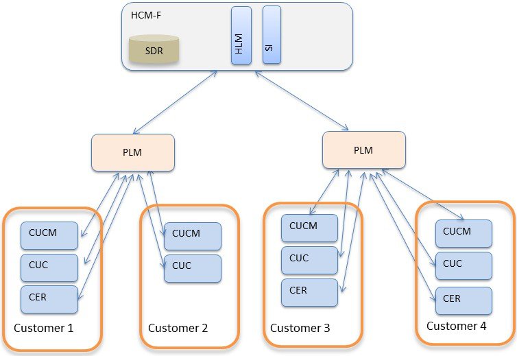
PLM is not supported for UC applications cluster versions higher than 11.x. Register all the 12.x UC applications cluster to CSSM.

HCM-F currently supports registration of UC Applications to Prime License Manager (PLM) for consuming the traditional PAK-based licenses. UC application versions 11.x or earlier supports registration through PLM. For more information about PLM, see Cisco Hosted Collaboration Solution License Management.

Smart Licensing helps simplify three core functions:

  • Purchasing: The software that you have installed in your network can automatically self-register themselves, without Product Activation Keys (PAKs).

  • Management: You can automatically track activations against your license entitlements. Also, you do not need to install the license file on every node. You can create License Pools (logical grouping of licenses) to reflect your organization structure. Smart Licensing offers you Cisco Smart Software Manager, a centralized portal that enables you to manage all your Cisco software licenses from one centralized website.

  • Reporting: Through the portal, Smart Licensing offers an integrated view of the licenses you purchased and the licenses that are deployed in your network. You can use this data to make better purchase decisions, based on your consumption.

Cisco Smart Software Licensing helps you to procure, deploy, and manage licenses easily, where devices register and report license consumption, removing the need for product activation keys (PAK). It Pools license entitlements in a single account and allow you to move licenses freely through the network, wherever you need them. It is enabled across Cisco products and managed by a direct cloud-based or mediated deployment model.

The Cisco Smart Software Licensing service registers the product instance, reports license usage, and obtains the necessary authorization from Cisco Smart Software Manager.

HCM-F enables the user to perform multiple tasks, such as, change the license deployment to Hosted Collaboration Solution (HCS), setting the transport mode to UC Applications, create token in CSSM, register the UC applications and validate the same, and so on. If there is a failure while performing the tasks, HCM-F collects the error messages from the UC application or CSSM, and updates the HCM-F Job entry with the issue details.

CSSM reports at smart account-level and product level. However, user information is not available at these levels. HCM-F provides the Service Inventory report and the HLM report of license usage at customer-level and virtual account level. It also provides Licensing dashboards to display the usage.

You can use Smart Licensing to:

  • See the license usage and count.

  • See the status of each license type.

  • See the product licenses registered on Cisco Smart Software Manager.

  • Renew License Authorization with Cisco Smart Software Manager.

  • Renew the License Registration.

  • Deregister with Cisco Smart Software Manager .

The deployment option for Smart Licensing:

Cisco Smart Software Manager
The Cisco Smart Software Manager (CSSM) is a cloud-based service that handles system licensing. HCM-F can connect to CSSM either directly or through a proxy server. HCM-F and UC applications use the selected Transport Mode. We recommend using a proxy server to connect to CSSM instead of connecting directly. Cisco Smart Software Manager allows you to:
  • Manage and track licenses.

  • Move licenses across virtual account.

  • Remove registered product instance.

To track smart account-related alerts, change the preference settings, and configure email notification. Navigate to Smart Software Licensing in Cisco Smart Software Manager.

For additional information, go to https://software.cisco.com.

Smart Versus Traditional Licensing

Traditional (node locked) licensing

Smart (dynamic) licensing

You procure the license and manually install it on the PLM.

Your device requests the licenses that it needs from CSSM.

Node-locked licenses - license is associated with a specific device.

Pooled licenses - Smart accounts are the company account specific that can be used with any compatible device in your company.

No common install base location to view the licenses that are purchased or software usage trends.

Licenses are stored securely on Cisco servers that are accessible 24x7x365.

No easy means to transfer licenses from one device to another.

Licenses can be moved between product instances without a license transfer, which greatly simplifies the reassignment of a software license as part of the Return Material Authorization (RMA) process.

Limited visibility into all software licenses being used in the network. Licenses are tracked only on per node basis.

Complete view of all Smart Software Licenses used in the network using a consolidated usage report of software licenses and devices in one easy-to-use portal.

Cisco Smart Software Manager (CSSM)

Cisco Smart Software Manager allows product instances to register and report license consumption.

You can use Cisco Smart Software Manager to:

  • Manage and track licenses

  • Move licenses across virtual account

  • Remove registered product instance


Note

Enable Javascript 1.5 or a later version in your browser.

We recommend using connected mode for the satellite connection.


For details on Cisco Smart Software Manager (CSSM), see https://software.cisco.com/.

Smart Accounts and Virtual Accounts
Smart Account
Cisco Smart Account is an account where all products that are enabled for Smart Licensing are deposited. Cisco Smart Account allows you to manage and activate your licenses to devices, monitor license use, and track Cisco license purchases.
Virtual Account
Smart Licencing allows you to create multiple license Pools or virtual accounts within the Smart Software Manager portal. Using the Virtual Accounts option, you can aggregate licenses into discrete bundles that are associated with a cost center so that one section of an organization cannot use the licenses of another section of the organization. For example, if you segregate your company into different geographic regions, you can create a virtual account for each region to hold the licenses and product instances for that region.

For details on Cisco Smart Accounts and Virtual Accounts, see https://software.cisco.com/.

Smart Licensing Deployment Options

The following options are available for connecting to CSSM:

Proxy (Cloud access through an HTTPs proxy)
In a proxy deployment method, Cisco products send usage information through a proxy server.

Note

Proxy is the recommended transport mode.


Direct (Direct Cloud Access)
In a direct cloud-access deployment method, Cisco products send usage information directly.

HCS 12.5 release does not support Smart Licensing APIs.

License Modes in Hosted Collaboration Mediation- Fulfillment

Currently, HCM-F supports the license modes of HCS, HCS-LE, and Enterprise. In a single HCM-F, one PLM can be in an HCS mode, another can be in an HCS-LE mode, and the third one can be in the Enterprise mode. The licensing mode is assigned to the PLM in version 11.x or earlier when it is created in the HCM-F. During the UC cluster assignment process to the PLM, the mode of the UC application is automatically changed to reflect the licensing mode of the PLM.

From HCS 12.5 release, Smart account or virtual account in CSSM does not have a concept of license mode. The license mode is only within HCM-F and UC applications. In HCM-F you need to set the license mode to a virtual account so that during assignment phase the UC Application could be assigned the same mode.

Once the virtual accounts are synced from CSSM to HCM-F, set the license mode before cluster assignment.

Default and Override at Each Level

At system level, 'Default license mode' is set in HCM-F. You can also set the license mode at each individual SA (Smart Account) level. By default SA level license mode is set at system level default value. It's simple and automatically takes care of entire license mode assignment.

  1. When the VAs (Virtual Accounts) are synced from CSSM to HCM-F, VAs get assigned to the license mode of the SAs.

  2. For each VA, the admin can change the license mode before assigning a cluster to VA.

  3. Once the cluster is assigned to a VA, the licensing mode of the VA can't be changed. You can change the licensing mode of the VA only after the clusters are unassigned from the VA.

Advantage: Its simple and automatically takes care of entire license mode assignment.

Disadvantage: There's a risk of how it's interpreted. For example, if admin updates SA level licensing mode, the license mode doesn't change for the virtual accounts. However, any new virtual account synced is assigned to this license mode. Also, the license mode settings at SA level may show one type whereas the license mode settings at individual Virtual Accounts level may show a different type.

Set License Mode at VA level before Cluster Assignment
  • Default license mode always exists and is used only for PLM-based assignments.

  • No license mode is present at SA (Smart Account) level.

  • The license mode exists at the VA level. However, it has the value 'None' when the VA is synced from CSSM.

Cloud Connectivity

Set the transport mode in HCM-F to connect HCM-F and UC applications to CSSM.

The first option is Proxy transport mode (Connection to Cisco Smart Software Manager through proxy server) where data transfer happens directly over the Internet to the Cloud server through an HTTPs proxy.

The third option is Direct transport mode (Direct connection to Cisco Smart Software Manager on cisco.com) where data transfer happens over the Internet to the CSSM (Cloud server) directly from the devices to the cloud through HTTPs. In Direct transport mode, HCM-F connects directly to the Cisco Smart Software Manager on cisco.com.

When Smart Account is provisioned with client credentials (Client ID and Client Secret) in HCM-F, the HCM-F authenticates with the Cisco Authentication Gateway with client credentials. HCM-F gets the access token from Cisco Authentication Gateway for communicating with CSSM.

Supported Licensing Model

The supported license types for HCM-F Smart Licensing are:

  • HCS UCM Essential

  • HCS UCM Basic

  • HCS UCM Foundation

  • HCS UCM Standard

  • HCS UCM TelePresence Room

  • HCS Emergency Responder

  • HCS Unity Connection Basic

  • HCS Unity Connection Enhanced

  • HCS Unity Connection Speech Connect

  • HCS Unity Connection Standard

Smart Accounts provide full visibility into all types of Cisco software licenses except for Right-To-Use (RTU) licenses. The greatest benefit of a Smart Account is achieved when consuming a Smart License.

  • For Smart Licensing, no PAKs are required and it’s easy to order and activate Smart Licenses.

  • For Classic, PAK-based licenses, you gain enterprise-wide visibility of PAK licenses and devices that are assigned to the Smart Account.

  • For Cisco Enterprise Agreements (EA), you benefit from simplified EA management, enterprise-wide visibility, and automatic license fulfillment.

Smart Accounts are the gateway to three different portals:

  • For Smart Licenses, there is the Cisco Smart Software Manager, where Smart Licenses are stored and managed.

  • For Classic Licenses, there is the License Registration Portal, where Classic Licenses are deposited and managed.

  • For EAs, the EA Workspace is a tool where users can manage their Enterprise Agreement licensing activities all in one place.

When the user orders the licenses in CCW or Cisco commerce, user should select the smart account and virtual account, so that all the licenses are sent to the virtual account.

Cisco Prime Collaboration Assurance Overview

Cisco Prime Collaboration Assurance and Analytics provides real-time monitoring, proactive troubleshooting, and long term trending and analytics in one integrated product.

Cisco Prime Collaboration Assurance provides integrated service assurance management through a single, consolidated view of the Cisco voice, and video collaboration environment. It includes continuous, real-time monitoring and advanced troubleshooting tools for Cisco Unified Communications and Cisco TelePresence systems including the underlying transport infrastructures.

For more information about Cisco Prime Collaboration Assurance and Analytics, see the Cisco Prime Collaboration Assurance documentation: https://www.cisco.com/c/en/us/support/cloud-systems-management/prime-collaboration-assurance-12-1/model.html

Voice and Video Unified Dashboard

The Cisco Prime Collaboration Assurance dashboards enable end-to-end monitoring of your voice and video collaboration network. A summary of the information displayed is as follows:

Dashboard Description Cisco Prime Collaboration Assurance Options
Service Experience Information about sessions and alarms. Quality of service. Cisco Prime Collaboration Assurance Advanced
Alarm Information about management devices. Alarm summaries. Cisco Prime Collaboration Assurance
Performance Provides details on critical performance metrics of each managed element. Cisco Prime Collaboration Assurance Advanced
Contact Center Topology Information about Contact Center components such as CUIC, CVP and Unified CCE. Unified Contact Center Topology View . Cisco Prime Collaboration Contact Center Assurance
Utilization Monitor Information about endpoints and their utilization, conferencing devices, and license usage. Cisco Prime Collaboration Assurance Advanced

Refer to the Prime Collaboration Dashboards to see how the dashlets are populated after deploying the Cisco Prime Collaboration Assurance servers.

Device Inventory/Inventory Management

You can discover and manage all endpoints that are registered to Cisco Unified Communications Manager (phones and TelePresence), Cisco Expressway (TelePresence), CTS-Manager (TelePresence) and Cisco TMS (TelePresence). In addition to managing the endpoints, you call also manage multipoint switches, application managers, call processors, routers, and switches that are part of your voice and video collaboration network.

As part of the discovery, the device interface and peripheral details are also retrieved and stored in the Cisco Prime Collaboration Assurance database.

After the discovery is complete, you can perform the following device management tasks:

  • Group devices into user defined groups.

  • Edit visibility settings for managed devices.

  • Customize event settings for devices.

  • Rediscover devices.

  • Update inventory for managed devices.

  • Suspend and resume the management of a managed device.

  • Add or remove devices from a group.

  • Manage device credentials.

  • Export device details.

Voice and Video Endpoint Monitoring

Service operators need to quickly isolate the source of any service degradation in the network for all voice and video sessions in an enterprise.

For Prime Collaboration Assurance 11.1 and earlier

Cisco Prime Collaboration Assurance provides a detailed analysis of the end-to-end media path, including specifics about endpoints, service infrastructure, and network-related issues.

For video endpoints, Cisco Prime Collaboration Assurance enables you to monitor all point-to-point, multisite, and multipoint video collaboration sessions. These sessions can be ad hoc, static, or scheduled with one of the following statuses:

  • In-progress

  • Scheduled

  • Completed

  • No Show

Cisco Prime Collaboration Assurance periodically imports information from:

  • The management applications (Cisco TMS) and conferencing devices (CTMS, Cisco TS) on the scheduled sessions.

  • The call and conferences control devices (Cisco Unified CM and Cisco Expressway) shown on the registration and call status of the endpoints.

In addition, Cisco Prime Collaboration Assurance continuously monitors active calls supported by the Cisco Unified Communications system and provides near real-time notification when the voice quality of a call fails to meet a user-defined quality threshold. Cisco Prime Collaboration Assurance also allows you to perform call classification based on a local dial plan.

See Prerequisites for Setting Up the Network for Monitoring in Cisco Prime Collaboration Network Monitoring, Reporting, and Diagnostics Guide, 9.x and later to understand how to monitor IP Phones and TelePresence.

Diagnostics

Prime Collaboration uses Cisco Medianet technology to identify and isolate video issues. It provides media path computation, statistics collection, and synthetic traffic generation.

When network devices are medianet-enabled, Prime Collaboration provides:

  • Flow-related information along the video path using Mediatrace

  • Snapshot views of all traffic at network hot spots using Performance Monitor

  • The ability to initiate synthetic video traffic from network devices using the IP Service Level Agreement (IP SLA) and Video Service Level Agreement Agent (VSAA) to assess video performance on a network.

In addition, for IP phones, Prime Collaboration uses the IP SLA to monitor the reachability of key phones in the network. A phone status test consists of:

  • A list of IP phones to test.

  • A configurable test schedule.

  • IP SLA-based pings from an IP SLA-capable device (for example, a switch, a router, or a voice router) to the IP phones. Optionally, it also pings from the Prime Collaboration server to IP phones.

For Cisco Prime Collaboration Release 11.5 and later

Cisco Medianet Technology is not supported.

Fault Management

Prime Collaboration ensures near real-time quick and accurate fault detection. After identifying an event, Prime Collaboration groups it with related events and performs fault analysis to determine the root cause of the fault.

Prime Collaboration allows to monitor the events that are of importance to you. You can customize the event severity and enable to receive notifications from Prime Collaboration, based on the severity.

Prime Collaboration generate traps for alarms and events and sends notifications to the trap receiver. These traps are based on events and alarms that are generated by the Prime Collaboration server. The traps are converted into SNMPv2c notifications and are formatted according to the CISCO-EPM-NOTIFICATION-MIB.

Reports

Prime Collaboration Assurance provides the following predefined reports and customizable reports:

  • Inventory Reports—Provide IP phone, audio phone, video phone, SRST phone, audio SIP phone, and IP communicator inventory details. Inventory reports also provide information about CTI applications, ATA devices, and the Cisco 1040 Sensor. Provides information on managed or unmanaged devices, and the endpoints displayed in the Endpoints Diagnostics page.

  • Call Quality Event History Reports—Provide the history of call quality events. Event History reports can display information for both devices and clusters. You can use Event History to generate customized reports of specific events, specific dates, and specific device groups.

  • CDR & CMR Reports — Provides call details such as call category type, call class, call duration, termination type, call release code, and so on.

  • NAM & Sensor Reports— Provides call details collected form Sensor or NAM such as MOS, jitter, time stamp, and so on.

  • TelePresence Endpoint Reports — Provides details on completed and in-progress conference, endpoint utilization, and No Show endpoints. TelePresence reports also provide a list of conferencing devices and their average and peak utilization in your network.

  • Activity Reports—Provide information about IP phones and video phones that have undergone a status change during the previous 1 to 30 days.

Cisco Expressway

Cisco Expressway can be deployed in Cisco Hosted Collaboration Solution for Collaboration Edge to support Over the Top (OTT) connectivity for HCS Endpoints and for Business to Business calls using a shared Expressway.

Shared Expressway Business to Business (B2B)

For Business to Business calls using a shared Expressway: Cisco HCS provides the option to deploy the expressway as a shared component across tenants to enable Business to Business calls to/from any non-HCS businesses thru Internet. This enables sharing of the rich media licenses across multiple enterprises. Cisco Expressway provides secure signaling and media paths through the firewalls into the enterprise for the key protocols identified. Traversal links established from the control platform toward each extend will be used to carry multiplexed traffic through the firewall. Each protocol is to be secured at the edge with TLS and username/password will also be used as an authentication mechanism for soft clients.

Shared Expressway OTT

For Collaboration Edge to support Over the Top (OTT) connectivity for HCS Endpoints: Cisco Collaboration Edge architecture supports the Cisco Expressway Series components Cisco Expressway-Connect and Cisco Expressway-Extend in the TelePresence and Collaboration Edge video solutions.

For OTT deployments: to optimize DCI media traffic, Cisco Expressway-Connect is deployed in the outside VLAN's subnet and Cisco Expressway-Extend is isolated in a DMZ. The highlights of this design are:
  • Cisco Expressway-Extend does not share the VLAN on the inside with endpoints outside of the VLAN.

  • Cisco Expressway-Connect is treated as an internal endpoint.

  • Inter DC media when endpoints dial into Voice mail or MOH server in the other Data Center (in CoWan deployments) is not routed through DCI, but through the MPLS network.

Connectivity to Unified Communications Manager (for OTT) can be either secure or non-secure from remote endpoints. Two distinct sessions, such as TCP and TLS, will be established with session traffic multiplexed over these connections.

Audio and Video media streams are to be secured with SRTP and BFCP, IX and FECC are also negotiated and relayed through the edge components.


Note

For OTT deployments, hard endpoints must have client certificates to connect to the edge and therefore, must be configured in secure mode.

To install or upgrade Collaboration Edge components Cisco Expressway-Extend and Cisco Expressway-Connect, see http://www.cisco.com/c/en/us/support/unified-communications/expressway-series/tsd-products-support-series-home.html.


Note

The content under the title OTT Deployment and Secured Internet with Collaboration Edge Expressway is existing content in the current SRND that has been added for context.


Aggregation System Architecture

Aggregation Layer

Session Border Controller (SBC) in HCS

The SBC acts as a media and signaling anchoring device. It’s also used as a Cisco HCS demarcation in the aggregation layer. In this capacity, the SBC normalizes communication between HCS and the outside world through a different IP network or the IP Multimedia Subsystem (IMS) cloud.