Network Architecture

Service Provider IP Infrastructure

This section covers the configuration of the service provider (SP) MPLS/IP Core used to transport traffic from the customer sites to the Data Center hosting HCS. The PE devices establish L3VPNs for each customer to ensure traffic isolation while the P devices provide efficient transport across the SP backbone.

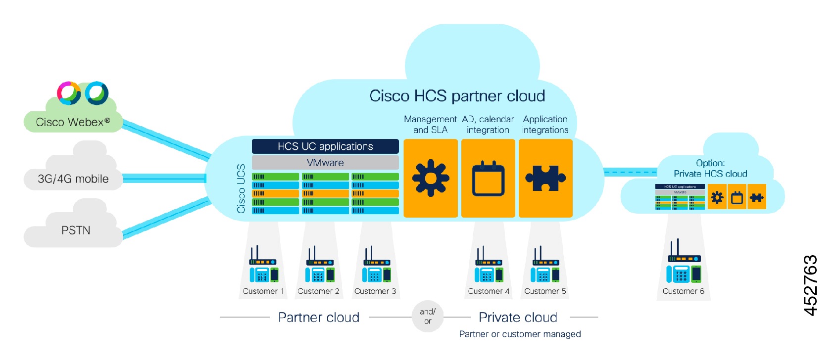
You can implement NAT services for Service Assurance, management or security. Hosted Collaboration Solution (HCS) defines an environment where customer-specific applications are hosted in the service provider Data Centers (DCs) rather than on premises. Inevitably, this also means that applications for multiple customers are hosted in the same SP DC. Customer Premises Equipment (CPE), IP endpoints within the customer premises require connectivity to the service provider data center, which is provided through a robust SP IP infrastructure.

This section takes a look at basic IP connectivity requirements and outlines the HCS IP deployment model and functions of devices at each layer within the SP IP infrastructure. This section also outlines various design considerations for IP based services such as Dynamic Host Configuration Protocol (DHCP), network address translation (NAT), Domain Name System (DNS, and Network Time Protocol (NTP), and provides more details on connectivity requirements, maximum transmission unit (MTU) size, and addressing recommendations.

Service Provider IP Connectivity Requirements

To understand overall service provider IP Infrastructure connectivity, you must understand the following:

  • What devices require IP connectivity for an end-to-end service

  • What traffic traverses service provider and Enterprise customer networks

The following table outlines the set of components and their intended placement within the end-to-end system architecture.

Table 1. Components Requiring IP Connectivity Device Category Network Placement - Sample Device
Device category Network placement Sample device
IP Endpoints Customer Premises IP phones (voice and video), Presence/IM Clients (Cisco Unified Personal Communicator)
SP Managed components Customer Premises SRST CPE, Media Resources CPE, Media Resources Managed CPE
Per-Customer Servers SP Data Center Cisco Unified Communications Manager, Cisco Unity Connection, Cisco Unified Communications IM and Presence Service
Shared Management Components SP Data Center

Cisco Prime Collaboration Assurance (PCA) for HCS

Multitenant signaling aggregation SP VoIP aggregation within IP Infrastructure Third- party SBC

Each of the devices shown in the preceding table requires IP connectivity to one or more other devices.

HCS Traffic Types

There are typically multiple traffic flows for different components within the service provider infrastructure, each with a distinct purpose and requirement. These traffic flows are documented as follows.

Traffic Type and Requirements

Signaling
  • For each customer, on-premises endpoints must have reachability to its per-customer services components in the service provider's data center.

  • Each per-customer instance of Unified Communications Manager in the service provider data center must have reachability to a multitenant signaling aggregation component in the service provider's data center or VoIP network.

  • On-premises components of one customer must not have reachability to the per-customer services components of another customer.

Media
  • On-premises endpoints of one customer must have reachability to on-premises endpoints of another customer for interenterprise on-net calls.

  • On-premises endpoints must have reachability to PSTN media gateway.

  • (MGW) in the service provider's data center.

Management
  • Per-customer management components in the service provider's data center must have reachability to multitenant management components in the service provider's data center.

  • In the case of managed CPE or SRST routers, the on-premises CPE management address must have reachability to per-customer management components in the service provider's data center.

  • On-premises LDAP server to the customer IM and Presence Service server instance in the service provider's data center.

Data
  • Connectivity between multiple sites within an enterprise customer.

  • No direct connectivity between sites of different enterprise customers.

  • Because multiple enterprise customers share service provider IP (and data center) infrastructure as a transport medium, some fundamental design and security constraints must be addressed:

    • On-premises components of one enterprise must not negatively impact hosted components of other enterprises or the service provider network in general.

    • Customer traffic must be segregated as it passes through the service provider IP (and data center) infrastructure. This is because multiple customers use the same infrastructure to access applications hosted in the service provider data center.

    • While providing over traffic segregation, the service provider must support some intercustomer communication. For example, media for intercustomer on-net calls can be sent over an IP network between endpoints in two different enterprises without being sent to the PSTN.

    • IP network design must consider potential overlapping address spaces of both on-premises and hosted components for multiple enterprises.

HCS Management IP Addressing Scheme

You must deploy the following Cisco HCS and HCS-related management components within a global address space:

  • Hosted Collaboration Mediation Fulfillment Layer (HCM-F)

    Note

    The use of network address translation (NAT) address space is not recommended for management applications such as Cisco Hosted Collaboration Mediation Fulfillment Layer (HCM-F) when they are accessed from customer Unified Communications applications.


  • Cisco Prime Collaboration Assurance

  • Unified Communications Manager

  • vCenter

  • Prime License Manager

These components must be directly accessed from the individual customer domains without network address translation of the management components.

Figure 1. HCS Management Addressing Scheme

The deployment scheme shown in the preceding figure is the preferred and validated method, which enables all management features to work correctly.


Note

Some deployments do not follow the above recommended best practice, and problems with some features have been encountered; for example, platform upgrade manager or automation of assurance provisioning. We highly recommend that you migrate noncomplying deployments to the above Cisco HCS supported and validated deployment deployment (in other words, addresses of management applications such as HCM-F) must be directly accessible (without NAT) from the UC applications, whereas the UC applications can have their addresses translated (NAT) while being accessed from management applications.


Service Provider NAT/PAT Design

With the use of per-customer MPLS VPN, Cisco HCS end customers can end up using overlapping IP addresses. Another possibility is that a service provider will use a fixed, overlapping subnet with possibly the same IP addresses for all customers to simplify operation complexities.

While MPLS provides the ability to use overlapping subnets across multiple customers, it also causes problems for out-of-band management of overlapping customer subnets. HCS recommended design uses NAT between management systems and customer UC applications. which use overlapping addresses.

Grouping VLANs and VLAN Numbering

Cisco recommends that when you design Layer 2 for a Cisco HCS deployment, you group the VLANs based on their usage. The current Service Provider Cisco HCS data center design assumes that each end customer consumes only two VLANs; however, it is possible to configure four VLANs for each end customer.

Use the following VLAN numbering scheme if four VLANs are configured for each end customer:

  • 0100 to 0999: UC Apps (100 to 999 are the customer IDs)

  • 1100 to 1999: outside VLANs (100 to 999 are the customer IDs)

  • 2100 to 2999: hcs-mgmt ( 100 to 999 are the customer IDs)

  • 3100 to 3999: Services ( 100 to 999 are the customer IDs)

  • Use all the unused VLANs x000 to x099 (where x is 1, 2, or 3) and VLANS 4000 to 4095 for other purposes

Use the following number scheme if only two VLANs are configured for each end customer:

  • 0100 to 1999: UC Apps (100 to 999 are the customer IDs for Group 1)

  • 2100 to 3999: outside VLANs (100 to 999 are the customer IDs for Group 1)

Use the following numbering scheme for additional end customers:

  • 2100 to 2999: UC Apps (100 to 999 are the customer IDs for Group 2)

  • 3100 to 3999: outside (100 to 999 are the customer IDs for Group 2)

  • Use the unused VLANs for other purposes

While this is the recommended grouping of VLANS to help you scale the number of customers that can be hosted on a Cisco HCS platform, you may reach the upper limit of customers due to limitations in other areas of the Cisco HCS solution.

VPN Options

The following VPN options are supported in an HCS deployment:
  1. MPLS VPN
  2. Site-to-Site IPsec VPN
  3. FlexVPN
  4. AnyConnect VPN
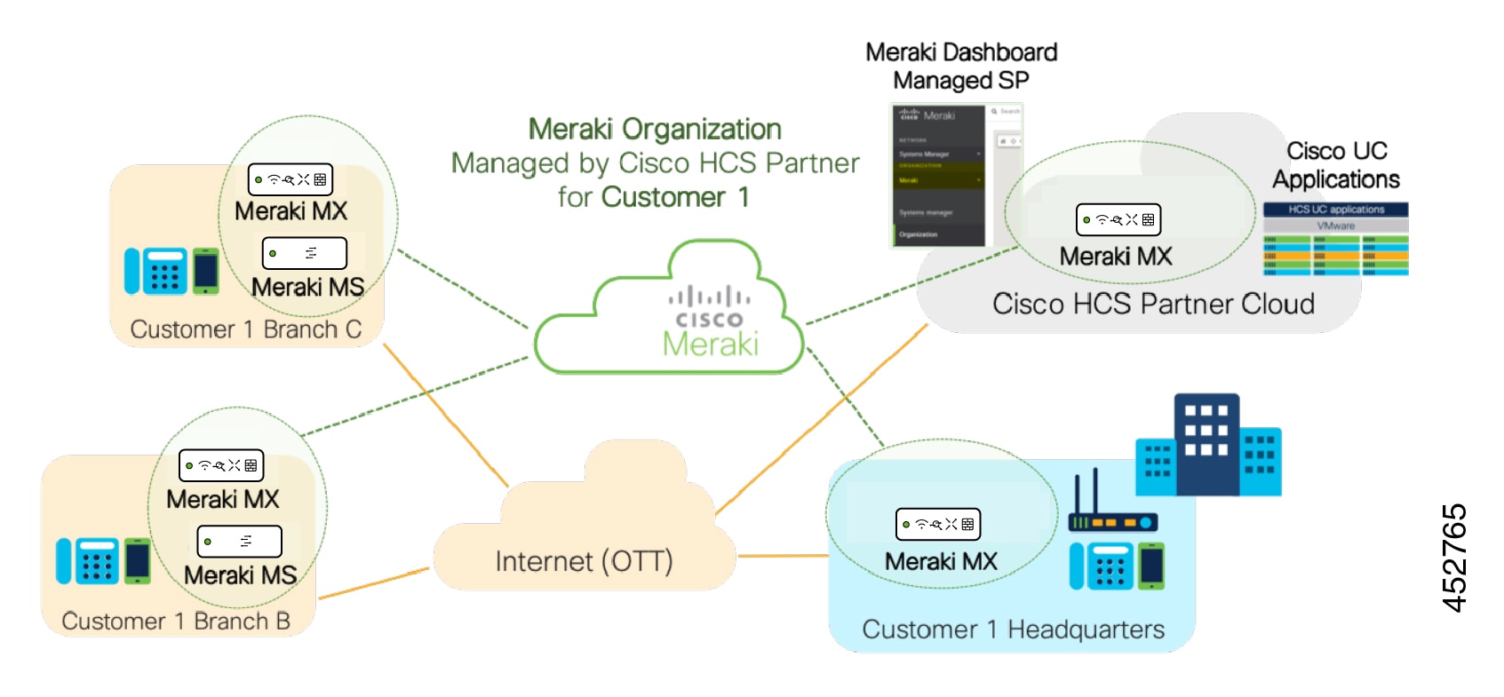
  5. For access options that do not require VPN, see Cisco Expressway Over-the-Top Solution Overview

Service Provider IP infrastructure design MPLS VPN

Cisco HCS recommended IP infrastructure design looks to satisfy all the connectivity requirements for both services and management, as outlined in an earlier section, securely with complete segregation between customers in multitenant service provider data centers.

Cisco HCS reference IP infrastructure design revolves around the following two key principles:

  • Use of MPLS VPN and VLAN to provide customer traffic isolation and segregation

Figure 2. High-level Service Provider IP Design

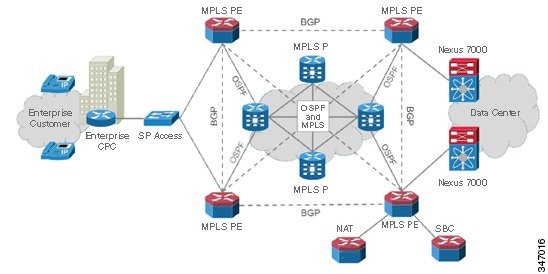
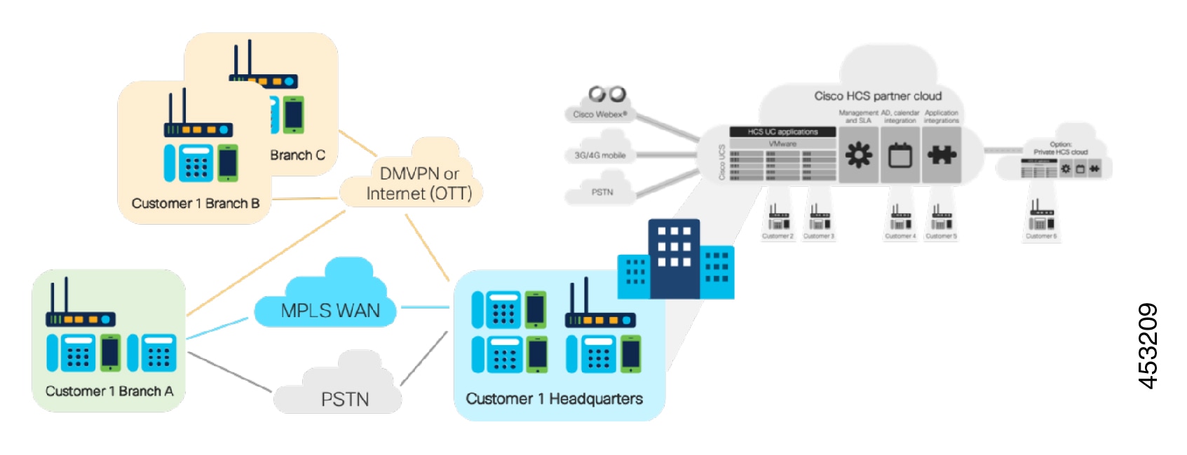
Endpoints in individual customer sites connect to the service provider network through MPLS Provider Edge (PE) devices. Customer traffic may be untagged, in which case physical interfaces are used on MPLS PE devices. Or the service provider may choose to use a bump-in-the-wire and may aggregate multiple customers on the same physical MPLS PE interface, in which case each customer is assigned its own VLAN and each customer is terminated on a customer-specific sub-interface with 802.1Q encapsulation that matches the VLAN sent by customer.

The customer-facing MPLS PE device is responsible for implementing per-customer MPLS Layer 3 Virtual Private Network (VPN), which provides customer traffic separation through the service provider MPLS-IP infrastructure.

As an MPLS VPN PE node this device is responsible for the following:

  • Defining customer-specific VRF

  • Assigning customer-facing interfaces to VRF

  • Implementing PE-CE Routing protocol for route exchange

  • Implementing Multiprotocol BGP (M-BGP) for VPN route exchange through the MPLS Core

  • Routing redistribution between PE-CE and M-BGP routing protocol

MPLS Provider (P) routers are core service provider routers, responsible for high-speed data transfer through the service provider backbone. Depending upon overall service provider design, this P router may or may not be part of M-BGP deployment. Other than regular service provider routing and MPLS operations, there is no specific Cisco HCS-related requirement.

Per-customer MPLS VPN services initiated at the customer-facing MPLS PE devices are terminated at the data center facing MPLS PEs. The implementation at data center core facing MPLS PEs is the same as the customer-facing PE device. This effectively means that MPLS L3 VPN is used only in the service provider MPLS/IP core for customer data transport.


Note

Use of labels for MPLS VPN may push the packet size beyond the default maximum of 1500 bytes that may cause fragmentation in some cases. A good practice is to increase MTU size to accommodate these added bytes.


The data center core-facing interfaces on the MPLS PE implement a per-customer sub-interface, which is configured for the customer VRF and is a VLAN unique to each customer. In other words, customer traffic handoff from service provider core to the data center core devices is based on per-customer VLAN. Data center infrastructure uses this VLAN to implement VRF-Lite for customer traffic separation.

A similar approach is used to hand over customer traffic to the Session Border Controller (SBC). Any intercustomer calls, or any calls to PSTN are done through SBC. The Nexus 7000 device hands off customer traffic to SBC using a per-customer sub-interface, similar to data center handoff. The Session Border Controller is responsible to correctly route customer calls, based on the configuration within SBC.

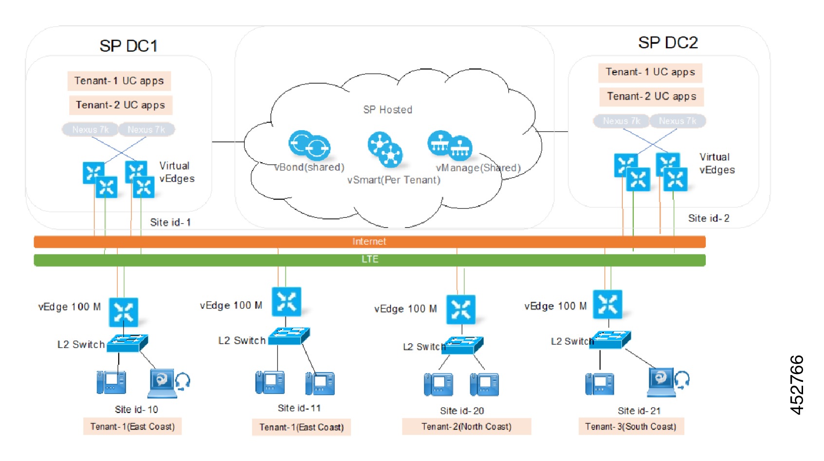
HCS Tenant Connectivity Over Internet Model

Cisco HCS using IPSec aware VPN technology allows you to enable an alternative option in the HCS P(roductized) V(alidated) S(olution) to offer SMBs without MPLS VPN connectivity a secure low cost alternative to connect to the service provider's data center in the cloud using the internet. This setup does not require any VRF configuration on the customer premise side, which eliminates the need of costly MPLS VPN.


Note

This solution is meant to enable a Cisco HCS tenant site and not a single user.

IPsec is a framework of open standards. It provides security for the transmission of sensitive information over unprotected networks such as the Internet. IPsec acts at the network layer, protecting and authenticating IP packets between participating IPsec devices or peers, such as Cisco routers.

Figure 3. Architecture for Site Connectivity Over Internet

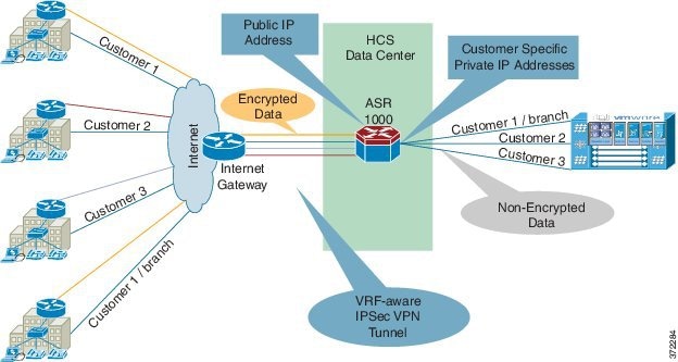
In the above diagram of the IP gateway, the device service provider typically has in their IP cloud for the Internet connectivity. There is no mandate on which IP router one may use, as long as it provides the IP routing capabilities for the incoming traffic over IPSec to the appropriate VPN concentrator in the service provider's HCS data center for IPSec VPN tunnel termination. As shown in the diagram, the VPN concentrator recommended for this kind of deployment is ASR 1000, which sits inside the Service Provider Cisco HCS Data Center as a centralized VPN concentrator. This is called Site-Site IPSec VPN tunnel on ASR router.

Figure 4. Detailed Architecture for Connectivity Over Internet

As shown above, the cloud for the MPLS traffic and cloud for the Internet traffic are considered to be different from one another in terms of how they ingress to the service provider's network. For the traffic coming out of Internet, the IP gateway is the ingress point, where as in the case of the traffic coming from the MPLS cloud, the PE is the ingress point.

The above architecture applies to the aggregation-only layer in the above design within the data center.

Deploy the VPN concentrator as other services are typically deployed in this layer. Use the ASR 1000 dedicated as a VPN concentrator as encryption and decryption happen on the ASR 1000. Running other services may impact the performance overall.

There are multiple ways to deploy this solution within the Service Provider Cisco HCS Data Center using two different techniques.

  1. Use Layer 3 between the IP gateway and ASR 1000. In this case, the Nexus 7000 switch is used as a router.

    The Nexus 7000 acts as a default gateway for ingress and egress traffic for encrypted traffic in the global routing table.

  2. Use Layer 2 technology between the IP gateway and ASR 1000, and in this case the Nexus 7000 switch is transparent to the traffic and ASR 1000.

    ASR 1000 acts as a default gateway for ingress and the IP gateway is used as a egress default gateway for encrypted traffic in the global routing table.

You can deploy using the Layer 2 connectivity between the IP gateway and ASR 1000. This keeps this inter-connectivity architecture as an overlay network on top of the Cisco HCS VPN based network.

There are multiple ways to deploy this over the Internet solution within the SP's data center.

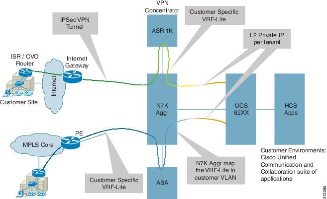
  1. Bring the IPsec tunnel directly to the ASR 1000 (VPN concentrator), which decrypts into VRF and connects to the south VRF on Nexus 7000 using a static route per tenant. On this tenant, it points to the Nexus 7000 aggregation and similarly builds a static route per tenant on Nexus 7000 for any outgoing traffic. You also require one more static route on the Nexus 7000 toward the SBC for any inter SMB traffic or PSTN traffic.
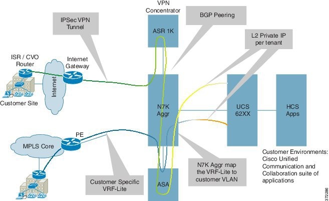
  2. 2. Bring the IPsec tunnel directly to the ASR 1000 K (VPN concentrator) and connect it to the Nexus 7000 aggregation using dynamic routing protocol BGP. Dynamic BGP also has the advantage to redistribute the IPSec RRI routes from ASR to Nexus 7000 automatically.

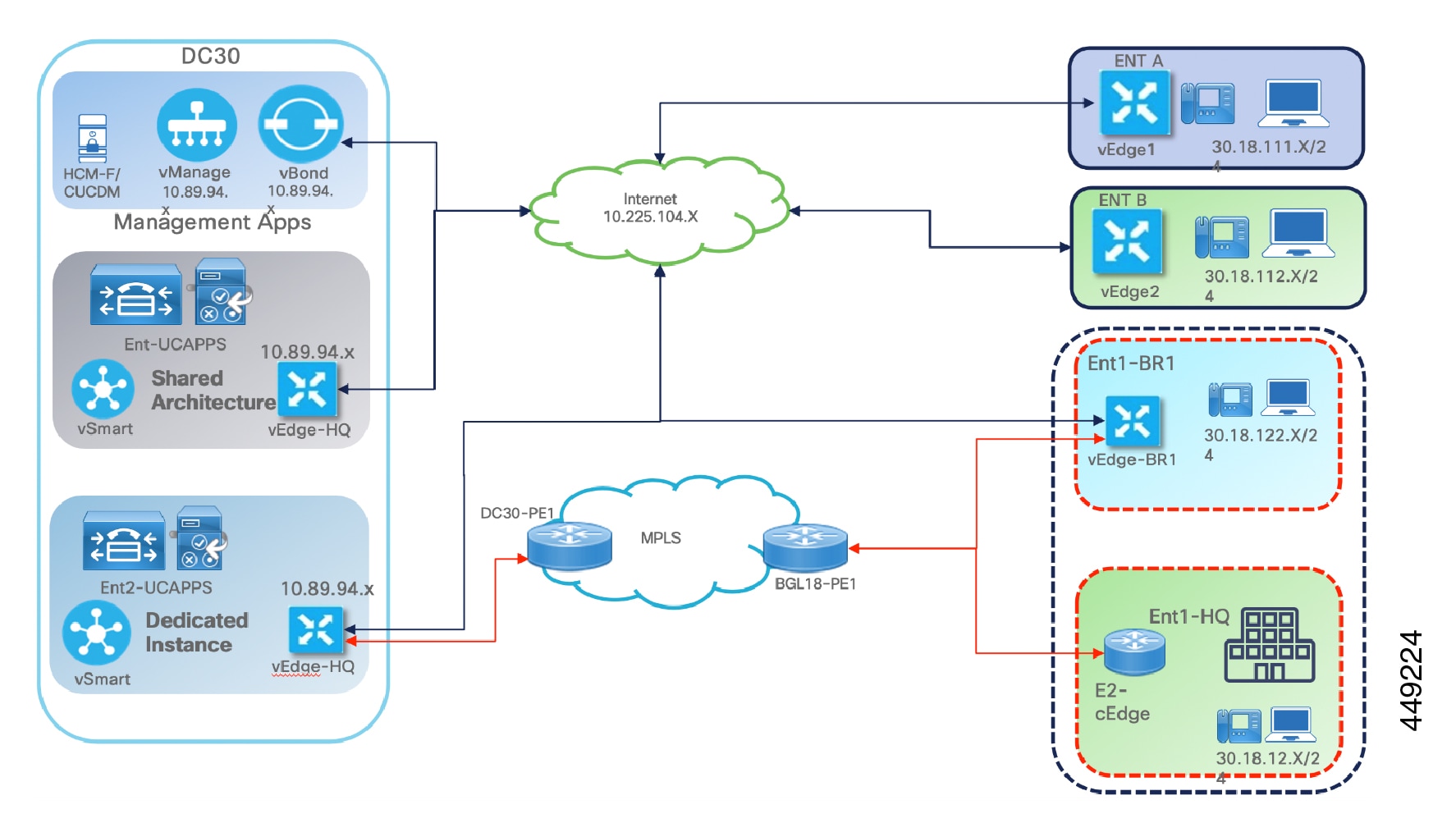
In the diagram below, the ASR 1000-VPN decrypts into VRF and this VRF is connected to the Northbound VRF on N7000. Then it goes to ASA Outside, and from ASA Inside to Southbound VRF on the Nexus 7000, then to UC Applications.

Figure 5. Detailed Architecture for Connectivity Over Internet

The IP address on the Customer Premise Equipment (CPE) and the VPN concentrator need to be in the public domain from the reachability perspective. For all the various different customer sites, there is only one common public IP address, which they use to connect.

IPSec tunnels are sets of security associations (SAs) that are established between two IPsec peers. The SAs define the protocols and the algorithms to be applied to sensitive packets and specify the keying material to be used by the two peers. SAs are unidirectional and are established per security protocol (AH or ESP)

With IPsec, you define the traffic that should be protected between two IPsec peers by configuring access lists and applying these access lists to interfaces by way of crypto map sets. Therefore, traffic may be selected on the basis of source and destination address, and optionally Layer 4 protocol, and port.

Note

The access lists used for IPsec are used only to determine the traffic that should be protected by IPsec, and not the traffic that should be blocked or permitted through the interface. Separate access lists define blocking and permitting at the interface.

Access lists associated with IPsec crypto map entries also represent the traffic that a device requires to be protected by IPsec. Inbound traffic is processed against the crypto map entries--if an unprotected packet matches a permit entry in a particular access list associated with an IPsec crypto map entry, that packet is dropped because it was not sent as an IPsec-protected packet.

Cisco recommends static IP addresses on the CPE device and on the VPN concentrator to avoid teardown of the IPSec tunnel. If the CPE device is using the DHCP or dynamic IP address scheme, there is no way to establish the tunnel from the central site to the remote site.

FlexVPN

FlexVPN is deployed in HCS as a site-to-site VPN, between the customer site and the hosted HCS datacenter. The FlexVPN based site-to-site VPN is easy to configure with IKEv2 smart defaults feature. The deployment model only requires a customer to have internet access and FlexVPN capable routers from HCS. Both dedicated or shared Cisco Unified Communications Manager can be used to offer HCS to customers behind the FlexVPN. The following key assumptions are made with regard to the FlexVPN support:

  • Endpoints deployed in the customer premise are directly accessible at layer 3 level from UC Applications deployed in the HCS data center.
  • No NAT is assumed between the customer endpoints and the UC applications.
  • The Customer VPN client router may be connected to the Internet domain from behind a NAT enabled internet facing router.
  • The VPN client router’s WAN facing address may be private and may be dynamically assigned.
  • The VPN server for the HCS may need to support the configuration, such that a common public IP can be used for all customer VPN client router connectivity.
  • Dual Tunnels can be established to two different FlexVPN server routers and tracking enabled at the client side to failover.
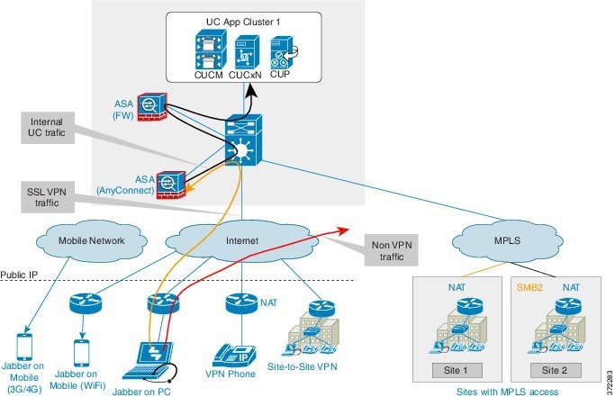
AnyConnect VPN

Cisco AnyConnect VPN Client provides secure SSL connections for remote users. You can secure connections through the Cisco ASA 5500 Series using SSL and DTLS protocols. It provides a broad desktop and mobile OS platform support.

ASA for AnyConnect is independent of the existing Firewall ASA in Cisco HCS. You need one ASA per cluster as multi-context SSL VPN support in ASA is not available yet. AnyConnect split tunneling allows only the configured applications to go through the VPN tunnel while other Internet traffic from that endpoint goes outside of the VPN.

Figure 6. AnyConnect

Signaling Aggregation Infrastructure

The Cisco HCS Aggregation layer provides a centralized interconnect to the SP cloud. Aggregation layer is a demarcation for Cisco HCS and a central point for all off-net calling capabilities to Unified Communications applications at the Unified Communications infrastructure layer. The aggregation layer enables common services to be delivered to multiple hosted businesses in a uniform manner. The services typically include:

  • SIP/PSTN trunking

  • Mobile, IMS

  • TelePresence

  • Contact Center Integration

  • Regulatory Services (Emergency Services)

  • Cisco Webex Cloud Connected Audio

Figure 7. Cisco HCS Aggregation Layer

Cisco HCS offers a number of deployment models, and depends on type of services, interconnect and aggregation component preferences. The different aggregation components can be deployed in various combinations to provide different services. In each case an “HCS demarcation” point exists which provides a logical and administrative separation between the service provider network and Cisco HCS solution for the purposes of network interconnect. The following figure shows the different deployment models and the demarcation in each case.

Figure 8. Deployment Models and Cisco HCS Demarcation

Cisco HCS offers a number of deployment models that can be used depending on customer services, interconnect and component preferences.

The different aggregation components can be deployed in various combinations to provide different services. In each case an “HCS demarcation” point exists which provides a logical and administration separation between the SP network and HCS solution for the purposes of network interconnect.

The third party SBC deployment models requires Service Providers to manage:
  • Validations and integration southbound (HCS) and north bound (SIP PSTN or IMS) integration

  • Feature and roadmap management

  • Support services

In addition, the aggregation layer provides the following functions depending on the device used, for example:

  • Multi VRF Support and Multi Customer Support

  • Media Anchoring

  • Protocol Conversions - Signaling Protocol, DTMF 2833 <> Notify, Late <> Early Offer

  • Security, Access, Control Network Demarcation, Admission Control and Topology Hiding

  • Routing—All Cisco HCS intercustomer calls traverse the aggregation layer and calls are switched by the service provider's switch.

The following table provides further details on the specific attributes of each deployment model.

Table 2. Aggregation Deployment Models
Deployment Model Attributes

Third-party SBC

In this deployment model the service provider has chosen to use an existing aggregation infrastructure or a third-party SBC.

Cisco HCS demarcation point in this case is SIP trunks from Cisco Unified Communications Manager clusters in the Application layer.

Per Customer SIP Trunking

With this deployment model, a Cisco HCS customer chooses to deploy a dedicated SIP trunk as opposed to using a centralized SBC. This may also be advantageous for Cisco HCS deployments where the Service Provider has not offered a centralized SBC.

IMS Network Integration

Some service providers have IMS in their network, which is the core network to provide routing and other common services billing, provisioning, and so on. In the Cisco HCS reference architecture, IMS network is placed at the Aggregation layer.

Originally, IMS was developed to provide core network functions for the mobile subscribers through the mobile access network and it evolved to provide these core network functions through other access networks as well.

Figure 9. Cisco HCS IMS Integration

Peer-based business trunking: The IMS and the NGCN networks connect as peers through Interconnect Border Control Functions (IBCF). The business subscribers are not necessarily provisioned in HSS. The point of interconnection between peer network and IMS is the IMS Ici interface. To enable Unified CM mobility features, provision Carrier Integrated Mobile in Cisco HCS Unified CM for IMS clients.

Application Server (AS): In this model Cisco HCS/Unified Communications Manager appears as the Application Server in the IMS network for the mobile phones, and the ISC (IMS Service Control) interface is used between IMS and Cisco HCS. The key requirement here is for Unified Communications Manager to support ISC interface route header for application sequencing so that Mobile Service Provider can mesh up features delivered by multiple application servers for the same call. Other significant requirements include the support of P-Charging-Vector and P-Charging-Function addresses.

Highlights of the Unified Communications Manager IMS Application Server feature are as follows:

  • A phone type "IMS-integrated Mobile (Basic)" is introduced. This is modeled after Cisco Mobile Client. Note that not all MI (Mobility Identity) attributed are available for IMS client.

  • SIP trunk type 'ISC'. The ISC trunk in Cisco Unified Communications Manager is added support to Route Header. Unified Communications Manager will use the top Route Header in the initial INVITE to decide how to handle this request, either as originating call or terminating call or as regular SIP call.

New call flows are based on a half call model for calls involving IMS-integrated clients. These are significantly different from the normal call flow in Cisco Unified Communications Manager. When the initial request (INVITE) is received on an SIP ISC trunk, the top most Route-Header must correspond to the Unified Communications Manager (the ISC trunk configuration shall have the ability to specify this URI to validate the route header) and there is at least one other Route-Header (corresponding to S-CSCF). If these conditions are not met, Unified Communications Manager fails the request with "403 Forbidden".

  • DTMF and other features for the IMS-integrated Mobile are similar to Cisco Mobile Client features (hold/exclusive hold/resume/conference/transfer/dusting).

  • P-Charging-Vector: The P-Charging-Vector header is defined by 3GPP to correlate charging records generated from different entities that are related to the same session. It contains the following parameters: ICID and IOI. Cisco Unified Communications Manager will use cluster ID, concatenated with a unique number as the icid_value. The IOI identifies both originating and terminating networks involved in a session/transaction.

Features and Services

All DTMF-based features offered to mobile clients in pre-10.0 Cisco HCS releases are applicable for IMS-integrated Clients in the Cisco HCS ISC interface model. However, signaling-based mid-call features are not supported over ISC interface.

IMS Application servers provide originating services and terminating services. The following Unified Communications Manager services are classified here:

Originating services: Call anchoring service to enable SNR features, Enterprise dial plan and class of service features, DTMF features. When mobile number is dialed, the call is forked to the mobile and shared desk phone and both ring. This is different from mobile client behavior in previous releases.

Terminating services: Call anchoring service to enable SNR features, DTMF features.

Unified Communications Manager can deliver the existing native Mobility feature through ISC interface to a mobile subscriber:

  • Enterprise dial plan (including extension dialing)

  • Enterprise policy (that is, class of service through Calling Search Space)

  • Single Number Reach through both enterprise DN

  • Single Number Reach even when someone dials the Mobile DN (that is, also rings the shared devices)

  • Call move between mobile and desk

  • Single VM and MWI

  • Mobile BLF presence status

  • DTMF-based mid-call features (hold/resume/transfer/conference/park/dust)

  • Some shared-link features including remote-in-use from desk and Barge from shared-disk

IMS-integrated Mobile feature support in Unified Communications Manager includes:

  • Mid-call Enterprise Feature Access Support Using DTMF-You can configure DTMF feature codes as service parameters: enterprise hold (default equals *81), enterprise exclusive hold (default equals *82), resume (default equals *83), transfer (default equal *84), conference (default equals *85) and dusting (default equals *74).

IMS Supplementary Services for VoLTE

The following IMS supplementary services (per GSMA IR.92 specification) are provided. These services are applicable for IMS clients provisioned in Unified Communications Manager:

  • ID Service—The existing Unified Communications Manager features Calling Number/Name, Presentation/Restriction, Privacy, and so on, are applicable for IMS client. There is no new functionality here.

  • Third-party Registration—This feature allows IMS network to send the Registration information to the Unified Communications Manager Application Server over the ISC interface when the IMS client registers with the IMS network. The Visited Network information in this Registration is saved by the Unified Communications Manager, which can be used to determine if the client is roaming or not.

  • Hold, Retrieve—This feature implements Hold/Resume in ISC interface as per the relevant specification.

  • Transfer—This existing Unified Communications Manager feature is applicable for an IMS client. There is no new functionality.

  • Conference—This is an ad hoc conference feature as defined in the relevant specification for IMS client.

  • Call Waiting—This is a Unified Communications Manager existing feature. There is no new functionality.

  • Call Forwarding—This is a Unified Communications Manager existing feature mapped to IMS flavors.

  • Call Barring—This is a new feature applicable for IMS clients. This allows blocking incoming calls to a client or outgoing calls from an IMS client. This has variations - roaming call, international call, and so on.

  • MWI (Message Waiting Indication)—The IMS client subscribes to MWI and receives notification.

HCS ACI-Integration

Solution Overview

Figure 10. HCS ACI Topology

In this diagram, we have three APIC Controller that is managing two ACI Leaf and two ACI Spine. APIC is connected to ACI Leaf with dual link from each APIC. Each ACI Leaf is connected to both ACI Spine.

There are port-channel(s) configured between ACI Leaf and Provider Edge router (ASR100X). On the logical routing L3Out(s) are used between PE and ACI Leaf, EBGP is used for routing traffic. ACI Spine acts as Route Reflector with AS 64000, while BGP on PE side is configured AS 65535.

Note: BGP AS number are for lab purpose (use as per your requirement).

From PE router we have two clouds, MPLS WAN cloud for connecting IP phones and soft clients (Jabber/Cisco Webex with UCM Calling) on Laptops in customer premise. Second cloud is internet breakout behind which we have MRA endpoints/Cisco Jabber/Cisco Webex with UCM calling running on Laptops connecting over Internet.

There are port-channel created between ACI Leaf and Fabric Interconnects which are managing Hyperflex nodes below. There is a VMM Integration done between ACI Leaf and VMware vCenter running on Standalone C-Series.

The Hyperflex HX cluster is hosting all the Virtual machine(s) include UC apps per customer, management apps, and virtual ASA.

This information area explains about DC1 and DC2 configuration that is described in this document.

In DC1, we have used “Optimized Application Centric approach”. Traffic Flow is using ACI Contracts (with Filters) between UC apps (inside/outside/customer-dmz) and also between Management Apps and UC Apps.

In DC1 each customer uses single VRF, Single L3Out but three EEPG:

  • 1st EEPG to vASA,

  • 2nd EEPG to reach Management Apps

  • 3rd EEPG to reach from DC1 to DC2

  • Similarly, we have used combination of L3Out to PE router

Service Graph is used for routing between UC Apps and customer premises.

Customer 1 Application(s) are done with Clustering Over WAN, example, DC1 has cucm pub, and DC2 has cucm.


Note

Both the Datacenters, DC1, and DC2 uses vASA.


Customer 2 Application(s) are all residing in DC2 only, which has integration Physical FTD in HA cluster.

In DC2, we have used “Network-centric approach”.

In DC2, customer has:

  • 1st VRF for inside apps like CUCM

  • 2nd VRF for outside apps like EXP-C

  • 3rd VRF for dmz leg of exp-e in customer

  • One common vrf for transit

We have used individual L3Out(s) in corresponds to each VRF created for reaching vASA inside, 2nd L3Out for vASA outside interface, and so on.

Note: This approach is recommended to partner(s) for deploying ACI with HCS as this mimic existing HCS network-centric design with ACI (such as, vlan = Bridge Domain = End Point Group).

There are two firewall options validated in lab – vASA and physical FTD with multi-instance. Other options not tested are vFTD and Physical ASA with multi context.

Following are the considerations:

  • UC Apps are inside VRF

  • EXP-C is residing in VRF-Outside

  • EXP-E has two NIC – NIC1 in customer dmz-vrf, NIC2 in dmz-in vrf

There is one vASA per customer firewall(s) being used. We also have one vASA for management-vASA, and dmz-vASA.

Similarly, there is a port-channel created between ACI Leaf and Firepower Threat Defense. In order to traverse traffic through FTD, we have used DC2 customer 2 who has similar L3Out:

  • Each leg with VRF-in

  • VRF-out approach as explained in the previous section

Here we have three FTD logical devices (similar to DC2 vASA):

  • Customer 2 FTD logical device (in HA mode)

  • Management FTD logical device

  • dmz FTD

Firepower Management Console is used to manage all these FTD device(s).

Cisco SAFE Architecture

Cisco’s Secure Data Center Solution includes effective and intent based security that follows the workload across physical data centers and multicloud environments to protect applications, infrastructure, data, and users. Cisco’s secure solution continuously learns, adapts, and protects. As the network changes and new threats arise in the data center, the Cisco Security Solutions dynamically detect and automatically adjust, mitigating threats in real-time.

See for more information about Secure DC Design Cisco Validated Design.

The following diagram illustrates Cisco SAFE architecture.

Figure 11. Cisco SAFE Architecture

The top priorities for securing data center are:

  • Visibility – to see everything

  • Segmentation – to reduce the attack surface

  • Threat Protection – to stop the breach

The following diagram illustrates the top priorities for securing data center.

Figure 12. Securing Datacenter

The following diagram illustrates the topology design that secures DC1 and DC2.

Figure 13. Securing DC1 and DC2

Cisco HCS and SD-WAN Deployment

SD-WAN Overview

Software-defined wide area networking (SD-WAN) is the technology that simplifies the operation and management of many network connections between sites in an organization.

SD-WAN lets you control how traffic is directed and prioritized across multiple uplinks and enables the network to immediately and intelligently adapt to the changing performance conditions. It ensures latency-sensitive traffic like VoIP or point-of-sale services to have the throughput and optimization they need.

The Cisco® SD-WAN solution is an enterprise-grade WAN architecture overlay that enables digital and cloud transformation for enterprises. It fully integrates routing, security, centralized policy, and orchestration into large-scale networks. It is multi-tenant, cloud-delivered, highly-automated, secure, scalable, and application-aware with rich analytics. The Cisco SD-WAN technology addresses the problems and challenges of common WAN deployments.

SD-WAN Advantages

  • Mitigate over-the-top (OTT) related challenges

  • Based on Cisco’s blueprint network optimized for Cisco Cloud Calling platforms

  • Rapid and consistent site deployment

  • Intuitive and centralized cloud-based management

  • Additional visibility of endpoints, networks and traffic usage for troubleshooting

  • Network intelligence and analytics

  • WAN monitoring and alerting for proactive response

  • Failover capabilities for service continuity

  • Built-in Security and SD-WAN capabilities

Meraki Deployment

Overview

Built from the ground up for multi-site networks, Cisco Meraki products can make deploying, securing, and centrally managing branch networks simpler and easier with zero-touch deployment, multi-site visibility and control, and automated alerts. Combining with Software-Defined WAN (SD-WAN) capabilities, Cisco Meraki cloud architecture allows network administrators to reduce operational costs, improve resource usage for multi-site deployments, and utilize bandwidth more efficiently. Cisco HCS partners can leverage Meraki SD-WAN to deploy their customers’ branch offices or remote sites

Cisco Meraki Deployment for Cisco HCS Customer

Cisco HCS Deplyoment Architecture

Cisco Hosted Collaboration Solution (HCS) offers the portfolio of Cisco collaboration technologies in a scalable and as-a-service cloud platform based on Cisco Unified Communications Manager (Unified CM). Cisco HCS allows customers to easily transition from a Cisco Unified CM on-premises model to a cloud-based UCaaS solution and provides a broad portfolio of collaboration applications with the latest capabilities including voice, video, mobility, messaging, presence, meetings, and contact center services and access to Cisco Webex and Webex Meetings from the cloud. Cisco HCS can be offered as partner hosted or partner-managed solution. Cisco HCS allows partners to create new revenue opportunities by differentiating their services to provide hosted and/or managed UC and collaboration services for their customers. Figure 1 shows an example of Cisco HCS deployment architecture.

Figure 14. Cisco HCS Partner Cloud Architecture
Headquarters and Branches in a Typical Cisco HCS Customer Environment

Cisco HCS provides a dedicated UC service instance for each customer where typically a site-based design (campus/headquarters and remote sites) with centralized call processing is recommended as the best practice. Figure 5 shows an example of deployment for a Cisco HCS customer that has headquarters and two branch offices. Branch A in the diagram represents a medium or large remote office site with WAN connectivity to its headquarters. Such sites can also have a local gateway to access PSTN and the Internet. Branch B and C represents small sites or satellite offices that don’t have the WAN connectivity or direct access to PSTN. These small sites normally have only the Internet access and will need an over-the-top (OTT) or a VPN solution such as DMVPN (Dynamic Multipoint VPN) to connect to the headquarters.

Figure 15. Cisco HCS Deployment Architecture
Cisco Meraki Deployment for a Cisco HCS Customer

Figure 3 and Figure 4 show two of the most common deployment examples of Meraki SD-WAN for Cisco HCS customers. The Cisco HCS partner creates and manages a Meraki for the customer. The Meraki Organization includes Cisco Meraki devices such as Cisco Meraki MX Security & SD-WAN Appliances and Meraki MS Series Switches deployed within the branches, the Cisco HCS partner data centers, and/or the headquarters. The Cisco HCS partner controls and manages all Cisco Meraki devices that belong to the Meraki Organization for the customer. The SD-WAN created between Cisco Meraki devices allows the branches to securely access the Cisco UC applications in the Cisco HCS partner data centers and to communicate with the headquarters.

Figure 16. Example of Meraki SD-WAN Deployment for Cisco HCS Customer with MPLS on Headquarters
Figure 17. Example of Meraki SD-WAN Deployment for Cisco HCS Customer without MPLS on Headquarters
Deployment Options and Configuration

There are two primary options for deploying Cisco Meraki equipment with HCS:

  • Hub and spoke network deployment

  • Mesh network deployment

Refer to Deployment Options section of the https://www.cisco.com/c/dam/en/us/td/docs/voice_ip_comm/hcs/_all/Cisco_Meraki_and_HCS_White_Paper.pdf for deployment options and configuration information.

Advantages
  • Unbeatable simplicity and control:

    Whether it is one site or ten thousand, Meraki’s SD-WAN solution leverages the intuitive, web-based dashboard to give an instant insights about the WAN’s health, access to built-in live tools and packet capture, and centralized visibility and control over application usage both inside and between the networked sites.

    SD-WAN capability is built into every Meraki MX Security Appliance, so you get enterprise-grade security and SD-WAN in a single box.

  • Identity-based firewall:

    Automatically assigns firewall and traffic shaping rules, VLAN tags, and bandwidth limits to enforce the right policies for each class of users.

  • Intrusion prevention:

    Protects critical network resources from the latest security threats and vulnerabilities.

  • Auto VPN:

    Securely connects branch locations using mesh or hub-and-spoke topologies. Provides simple VPN access into Amazon Web Services and Microsoft Azure

  • Content filtering:

    Block undesirable web content across 70+ categories, and leverage cloud lookups to filter billions of URLs.

  • Advanced malware protection:

    Protect your network against malware using the latest threat intelligence, and identify previously unknown malicious files with retrospective detection.

  • High availability and failover:

    Provides device and connection integrity through multiple uplinks, warm spare failover, and self-healing VPN.

  • Application visibility and control:

    Identify which applications are being used, and then prioritize critical applicatons while limiting recreational applicatons.

  • Centralized management:

    Seamlessly manage campus-wide WiFi deployments and distributed multi-site networks from a single pane-of-glass.

  • Real-Time Monitoring and Analytics:

    Set your own thresholds for latency, loss, and jitter for individual applications — and decide which WAN uplink they should use in normal vs. degraded situations. Get granular visibility across uplinks to assist with decision-making.

  • Immediate Visibility into Performance and Connectivity:

    In addition to the analytics and control delivered by our SD-WAN solution, you can leverage the intelligent diagnostics of Meraki Insight to drastically reduce troubleshooting time of ISP, WAN, and cloud-based app connectivity issues down to minutes

Cisco HCS and Viptela Deployment

Overview

Wide-area networks (WAN) originally connected remote users to applications hosted in a data center. Connection was typically achieved with dedicated MPLS circuits to improve security and connectivity; but this approach fails for cloud networking.

Cisco SD-WAN addresses this challenge while lowering operational costs and improving resource usage for MultiSite deployments. Its bandwidth usage management improves critical application performance without sacrificing security or data privacy.

Traditional WAN architecture was limited to enterprise, branch, and data center. Shifting to cloud-based applications can result in an explosion of traffic, accessing applications worldwide. IT departments must be prepared for a complex battle connecting multiple types of users and devices to multiple cloud environments. SD-WAN simplifies routing, threat protection, and network management while reducing hardware costs.

Viptela's SD-WAN approach simplifies management, increases agility, and reduces the costs associated with interconnecting dispersed enterprise networks.

Viptela SD-WAN's key differentiatior is that it is an open, software-based solution that is flexible and easy to deploy. Customers have the freedom to implement it as an on-premises wrokload or in the cloud - giving customers a simple, cloud-managed Viptela SD-WAN solution that leverages existing hardware.

SD-WAN HCS Architecture Viptela

Cisco SD-WAN Components

The primary components of the Cisco SD-WAN solution are the vManage network management system, vSmart controller, vBond orchestrator, and vEdge router.

Figure 18. Cisco SD-WAN Components
  • vManage: A GUI-based, centralized network management tool for monitoring, configuring, and maintaining all Cisco SD-WAN devices and links in the network.

  • vSmart: A software controller responsible for the centralized control plane of the SD-WAN network. It establishes a secure connection to each vEdge router and acts as a route reflector, distributing route and policy information via the Overlay Management Protocol (OMP). It also orchestrates the secure data plane connectivity between vEdge routers by distributing crypto key information. This creates a very scalable architecture without the need for Internet Key Exchange (IKE).

  • vBond: A software component that performs the initial authentication of vEdge devices and orchestrates vSmart and vEdge connectivity. It also has an important role in enabling the communication of devices that sit behind Network Address Translation (NAT).

  • vEdge: Available as either a hardware appliance or software-based router, vEdge sits at a physical site or in the cloud and provides secure data plane connectivity among sites over one or more WAN transports. It is responsible for traffic forwarding, security, encryption, Quality of Service (QoS), routing protocols such as Border Gateway Protocol (BGP) and Open Shortest Path First (OSPF), and more.

SD-WAN HCS Architecture
Figure 19. SD-WAN HCS Architecture

The example above shows controllers deployed in the partner Data Center with public IP addresses for vBond, vManage and vSmart in the partner’s management VLAN. The vEdge cloud (virtualized vEdges) is deployed in both the primary and secondary data centers for redundancy. Applications like Cisco UCM, Unity Connection, and IM & Presence are installed and configured in both data centers for UC services failover and fallback.

Four remote sites are connected to the data centers by the Internet, with LTE as the backup connection. The remote sites have vEdge 100s connected to the Layer2 switch that connects back to the Collaboration endpoints at the remote sites.

Call Flows
SD-WAN Fabric Operation
Figure 20. SD-WAN Fabric Operation

The Overlay Management Protocol (OMP) establishes and maintains the Viptela control plane. OMP is enabled by default on all vEdge routers, vManage and vSmart controllers, so there is no need to configure it separately. OMP must be operational for the Viptela overlay network to function.

The BFD protocol is also enabled by default and required to detect link failures as part of the SD-WAN high availability solution. Each vEdge router sends BFD hello packets that are echoed from the remote site to measure path quality and activity. The packet interval and app-route multiplier can help you calculate the number of lost packets required to declare IPSec tunnel downtime.

Transport locations (TLOCs) are identifiers that associate an OMP route with a physical location. The TLOC is the only entity of the OMP routing domain that is visible to the underlying network, and it must be reachable via routing in the underlying network. A TLOC can be directly reachable via an entry in the routing table of the physical network, or it must be represented by a prefix residing on the outside of a NAT device and must be included in the routing table. In comparison with BGP, the TLOC acts as the next hop for OMP routes.

HCS Deployment
Figure 21. HCS Deployment

HCS Deployments in Hybrid and Pure SD-WAN for HCS Shared Architecture is shown in the above figure.

In this example shared instance customer is deployed with Pure SD-WAN and dedicated customer is deployed with Hybrid SD-WAN. HQ and Branch1 are connected with MPLS and Internet so that traffic can fallback on each other. When MPLS goes down, the traffic flow is through internet and vice versa.

Figure 22. Call Flow between Sites

In this example, the signaling traffic flows between the UCM and vSmart at the HCS DC through to the vEdges and IP phone. The media flows directly to endpoints, minimizing bandwidth consumption. Active calls stay in preservation mode in the event of primary link loss, and phones register back with the secondary link (LTE). QOS is enabled on the vEdges for traffic shaping and prioritizing voice traffic, avoiding packet loss, jitter, and latency in voice calls.

Installation and Configuration of Core Components

Refer to the Installation and Configuration of Core componentsComponents section of the https://www.cisco.com/c/dam/en/us/td/docs/voice_ip_comm/hcs/_all/Cisco_HCS_Viptela_White_Paper.pdf for configuation information.

Advantages
  • Transport independence: Viptela SD-WAN disaggregates the service from the physical network, building an overlay on top of whatever forms of connectivity an organization has. This enables transport independence, not tied to any particular form of service.

  • Security at routing scale: Viptela SD-WAN provides security in the form of encryption and device authentication. The founders applied their expertise in routing protocols to develop a solution that provides encryption and security from an any-to-any perspective. The Viptela router can connect all entities and automatically route traffic between them as if they were on one seamless VPN connection.

  • Network-wide segmentation: As Viptela technology enables the overlay, the vendor can segment the network on an end-to-end basis. The SD-WAN allows an organization to build multiple logical topologies any way they want, and each of these different segments of the network can have different encryption schemes.

  • Enforce policy and business logic centrally: Each network location enforces the policies of a specific location, but all of the locations are influenced by the centralized controller. If necessary, an organization can have multiple controllers to meet resiliency requirements.

  • Insert Layer 4-7 services on demand: This SD-WAN enables Layer 4-7 network services to be advertised, enabling organizations to spin up any third-party service on the network and connect it to the network overlay. Then anyone wanting to use those services sets a centralized policy to direct traffic to that particular location.

Select the Right Platform

Based on Characterstics

Meraki

Viptela

Prizes full stack branch management for security & networking

Needs end-to-end WAN segmentation across on-prem and public cloud infrastructure

“Lean IT” organization

Existing ISR 4K or vEdge Customer

Existing Meraki customer

Complex WAN topologies with high degree of customization

Customer is evaluating Fortinet, HPE/Aruba, Riverbed, CloudGenix

Customer is evaluating Velocloud, Silverpeak, Versa

Based on Functionality

SD-WAN Core (Meraki and Viptela)

SD-WAN Premium (Viptela)

Overlay

  • Basic 2-link overlay with LTE backup

  • Ethernet + LTE backup

  • Hub and spoke, full mesh, partial mesh

  • Cloud management

  • Basic BGP

  • Platforms for on-prem and cloud

  • Overlay with 3+ links and LTE active-active

  • Ethernet + LTE active + T1 / E1 / DSL

  • Hub and spoke, full mesh, partial mesh with multiple VPNs

  • Cloud or on-prem management

  • Full Routing: BGP, OSPF, VRRP, IPv6, Multicast

  • Platforms for on-prem, cloud and virtual

  • TCP Optimization, WAN Acceleration and WAN Optimization

Cloud

  • DIA + Security

  • Virtual platforms for AWS and Azure

  • DIA + Security + Real time SaaS Optimizations

  • Virtual platforms for AWS, Azure and GCP

  • Mapping for VPCs/VNets to WAN segments

Security

  • Enterprise firewall (1400+ apps)

  • IPS, URL filtering, Cloud security with Umbrella

  • Enterprise firewall (1400+ apps)

  • ·IPS, URL filtering, Cloud security with Umbrella

  • ·Segmentation for isolation of business partners, line of business, PoS, IoT, M&A and Guest Wireless

Shared Capabilities

  • Scalable to 10,000+ locations

  • Zero-touch deployment, templated configurations, centralized management

Cisco HCS Carrier Integrated Mobility

Cisco HCS is an end-to-end solution that allows Cisco partners to create subscription-based (as-a-service) offer of Cisco Collaboration applications, including Cisco Unified Communications, Cisco Unity Connection, Cisco Unified Communications Manager IM and Presence Service, Cisco Unified Mobility, Cisco WebEx meeting applications, and more. Cisco HCS is a complete solution that includes the architectural blueprints, Cisco industry-leading applications, and management tools to automate the provisioning, assurance, and billing mediation for these applications. With Cisco HCS, partners get a fully integrated set of applications and management software that is designed for easy integration into their systems.

Cisco Unified Mobility focuses on a clientless approach to deliver network-based integration of Cisco HCS and Cisco BroadWorks. The integration leverages the HCS assets and market penetration of Cisco BroadWorks. The integration of HCS with Cisco BroadWorks provides the following benefits:

  • Utilize Cisco BroadWorks pre-integration of Service Provider mobile networks.

  • Utilize Cisco BroadWorks Multiple Mobile Network Integration methods as the front-end to the mobile network.

  • Route calls over a SIP trunk between Cisco BroadWorks and HCS.

Solution Overview

Deliver an unprecedented value to service providers by integrating Mobility with Cisco Unified Communications. This integration enables the service providers to provide a unified seamless solution to its customers by including Cisco BroadWorks as the anchor point (Mobility Gateway) for HCS Mobility.

Figure 23. Solution for HCS and Carrier Integrated Mobility
Solution for HCS and Carrier Integrated Mobility

This integration provides a set of mobile capabilities that help meet the key requirements of mobile operators for deployment of business services to the mobile handsets. The HCS Cisco BroadWorks Mobility integration provides the following capabilities:

  • Make business calls from the native dialer on the mobile device using:

    • Extension or DN.

    • Enterprise Policy Enforcement (Calling Policy and Class of Service in common with fixed and Unified Communications (UC) endpoints).

  • Seamless call termination-answer UC originated calls on mobile or vice-versa.

  • Perform basic call move between mobile device and UC endpoints (HCS Send Call to Mobile, Hangup and Resume features).

  • Video calling between UC and mobile end points.

  • Single enterprise voicemail for fixed and mobile endpoints. You can access the voicemail using a short code on mobile.

Mobility mid call feature interoperability with UC equivalent (Hold or Resume, Adhoc Conference, and others).

Solution Overview Workflow

Cisco BroadWorks Mobile Integration Models

Following are the Cisco BroadWorks mobile integration models:

3G, VoLTE Peering or Force Routing

In the following integration model diagram, all mobile originating and terminating calls are force-routed to Cisco BroadWorks or Cisco Webex Calling.

Cisco BroadWorks or Cisco Webex Calling is deployed outside the mobile network. All mobile originating or terminating calls are force routed over a SIP Trunk to Cisco Webex Calling or Cisco BroadWorks. For IP Multimedia Subsystem (IMS) networks the existing Technology Application Support (TAS) (such as Ericsson mTAS or BLAS) performs the force routing function. For 3G networks, the deployed Security Control Framework (SCF) provides the force routing function.

Figure 24. Integration Model Diagram for 3G and VoLTE Peering
Integration Model Diagram for 3G and VoLTE Peering

3G SS7 Integration with SCF

In the following integration model diagram, all mobile originating and terminating calls are anchored in Cisco BroadWorks or Cisco Webex Calling Next Generation Network (NGN) or IMS system using Signaling System 7 (SS7) IN triggers through Cisco BroadWorks SCF platform. Cisco Webex Calling SCF is in Carrier network. SCF requests a temporary routing number and redirects the call to Cisco BroadWorks running in NGN or IMS network (through a SIP trunk).

Figure 25. Integration Model Diagram for 3G SS7 Integration with SCF
Integration Model Diagram for 3G SS7 Integration with SCF

VoLTE or Fixed Business AS

In the following integration model diagram, Cisco BroadWorks is with Multimedia Telephony Service Telephone Application Server (MMtel) AS in IMS serving both Mobile and Fixed IMS user endpoints. Cisco BroadWorks is deployed as an Application Server within IMS (chained with existing Application Servers). Both Mobile and Fixed endpoints register via IMS network. Cisco BroadWorks receives mobile originating or terminating calls over ISC interface.

Figure 26. Integration Model Diagram for Fixed Business AS
Integration Model Diagram for Fixed Business AS

VoLTE or Fixed Hybrid AS

In the following integration model diagram, Cisco BroadWorks is deployed as an Application Server within IMS (chained with existing Application Servers). Cisco BroadWorks also has an interface to the NGN through which the fixed devices register. Cisco BroadWorks receives mobile originating or terminating calls over ISC interface.

Figure 27. Integration Model Diagram for Fixed Hybrid AS
Integration Model Diagram for Fixed Hybrid AS

Architecture

Figure 28. Architecture Diagram of SBC, Cisco BroadWorks and Cisco HCS
Architecture Diagram of SBC, Cisco BroadWorks and Cisco HCS

Session Border Controller (SBC) connects Cisco BroadWorks and Cisco HCS through a SIP trunk. On one side, SBC is connected to Cisco BroadWorks and on the other side, it is connected to Cisco Unified Communications Manager (Cisco Unified CM). Unified CM must register to MRA using Expressway-E and Expressway-C for seamless mobility.