The documentation set for this product strives to use bias-free language. For the purposes of this documentation set, bias-free is defined as language that does not imply discrimination based on age, disability, gender, racial identity, ethnic identity, sexual orientation, socioeconomic status, and intersectionality. Exceptions may be present in the documentation due to language that is hardcoded in the user interfaces of the product software, language used based on RFP documentation, or language that is used by a referenced third-party product. Learn more about how Cisco is using Inclusive Language.
A communications
network forms the backbone of any successful organization. These networks
transport a multitude of applications, including realtime voice, high-quality
video and delay-sensitive data. Networks must provide predictable, measurable,
and sometimes guaranteed services by managing bandwidth, delay, jitter and loss
parameters on a network.
The Quality of
Service (QoS) technique is used to manage network resources and is considered
the key enabling technology for network convergence. The objective of QoS
technologies is to make voice, video, and data convergence appear transparent
to end users. QoS technologies allow different types of traffic to contend
inequitably for network resources. Voice, video, and critical data applications
may be granted priority or preferential services from network devices so that
the quality of these strategic applications does not degrade to the point of
being unusable. Therefore, QoS is a critical, intrinsic element for successful
network convergence.
Service
availability is a crucial foundation element of QoS. The network infrastructure
must be designed to be highly available before you can successfully implement
QoS. The transmission quality of the network is determined by the following
factors:
Loss–A relative measure
of the number of packets that were not received compared to the total number of
packets transmitted. Loss is typically a function of availability. If the
network is Highly Available, then loss during periods of non-congestion would
be essentially zero. During periods of congestion, however, QoS mechanisms can
determine which packets are more suitable to be selectively dropped to
alleviate the congestion –The finite amount of time it takes a packet to reach
the receiving endpoint after being transmitted from the sending endpoint. In
the case of voice, this is the amount of time it takes for a sound to travel
from the speaker's mouth to a listener's ear..
Delay –The finite
amount of time it takes a packet to reach the receiving endpoint after being
transmitted from the sending endpoint. In the case of voice, this is the amount
of time it takes for a sound to travel from the speaker's mouth to a listener's
ear.
Delay variation
(Jitter)–The difference in the end-to-end delay between packets. For
example, if one packet requires 100 ms to traverse the network from the source
endpoint to the destination endpoint and the following packet requires 125 ms
to make the same trip, then the delay variation is 25 ms.
This section
provides some high level guidelines for implementing Quality of Service (QoS)
in a Service Provider Cisco HCS Data Center network that serves as a transport
for multiple applications, including delay-sensitive (Unified Communications
applications) and others such as Collaboration. These applications may enhance
business processes, but stretch network resources. QoS can provide secure,
predictable, measurable, and guaranteed services to these applications by
managing delay, delay variation (jitter), bandwidth, and packet loss in a
network.
QoS is a fundamental
requirement for the Cisco HCS multi-customer solution for differentiated
service support:
QoS provides the
means for fine-tuning network performance to meet application requirements
QoS enables delay and
bandwidth commitments to be met without gross over-provisioning
QoS is a
prerequisite for admission control
Being able to
guarantee SLAs is a primary differentiator for SP versus public cloud offerings
There is a
misconception that by over-provisioning the network you can provide great
service because you have enough bandwidth to handle all the data flowing on
your network. Over-provisioning may not provide the handling of data in all
circumstances, for the following reasons:
Complexity with
over-provisioning approach is in ensuring that the network is overprovisioned
in all circumstances
Overprovisioning
is not always possible and at times congestion may be unavoidable
Fate sharing –
in these cases there is no differentiation between premium and best effort
In congestion
all services degrade
Guidelines for
Implementing Quality of Service
Traffic is processed
based on how you classify it and the policies that you create and apply to
traffic classes.
To configure QoS
features, use the following steps:
Create traffic
classes by classifying the incoming and outgoing packets that match criteria
such as IP address or QoS fields.
Create policies
by specifying actions to take on the traffic classes, such as limiting,
marking, or dropping packets.
Apply policies
to a port, port channel, VLAN or a sub interface.
Use classification
to partition traffic into classes. Classify the traffic based on the port
characteristics (class of service [CoS] field) or the packet header fields that
include IP precedence, Differentiated Services Code Point (DSCP), Layer 2 to
Layer 4 parameters, and the packet length.
The values used to
classify traffic are called match criteria. When you define a traffic class,
you can specify multiple match criteria, you can choose to not match on a
particular criterion, or you can determine the traffic class by matching any or
all criteria.
Traffic that fails
to match any class is assigned to a default class of traffic called
class-default.
Normally within the
SP cloud, there are four classes of traffic (Real-time, Signaling/Control,
Critical, and Best Effort) within an SP network. This does not mean that only
four types of traffic can be defined and you can not define QoS in a more
granular fashion. In general, service providers define the maximum number of
QoS classes at the edge of the customer (meaning the CPE device on the Cisco
HCS end customer premises) to utilize the WAN bandwidth efficiently without
compromising the critical data. As the traffic comes toward the SP cloud and
data center, it is marked into bigger buckets based on the SLAs and bandwidth
requirements.
When deploying the
hosted collaboration services in the cloud, the network management traffic
plays a very key role in terms of monitoring, fulfillment and so on, and needs
to be prioritized within the HCS data center and within the SP cloud, as
management applications may be residing in another data center monitoring HCS
applications in other data center.
Table 1. Cisco Baseline QoS
Marking
Application
L3 Classification-PHB
L3 Classification - DSCP
IETF RFC
Routing
CS6
48
RFC 2474
Voice
EF
46
RFC 3246
Interactive video
AF41
34
RFC 2597
Streaming video
CS4
32
RFC 2474
Mission-critical data
AF31
26
RFC 2597
Call signaling
CS3
24
RFC 2474
Transactional data
AF21
18
RFC 2597
Network management
CS2
16
RFC 2474
Bulk data
AF11
10
RFC 2597
Best effort
0
0
RFC 2474
Scavenger
CS1
8
RFC 2474
RFC 4594 has some
differences, which you should know so that you can understand how the classes
are differentiated and assign various PHB values.
Table 2. RFC 4594
Differences
Application
L3 Classification - PHB
L3 Classification - DSCP
IETF RFC
Network control
CS6
48
RFC 2474
VoIP telephony
EF
46
RFC 3246
Call signaling
CS5
40
RFC 2474
Multimedia conferencing
AF41
34
RFC 2597
Real-time interactive
CS4
32
RFC 2474
Multimedia streaming
AF31
26
RFC 2597
Broadcast video
CS3
24
RFC 2474
Low-latency data
AF21
18
RFC 2597
OAM
CS2
16
RFC 2474
High-throughput data
AF11
10
RFC 2597
Best effort
DF
0
RFC 2474
Low-priority data
CS1
8
RFC 3662
The following is a
list of nomenclature changes between the Cisco baseline and the RFC 4594.
Table 3. Nomenclature
Changes Between Cisco Baseline and RFC 4594
Cisco QoS Baseline Class Names
RFC 4594 Class Names
Routing
Network Control
Voice
VoIP Telephony
Interactive Video
Multimedia Conferencing
Streaming Video
Multimedia Streaming
Transactional Video
Low-Latency Data
Network Management
Operations/Administration/Management (OAM)
Bulk Data
High-Throughput Data
Scavenger
Low-Priority Data
Note
In a Cisco HCS
deployment, we recommend that you follow the Cisco baseline table for all QoS
configurations. There are some minor and significant differences between Cisco
baseline and industry baseline RFC 4594, but the RFC 4594 is informational,
meaning it is recommended but not a requirement. For example, in RFC 4594 now
the streaming video is changed from CS4 to AF31 (drop precedence of 1) and
named as Multimedia streaming.
Another difference
is that the QoS baseline marking recommendation of CS3 for Call Signaling was
changed in RFC 4594 to mark Call Signaling to CS5.
Note
Giving the
guideline of Cisco baseline and RFC reference does not mean it is mandatory to
use those classes. This is a baseline and every deployment may be different
because eight codepoints simply do not give enough granularity; for example,
although Cisco baseline recommends CS2 for OAM, according to NGN, we recommend
CS7 for OAM.
A new application
class has been added to RFC 4594 - Real-time interactive. This addition allows
for a service differentiation between elastic conferencing applications (which
would be assigned to the Multimedia Conferencing class) and inelastic
conferencing applications (which would include high-definition applications,
like Cisco TelePresence, in the real-time interactive class). Elasticity refers
to the ability of the application to function despite experiencing minor packet
loss. Multimedia Conferencing uses the AF4 class and is subject to markdown
(and potential dropping) policies, while the real-time interactive class uses
CS4 and is not subject to markdown or dropping policies.
A second new
application class was added to RFC 4594 -Broadcast video. This addition allows
for a service differentiation between elastic and inelastic streaming media
applications. Multimedia Streaming uses the AF3 class and is subject to
markdown (and potential dropping) policies, while broadcast video uses the CS3
class and is not subject to markdown or dropping policies.
Note
The most
significant of the differences between Cisco's QoS baseline and RFC 4594 is the
recommendation to mark Call Signaling to CS5. Cisco does not change this value
and we recommend that you use the value of CS3 for call signaling.
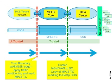
Classification and
marking of traffic flows creates a trust boundary within the network edges.
Within the trust
boundaries, received CoS or DSCP values are simply accepted and matched rather
than remarked. Classification and marking are applied at the network edge,
close to the traffic source, in Service Provider Cisco HCS Data Center design,
at the Nexus 1000V virtual access switch for traffic originating from Unified
Communications applications and at the MPLS WAN edge for traffic entering the
Service Provider Cisco HCS Data Center infrastructure. The trust boundary in
Service Provider Cisco HCS Data Center is at the Nexus 7000 Access/Aggregation
device connecting to the UCS (and Nexus 1000V), and on the Nexus 7000 DC Core
connecting to the MPLS WAN edge router as follows:
Figure 1. Trust
Boundaries and Policy Enforcement Points From Cisco HCS Customer to Service
Provider Data Center
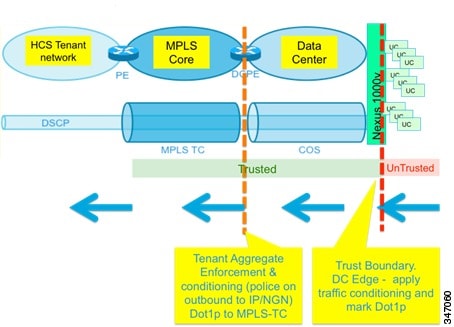
Figure 2. Trust
Boundaries and Policy Enforcement Points - Service Provider Data Center to
Cisco HCS Customer Site
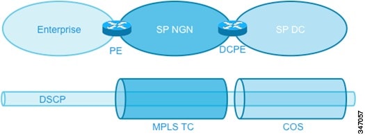
Quality of Service
Domains
There are three
distinct diffserv QoS domains:
SP data center
SP NGN
HCS customer
site
Traditionally,
network and bandwidth resource provisioning for VPN networks was implemented
based on the concept of specifying traffic demand for each node pair belonging
to the VPN and reserving resources for these point-to-point pipes between the
VPN endpoints. This is what has come to be termed the resource "pipe" model.
The more recently introduced "hose" model for point-to-cloud services defines a
point-to-multipoint resource provisioning model for VPN QoS, and is specified
in terms of ingress committed rate and egress committed rate with edge
conditioning. In this model, the focus is on the total amount of traffic that a
node receives from the network (that is, customer aggregate) and the total
amount of traffic it injects into the network.
Figure 3. Point to
Multipoint Resource Provisioning Model for VPN QoS
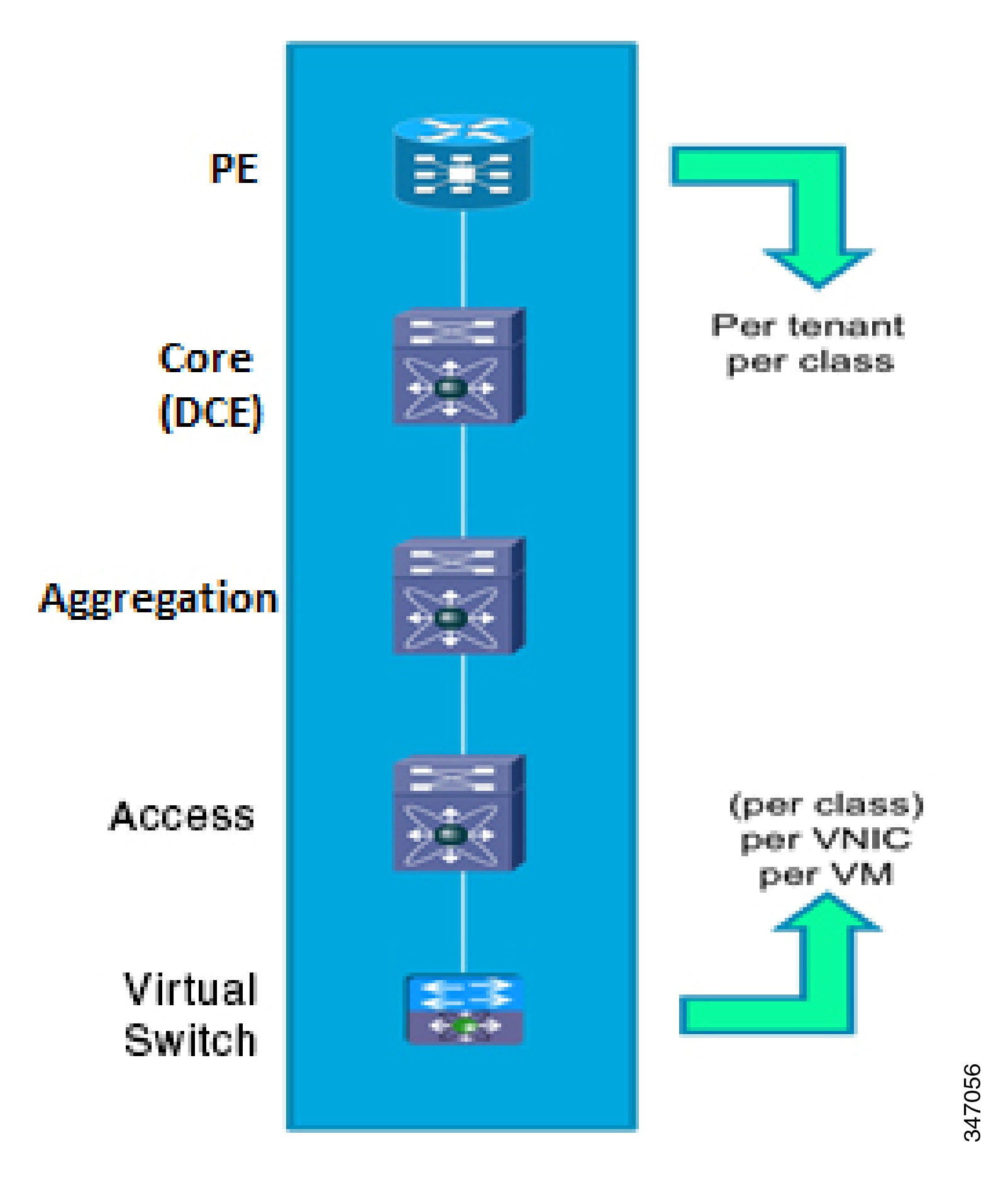
Any SLAs that are
applied would be committed across each domain; thus, SP end-end SLAs would be a
concatenation of domain SLAs (IP/NGN + SP DC). Within the VMDC SP DC QoS domain
SLAs must be committed from DC edge to edge: at the PE southbound (into the DC)
in practice there would thus be an SLA per-customer per class, aligning with
the IP/NGN SLA and at the N1000VV northbound there would be an SLA per VNIC per
VM (optionally per class per VNIC per VM). As this model requires per-customer
configuration at the DC edges only (that is, PE and N1000V), there is no
per-customer QoS requirement at the core/aggregation/access layers of the
infrastructure as shown below:
Figure 4. Per-Customer
QoS Configuration
Note
There is no
requirement to enable any QoS on the ASA.
Note
Inter-customer or
off-net traffic goes through SBC, which means all the signaling and media is
terminated and re-originated by the SBC. This step erases the QoS setting of
all the outgoing traffic. Make sure the SBC QoS policy is similar to what is
set by the applications or DC edge (Nexus 1000V) or else the policy may get
changed by SBC.
Cross-Platform
Classification and Marking
As previously
stated, the VMDC QoS model must support the requirements of Cisco HCS and it
will align with the IP NGN QoS model. To this end, suggested classifications
and markings, aligned across the SDU Systems Architectures and in particular
with the HCS model, are summarized in the following table. This provides a
unified framework facilitating future additions of various traffic types into
the VMDC architecture in addition to the Cisco HCS-specific traffic.
Table 4. Class to Queue
Mapping
VMDC 8 Class Model
COS
VMDC HCS Aligned 8 Class Model
VMDC NGN Aligned 8 Class Model
VMDC (Unified Communications System 6xx0) 6 Class Model
Cisco HCS 6 Class Model
4 Class Model Nexus 7000 Fabric
Network Mgmt + Service control
7
Network Mgmt + VM control
Network Mgmt + VM control
Network Mgmt (COS 7) + Service control (COS 7) + Network control
(COS 6)
Network Mgmt (COS 7) + Service control (COS 7) + Network control
(COS 6)
Queue 1
Network control
6
Network control
Network control
Priority #1
5
Voice bearer
Res VoIP / Bus Real-time
Priority #1
Voice bearer
Bandwidth #1 (Priority 2)
4
Interactive Video
Video streaming
Bandwidth #1
Interactive Video
Queue 2
Bandwidth #2
3
Call Control/FCOE
Video interactive / FCOE
FCOE (Bandwidth #2)
Call Control/FCOE
Bandwidth #3 "Gold"
2
Business Critical
Bus critical
in-contract (COS 2)
Bus critical
out-of-contract (COS 1)
Bus critical
in-contract (COS 2)
Bus critical
out-of-contract (COS 1)
Silver
In-contract (COS 2)
Out-of-contract (COS 1)
Business Critical
Queue 3
Bandwidth #4 "Silver"
1
Webex collaboration data (interactive)
Silver
In-contract (COS 2)
Out-of-contract (COS 1)
Webex collaboration data + Standard data
Queue 4
Standard (Bandwidth #5) "Bronze"
0
Standard data
Standard data
Standard
The number of classes
supported within the SP DC QoS domain is limited by the number of CoS markings
available (up to eight), and the number of queues/thresholds supported by each
DC platform. To ensure a seamless extension of NGN services, the number of
classes would ideally (at a minimum) match the number available across the
IP/NGN.
The following table
shows all the classes with PHB values, with admission requirements for some
classes, and maps to various applications.
Table 5. Application
Classes, Behavior and Examples
Application Class
Per-Hop Behavior
Admission Control
Queuing and Dropping
Application Examples
VoIP telephony
EF
Required
Priority Queue (PQ)
Cisco IP Phone (G.711, G.729)
Broadcast video
CS5
Required
PQ (optional)
Cisco IP Video Surveillance / Cisco Enterprise TV
Realtime interactive
CS4
Required
PQ (optional)
Cisco TelePresence
Multimedia conferencing
AF4
Required
BW Queue + DSCP WRED
Cisco Unified Personal Communicator, WebEx
Multimedia streaming
AF3
Recommended
BW Queue + DSCP WRED
Cisco Digital Media System (VoDs)
Network control
CS6
N/A
BW Queue
EIGRP, OSPF, BGP, HSRP, IKE
Call signaling
CS3
N/A
BW Queue
SCCP, SIP, H.323
OAM
CS2
N/A
BW Queue
SNMP, SSH, Syslog
Transactional data
AF2
N/A
BW Queue + DSCP WRED
ERP Apps, CRM Apps, Database Apps
Bulk data
AF1
N/A
BW Queue + DSCP WRED
Email, FTP, Backup Apps, Content Distribution
Best effort
DF
N/A
Default Queue + RED
Default Class
Scavenger
CS1
N/A
Min BW Queue (Deferential)
YouTube, iTunes, BitTorent, Xbox Live
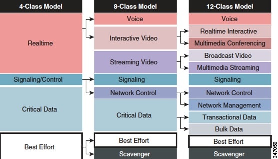
In general, four
classes (sometimes read as five classes due to the fact the signaling and
control may be defined differently) is the recommended model for provisioning
QoS for Voice, Video and Data. Some of these classes can be gradually split
into more granular classes, as shown in the following figure. Classification
recommendations remain the same, but you can combine multiple DSCPs into a
single queuing class.
The
Real-Time
queue is for voice and video traffic in general, as they are time-sensitive
applications.
Signaling/control
includes all the control signaling, meaning call signaling, and also includes
the management control traffic including the vMotion traffic.
Critical data
includes any bulk data transfer, which may include databases, and
so on.
The last
best effort
class includes anything other than the traffic described in the preceding
text, for example, Internet traffic.
Figure 5. QoS Class
Models
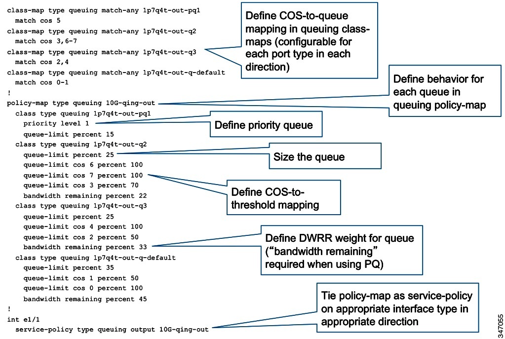
An example of
queuing policy on the Nexus 7000 in the HCS data center is as follows:
Figure 6. Example
Queuing Policy
The Cisco NX-OS
device processes the QoS policies that you define based on whether they are
applied to ingress or egress packets. The system performs actions for QoS
policies only if you define them under the type
qos service
policies.
The recommended
Cisco HCS QoS model appears in the following table.
Table 6. Cisco HCS QoS
Model
HCS Traffic
EXP/COS
DSCP
PHB
BW Res (N5000, ASA, N7000-Ingress)
Nexus 1000
Unified Communications System
Nexus 7000-Egress
ASR9000
Network Mgmt
7
CS7
AF
6%(vmdc) WRED
6%
Default in Unified Communications System
1p7q4t-out-q7
Network Control + vMotion +VM Control
6
CS6
AF
4%(vmdc) WRE
10%
Platinum (10%)
1p7q4t-out-q6
Voice Bearer
5
CS5
EF
15%(vmdc) no drop
15% (cir=50mbpc=200 per VM)
Gold (15%)
1p7q4t-out-q5
cir=50 per VM, 100 per cust
Interactive Video (WebEx, SPT)
4
CS4
AF41
15% no drop
15% (cir=50 ms, bc=200 per VM)
Silver(15%)
1p7q4t-out-q4
Call Control +FCoE
3
CS3
AF42, AF43
3%(vmdc)
N/A
FC(40%)
1p7q4t-out-q3
WebEx Data, other critical data
1,2
CS1, CS2
AF
42%
44%
Bronze(10%)
1p7q4t-out-q2
250 mbps per VM 500 mbps per cust/3G burst
Standard
0
CS0
Default
15%(vmdc)
10%
Best Effort (10%)
1p7q4t-out-q-default
As shown in the
preceding table, Cisco HCS uses the CoS-based marking within the data center
and mapping of CoS to DSCP. You can use a similar approach in the UCS combined
with enabling the flow control between the UCS network port and the uplink port
to protect the drop of data in the case of congestion at the UCS uplink. You
can achieve this by using the DCE pause frame technique, which sends pause
frames to the uplink port to hold the traffic for a few milliseconds while the
congestion at the UCS level is cleared.
Normally in Cisco
HCS, the traffic that flows through the UCS is only Cisco HCS application
traffic, which is mostly the signaling traffic (meaning that it requires not
that much of the bandwidth). Also because we are using 10GE links between all
the uplink and network ports, for Cisco HCS one should have enough bandwidth
and may not need to enable the pause frame flow control technique.
Note
You can apply only
ingress traffic actions for QoS policies on Layer 2 interfaces. You can apply
both ingress and egress traffic actions on Layer 3 interfaces.
Quality of Service
for Audio and Video Media from Softphones
An integral part of the Cisco Unified Communications network design
recommendations is to classify or mark voice and video traffic so that it can
be prioritized and appropriately queued as it traverses the Unified
Communications network. A number of options exist to set the DSCP values of
audio and video traffic generated by clients. For example:
Using a Unified CM Trusted
Relay Point to enforce DSCP marking for QOS on behalf of a softphone client
registered with Unified CM.
Using network-based access
control lists (ACLs) to mark DSCP values for voice and video traffic.
Using Active Directory Group
Policy to mark DSCP values for voice and video traffic. Note that many
operating systems limit the ability of applications to mark traffic with DSCP
values for QoS treatment.
QOS Enforcement
Using a Trusted Relay Point (TRP)
A Trusted Relay Point (TRP) can be used in conjunction with the device
mobility feature to enforce and/or re-mark the DSCP values of media flows from
endpoints. This feature allows QoS to be enforced for media from endpoints such
as softphones, where the media QoS values might have been modified locally.
A TRP is a media resource based upon the existing Cisco IOS media
termination point (MTP) function. Endpoints can be configured to
Use Trusted Relay Point, which will invoke a TRP
for all calls.
For QoS enforcement, the TRP uses the configured QoS values for media in
Unified CM's Service Parameters to re-mark and enforce the QoS values in media
streams from the endpoint. If no TRP is available, the call will proceed
without modification of the DSCP value of the traffic generated by the
endpoint. Cisco IOS MTPs and transcoding resources support TRP functionality.
(Use Unified CM to check
Enable TRP on the MTP or transcoding resource to
activate TRP functionality.)
Client Services
Framework – Instant Messaging and Presence Services
Instant messaging and presence services for Jabber clients can be provided through the Cisco Client Services Framework XMPP
interface. Cisco offers instant messaging and presence services with the following products:
The choice between Cisco IM and Presence or Cisco Webex Messenger for instant messaging and presence services can depend on a number of factors. Cisco Webex Messenger deployments use Cisco Webex as a cloud-based service that is accessible from the Internet. On-premises deployments based on Cisco IM and Presence provide
the administrator with direct control over their IM and presence platform and also allow presence federation using SIP/SIMPLE
to Microsoft IM and presence services.
For information on the full set of features supported by each IM and Presence platform, refer to the following documentation:
Cisco IM and Presence
Cisco Webex Messenger
Note
With Cisco UC Integration for Microsoft Lync, Microsoft provides instant messaging and presence services.
Client Services
Framework – Audio, Video and Web Conferencing Services
Access to scheduled
conferencing services for clients can be provided through a Cisco Client
Services Framework HTTP interface.
Cisco audio, video and web-based scheduled conferencing services can be provided by using the cloud-based Cisco Webex Meetings service or a combination of on-premises MeetingPlace audio and video conferencing services and WebEx cloud-based web conferencing
services. For more information, refer to the Cisco Webex Meetings documentation at http://www.cisco.com/c/en/us/support/conferencing/webex-meeting-center/tsd-products-support-series-home.html.
Client Services
Framework – Contact Management
The Client Services Framework can handle the management of contacts through a number of sources, including the following:
Cisco Unified CM User database via the User Data Service (UDS)
LDAP directory integration
Cisco Webex Messenger
Contacts can also be stored and retrieved locally using either of the following:
Client Services Framework Cache
Local address books and contact lists
The Client Services Framework uses reverse number lookup to map an incoming telephone number to a contact, in addition to
photo retrieval. The Client Services Framework contact management allows for up to five search bases to be defined for LDAP
queries.

 Feedback