QSIG/DPNSS Phone System with Cisco EGW 2200 Integration Guide for Cisco Unity Connection 10.x
Available Languages
Table of Contents
Task List to Create the Integration
Integrations with Multiple Phone Systems
Planning How the Voice Messaging Ports Will Be Used by Cisco Unity Connection
The Number of Voice Messaging Ports to Install
The Number of Voice Messaging Ports That Will Answer Calls
The Number of Voice Messaging Ports That Will Dial Out
Considerations for a Cisco Unity Connection Cluster
When Both Cisco Unity Connection Servers Are Functioning Normally
When Only One Cisco Unity Connection Server Is Functioning
Programming the QSIG/DPNSS Phone System
Creating a New Integration with the QSIG/DPNSS Phone System
Adding New User Templates for Multiple Integrations
Appendix: Documentation and Technical Assistance
Cisco Unity Connection Documentation
Obtaining Documentation and Submitting a Service Request
Cisco Product Security Overview
QSIG/DPNSS Phone System with Cisco EGW 2200 Integration Guide for Cisco Unity Connection Release 10.x
This document provides instructions for integrating a QSIG/DPNSS phone system with Cisco Unity Connection through a Cisco EGW 2200.
Integration Tasks
Before doing the following tasks to integrate Cisco Unity Connection with a QSIG/DPNSS phone system through a Cisco EGW 2200, confirm that Cisco Unity Connection is ready for the integration by completing the applicable tasks in the Installation Guide for Cisco Unity Connection.
The following task list describes the process for creating the integration.
Task List to Create the Integration
Use the following task list to integrate Cisco Unity Connection with the QSIG/DPNSS phone system.
1.
Review the system and equipment requirements to confirm that all phone system and Cisco Unity Connection server requirements have been met. See the “Requirements” section.
2.
3.
4.
5.
6.
7.
Requirements
The QSIG/DPNSS integration supports configurations of the following components:
- A QSIG/DPNSS phone system.
- The phone system ready for the integration as described in the documentation for the phone system and for the Cisco EGW 2200.
- A VoIP gateway configured and connected to the QSIG/DPNSS phone system.
- Cisco Unity Connection installed and ready for the integration, as described in the Installation Guide for Cisco Unity Connection at http://www.cisco.com/en/US/products/ps6509/prod_installation_guides_list.html.
- A license that enables the applicable number of voice messaging ports.
- A Cisco EGW 2200 ready for the integration as described in the Cisco EGW 2200 documentation.
- The Cisco EGW 2200 connected to the LAN and configured for a QSIG/DPNSS backhaul signaling stream from the VoIP gateway.
Cisco Unity Connection supports centralized voice messaging through the phone system, which supports various inter-phone system networking protocols including proprietary protocols such as Avaya DCS, Nortel MCDN, or Siemens CorNet, and standards-based protocols such as QSIG or DPNSS. Note that centralized voice messaging is a function of the phone system and its inter-phone system networking, not voicemail. Unity Connection will support centralized voice messaging as long as the phone system and its inter-phone system networking are properly configured. For details, see the “Centralized Voice Messaging” section in the “Integrating Cisco Unity Connection with the Phone System” chapter of the Design Guide for Cisco Unity Connection Release 10.x at http://www.cisco.com/en/US/docs/voice_ip_comm/connection/10x/design/guide/10xcucdgx.html.
Integration Description
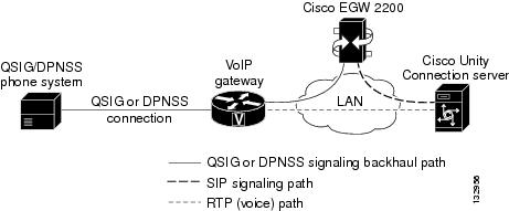
The QSIG/DPNSS integration uses a Cisco EGW 2200, which translates QSIG or DPNSS call signaling into SIP, a VoIP gateway, and the LAN to connect Cisco Unity Connection and a QSIG/DPNSS phone system. Figure 1 shows the required connections.
Figure 1 Connections Between a QSIG/DPNSS Phone System and Cisco Unity Connection
Call Information
The QSIG/DPNSS integration sends the following information with forwarded calls:
- The extension of the called party
- The extension of the calling party (for internal calls) or the phone number of the calling party (if it is an external call and the system uses caller ID)
- The reason for the forward (the extension is busy, does not answer, or is set to forward all calls)
Cisco Unity Connection uses this information to answer the call appropriately. For example, a call forwarded to Cisco Unity Connection is answered with the personal greeting of the user. If the phone system routes the call to Cisco Unity Connection without this information, Cisco Unity Connection answers with the opening greeting.
Integration Functionality
The QSIG/DPNSS integration with Cisco Unity Connection provides the following features:
- Call forward to personal greeting
- Call forward to busy greeting
- Caller ID
- Easy message access (a user can retrieve messages without entering an ID; Cisco Unity Connection identifies a user based on the extension from which the call originated; a password may be required)
- Identified user messaging (Cisco Unity Connection automatically identifies a user who leaves a message during a forwarded internal call, based on the extension from which the call originated)
- Message waiting indication (MWI)
Integrations with Multiple Phone Systems
When Cisco Unity Connection is installed as Cisco Business Edition—on the same server with Cisco Unified Communications Manager—Cisco Unity Connection cannot be integrated with multiple phone systems at one time.
When Cisco Unity Connection is not installed as Cisco Business Edition, Cisco Unity Connection can be integrated with two or more phone systems at one time. For information on and instructions for integrating Cisco Unity Connection with multiple phone systems, see the Multiple Phone System Integration Guide for Cisco Unity Connection Release 10.x at http://www.cisco.com/en/US/products/ps6509/products_installation_and_configuration_guides_list.html.
Planning How the Voice Messaging Ports Will Be Used by Cisco Unity Connection
Before programming the phone system, you need to plan how the voice messaging ports will be used by Cisco Unity Connection. The following considerations will affect the programming for the phone system (for example, setting up the hunt group or call forwarding for the voice messaging ports):
For a Cisco Unity Connection cluster, each Cisco Unity Connection server must have enough ports to handle all voice messaging traffic in case the other server stops functioning.
- The number of voice messaging ports that will answer calls.
- The number of voice messaging ports that will only dial out, for example, to send message notification, to set message waiting indicators (MWIs), and to make telephone record and playback (TRAP) connections.
The following table describes the voice messaging port settings in Cisco Unity Connection that can be set on Telephony Integrations > Port of Cisco Unity Connection Administration.
The Number of Voice Messaging Ports to Install
The number of voice messaging ports to install depends on numerous factors, including:
- The number of calls Cisco Unity Connection will answer when call traffic is at its peak.
- The expected length of each message that callers will record and that users will listen to.
- The number of users.
- The number of calls made for message notification.
- The number of MWIs that will be activated when call traffic is at its peak.
- The number of TRAP connections needed when call traffic is at its peak. (TRAP connections are used by Cisco Unity Connection web applications to play back and record over the phone.)
- The number of calls that will use the automated attendant and call handlers when call traffic is at its peak.
- Whether a Cisco Unity Connection cluster is configured. For considerations, see the “Considerations for a Cisco Unity Connection Cluster” section.
It is best to install only the number of voice messaging ports that are needed so that system resources are not allocated to unused ports.
The Number of Voice Messaging Ports That Will Answer Calls
The calls that the voice messaging ports answer can be incoming calls from unidentified callers or from users. Assign all of the voice messaging ports to answer calls.
You can set voice messaging ports to both answer calls and to dial out (for example, to send message notifications).
If your system is configured for a Cisco Unity Connection cluster, see the “Considerations for a Cisco Unity Connection Cluster” section.
The Number of Voice Messaging Ports That Will Dial Out
Ports that will dial out can do one or more of the following:
- Notify users by phone, pager, or email of messages that have arrived.
- Turn MWIs on and off for user extensions.
- Make a TRAP connection so that users can use the phone as a recording and playback device in Cisco Unity Connection web applications.
If your system is configured for a Cisco Unity Connection cluster, see the “Considerations for a Cisco Unity Connection Cluster” section.
Considerations for a Cisco Unity Connection Cluster
If your system is configured for a Cisco Unity Connection cluster, consider how the voice messaging ports will be used in different scenarios.
When Both Cisco Unity Connection Servers Are Functioning Normally
- A hunt group is configured on the phone system to distribute calls equally to both Cisco Unity Connection servers.
- The network is configured to send incoming calls first to the subscriber server, then to the publisher server if no answering ports are available on the subscriber server.
- Both Cisco Unity Connection servers are active and handle voice messaging traffic for the system.
- In Cisco Unity Connection Administration, the voice messaging ports are configured so that an equal number of voice messaging ports are assigned to each Cisco Unity Connection server. This guide directs you to assign the voice messaging ports to their specific server at the applicable time.
- The number of voice messaging ports that are assigned to one Cisco Unity Connection server must be sufficient to handle all of the voice messaging traffic for the system (answering calls and dialing out) when the other Cisco Unity Connection server stops functioning.
If both Cisco Unity Connection servers must be functioning to handle the voice messaging traffic, the system will not have sufficient capacity when one of the servers stops functioning.
If all the voice messaging ports are assigned to one Cisco Unity Connection server, the other Cisco Unity Connection server will not be able to answer calls or to dial out.
When Only One Cisco Unity Connection Server Is Functioning
- The hunt group on the phone system sends all calls to the functioning Cisco Unity Connection server.
- The functioning Cisco Unity Connection server receives all voice messaging traffic for the system.
- The number of voice messaging ports that are assigned to the functioning Cisco Unity Connection server must be sufficient to handle all of the voice messaging traffic for the system (answering calls and dialing out).
- The functioning Cisco Unity Connection server must have voice messaging ports that will answer calls and that can dial out (for example, to set MWIs).
If the functioning Cisco Unity Connection server does not have voice messaging ports for answering calls, the system will not be able to answer incoming calls. Similarly, if the functioning Cisco Unity Connection server does not have voice messaging ports for dialing out, the system will not be able to dial out (for example, to set MWIs).
Programming the QSIG/DPNSS Phone System
For information on provisioning a QSIG or DPNSS phone system to integrate with Cisco Unity Connection, see the Cisco EGW 2200 documentation.

Setting Up the Cisco EGW 2200
For information on setting up the Cisco EGW 2200, see the Cisco EGW 2200 documentation.

Note
Creating a New Integration with the QSIG/DPNSS Phone System
After ensuring that QSIG/DPNSS phone system and Cisco Unity Connection are ready for the integration, do the following procedure to set up the integration and to enter the port settings.
Step 1
Step 2
Step 3
Step 4
Step 5
Step 7
Step 8
Select the name of the phone system that you entered in Step 4.
Select Port Group Template and select SIP in the drop-down box.
Enter a descriptive name for the port group. You can accept the default name or enter the name that you want.
Enter the voice messaging pilot number that matches the dial plan configuration of the gateway.
Select the SIP transport protocol that Cisco Unity Connection will use.
Enter the IP address (or host name) of the primary gateway that you are connecting to Cisco Unity Connection.
Do not enter a value in this field. IPv6 is not supported for EGW 2200 integrations.
Enter the IP address (or host name) of the primary gateway that you are connecting to Cisco Unity Connection.
Enter the IP port of the primary gateway that you are connecting to Cisco Unity Connection. We recommend that you use the default setting.
Step 9
a.
b.
c.
d.
e.
Step 10
Step 11
Enter the number of voice messaging ports that you want to create in this port group.
Note For a Cisco Unity Connection cluster, you must enter the total number of voice messaging ports that will be used by all Cisco Unity Connection servers. Each port will later be assigned to a specific Cisco Unity Connection server.
Select the name of the phone system that you entered in Step 4.
Select the name of the port group that you added in Step 8.
Step 12
Note
Step 13
Step 16
Step 17
Step 18
Step 19
Step 20
Step 21
If the test is not successful, the Task Execution Results displays one or more messages with troubleshooting steps. After correcting the problems, test the Unity Connection again.
Step 22
Testing the Integration
To test whether Cisco Unity Connection and the phone system are integrated correctly, do the following procedures in the order listed.
If any of the steps indicate a failure, see the following documentation as applicable:
- The installation guide for the phone system.
- Troubleshooting Guide for Cisco Unity Connection Release 10.x, available at http://www.cisco.com/en/US/docs/voice_ip_comm/connection/10x/troubleshooting/guide/10xcuctsgx.html.
- The setup information earlier in this guide.
To Set Up the Test Configuration
Step 1
Step 2
Caution The phone system must forward calls to the Cisco Unity Connection pilot number in no fewer than four rings. Otherwise, the test may fail.
Step 3
Step 4
Step 5
Step 6
Step 8
Step 9
Step 10
Step 12
Step 13
Step 14
Step 15
Step 17
Do not close the Cisco Unity Connection Administration window because you will use it again in a later procedure.
Step 18
Step 19
Step 20
To Test an External Call with Release Transfer
Step 1
Step 2
Step 3
Step 4
Step 5
Step 6
Step 7
Step 8
Step 9
Step 10
Step 1
Step 2
Step 3
Step 5
Step 6
Step 8
To Set Up Supervised Transfer on Cisco Unity Connection
Step 1
Step 2
Step 4
Do not close the Cisco Unity Connection Administration window because you will use it again in a later procedure.
Step 1
Step 2
Step 3
Step 4
Step 5
Step 6
Step 7
Step 8
Adding New User Templates for Multiple Integrations
When you create the first phone system integration, this phone system is automatically selected in the default user template. The users that you add after creating this phone system integration will be assigned to this phone system by default.
However, for each additional phone system integration that you create, you must add the applicable new user templates that will assign users to the new phone system. You must add the new templates before you add new users who will be assigned to the new phone system.
For details on adding new user templates, or on selecting a user template when adding a new user, see the “User Attributes” chapter of the System Administration Guide for Cisco Unity Connection Release 10.x. The guide is available at
http://www.cisco.com/c/en/us/td/docs/voice_ip_comm/connection/10x/administration/guide/10xcucsagx.html.
Documentation Conventions
The QSIG/DPNSS Phone System with Cisco EGW 2200 Integration Guide for Cisco Unity Connection Release 10.x uses the following conventions.
The QSIG/DPNSS Phone System with Cisco EGW 2200 Integration Guide for Cisco Unity Connection Release 10.x also uses the following conventions:
Note
Cisco Unity Connection Documentation
For descriptions and URLs of Cisco Unity Connection documentation on Cisco.com, see the Documentation Guide for Cisco Unity Connection. The document is shipped with Cisco Unity Connection and is available at http://www.cisco.com/en/US/products/ps6509/products_documentation_roadmaps_list.html.
Obtaining Documentation and Submitting a Service Request
For information on obtaining documentation, submitting a service request, and gathering additional information, see the monthly What’s New in Cisco Product Documentation, which also lists all new and revised Cisco technical documentation, at:
http://www.cisco.com/en/US/docs/general/whatsnew/whatsnew.html
Subscribe to the What’s New in Cisco Product Documentation as a Really Simple Syndication (RSS) feed and set content to be delivered directly to your desktop using a reader application. The RSS feeds are a free service and Cisco currently supports RSS Version 2.0.
Cisco Product Security Overview
This product contains cryptographic features and is subject to United States and local country laws governing import, export, transfer and use. Delivery of Cisco cryptographic products does not imply third-party authority to import, export, distribute or use encryption. Importers, exporters, distributors and users are responsible for compliance with U.S. and local country laws. By using this product you agree to comply with applicable laws and regulations. If you are unable to comply with U.S. and local laws, return this product immediately.
Further information regarding U.S. export regulations can be found at http://www.access.gpo.gov/bis/ear/ear_data.html.
Cisco and the Cisco Logo are trademarks of Cisco Systems, Inc. and/or its affiliates in the U.S. and other countries. A listing of Cisco's trademarks can be found at www.cisco.com/go/trademarks. Third party trademarks mentioned are the property of their respective owners. The use of the word partner does not imply a partnership relationship between Cisco and any other company. (1005R)
Any Internet Protocol (IP) addresses used in this document are not intended to be actual addresses. Any examples, command display output, and figures included in the document are shown for illustrative purposes only. Any use of actual IP addresses in illustrative content is unintentional and coincidental.
 Feedback